Engineering
Vol. 3 No. 6 (2011) , Article ID: 5699 , 4 pages DOI:10.4236/eng.2011.36068
Optimization of Permanent Magnet Skew in Permanent Magnet Linear Synchronous Motors Using Finite Element and Statistical Method
1Department of Electric Engineering, Universidad Carlos III de Madrid, Madrid, Spain
2Department of Mechanical Engineering, Universidad Carlos III de Madrid, Madrid, Spain
E-mail: ggonzalezp@uao.edu.co, {jrivas, elaniado}@ing.uc3m.es
Received December 31, 2010; revised May 10, 2011; accepted May 20, 2011
Keywords: FEM-Statistical regression method, optimization, PM skew, PMLSM, ripple, thrust
ABSTRACT
The permanent magnet skew is one of the techniques mostly used on the Permanent Magnet Linear Synchronous Motors (PMLSMs) to reduce the thrust ripple; even though there is a reduction in the amplitude of ripple and at the same time a significantly decrease of the motor’s thrust. This article proposes a combined technique between the Finite Elements Method (FEM) and statistical regression, to obtain an objective function that will allow the achievement of the optimal Permanent Magnet (PM) skew angle, so that there is a greater reduction of ripple with the minimum thrust diminishment.
1. Introduction
The PMLSMs are widely used for their excellent characteristics such as high force density, fast dynamic response, low thermal losses, and simple structure. However, the thrust ripple, which is the main disadvantage of PMLSM, results in a periodic force oscillation. Consequently, the periodic force oscillation causes mechanical vibration, acoustic noise, and speed oscillation, which will deterio-rate the performance of PMLSMs [1].
It is then necessary to look for a way of reducing the thrust’s ripple. To achieve the latter, a diversity of techniques are used and one of them is the skew of PM [1,2]. However, the skew also provokes a reduction in the thrust [3,4]; for which it will be necessary to implement a method to obtain the optimum skew angle so that there is a reduction in ripple without diminishing too much the motor’s thrust.
The existing Literature [5-14], considers diverse methods of optimization, but none establishes as objectives the maximization of thrust and the minimization of ripple. In addition, techniques that suppose certain degree of complexity like the genetic algorithms are used [6,11]. It is for that reason that this work considers a simpler technique that consists of using the data of thrust and ripple of the simulation by FEM, to obtain by means of quadratic regression the equations that follow the tendency of the data.
The equations are of second order, one for thrust (T) and another one for ripple (R), they are then combined to obtain an only objective function that is maximized and of which the optimal PMs skew is obtained.
The procedure is applied to two types of PMLSMs, the first one has a short pitch winding (PMLSM-1) and the second one has diametrical pitch winding (PMLSM-2). Figures 1 and 2, shows the structures of both motor.
Table 1 shows the most relevant dimensions of the two PMLSMs.
2. FEM Simulation
The simulations were made in a 3D FEM software for a displacement of the translator of a polar step and with 10 angles (θ) of skew of the PMs. The angles are measured in fractions of slot step (τs) and the chosen values of θ are: 1/4τs, 1/3τs, 1/2τs, 2/3τs, 3/4τs, 1τs, 5/4τs, 4/3τs y 3/2τs. For each PMLSM, ten simulations were made; consequently the total of simulations for each PMLSM was 20.
The thrust for each skew angle is a mean value of the data obtained for simulation, with a displace-ment of a polar step and rated current.
The thrust is expressed in P.U. values, taking as base
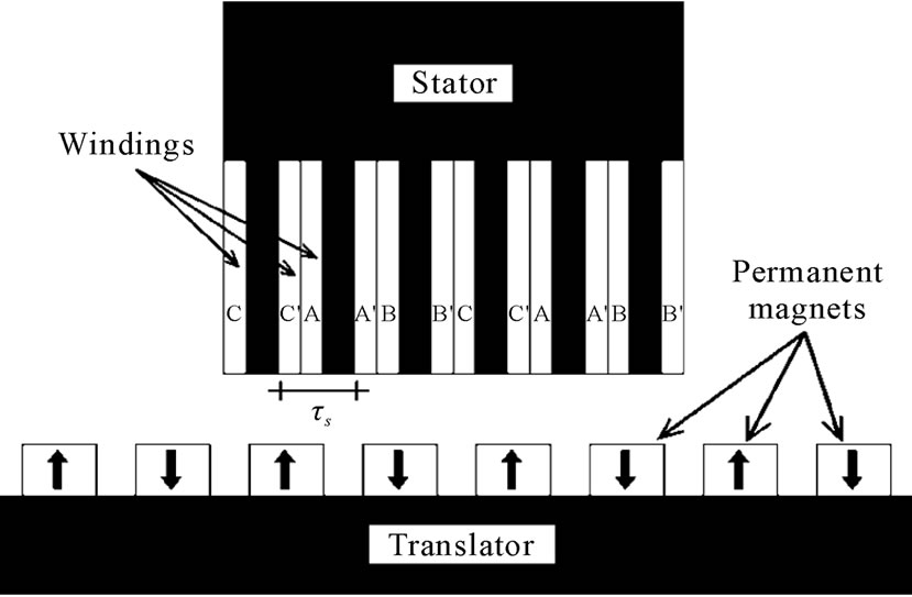
Figure 1. Structure of PMLSM-1.
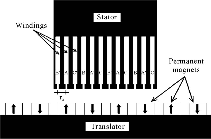
Figure 2. Structure of PMLSM-2.
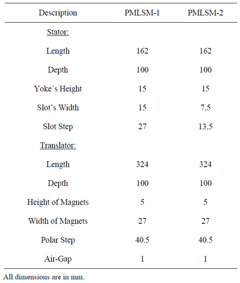
Table 1. Pmlsms dimensions.
value the thrust at θ = 0.
Ripple is analyzed taking as reference its amplitude; subtracting from the maximum value of thrust its minimum.
The relative permeability of iron is 2500, the relative permeability of the permanent magnets is 1.05, the current density is 8.33 A/mm2 and the speed of translator is 4.05 m/s.
The simulation was done in 51 steps of 0.2ms that correspond to displacements of 0.81 mm each and the meshing of the models has the following characteristics:
Number of nodes: 13736
Number of line elements: 3658
Number of surface elements: 21340
Number of volume elements: 76273
3. Data Processing
The resulting data of thrust and ripple obtained from the simulation by FEM is summarized in Table 2.
Quadratic regression by minimum squares is applied to the data of thrust and ripple using the function polyfit of Matlab, which gives the coefficients of an equation of second order that comes near to the data generated by the FEM.
The equations obtained for the PMLSM-1 are:
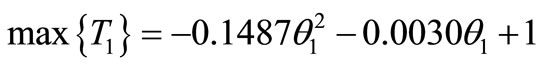 (1)
(1)
 (2)
(2)

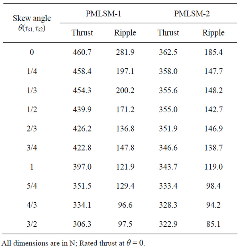
Table 2. Thrust and ripple data.
where:
T1: PMLSM-1 thrust in P.U.
R1: PMLSM-1 ripple in P.U.
θ: PM skew angle (τs1) in PMLSM-1.
As you can see, two functions exist to optimize and these are opposed.
Figure 3 shows the data of thrust and ripple in P.U. units, obtained by FEM and the curves of the equations obtained with the function polyfit of Matlab.
We can see the closeness of the data with the drawn up curve, with which the optimization can be validated later.
The same procedure is applied to PMLSM-2, which represents the thrust and ripple equations:
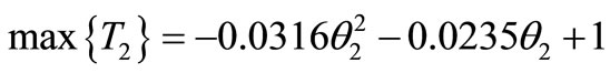 (3)
(3)
 (4)
(4)

Figure 4 shows data and curves obtained in P.U. units.
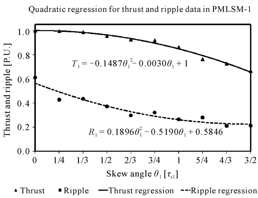
Figure 3. Thrust-Ripple data and equation in PMLSM-1.
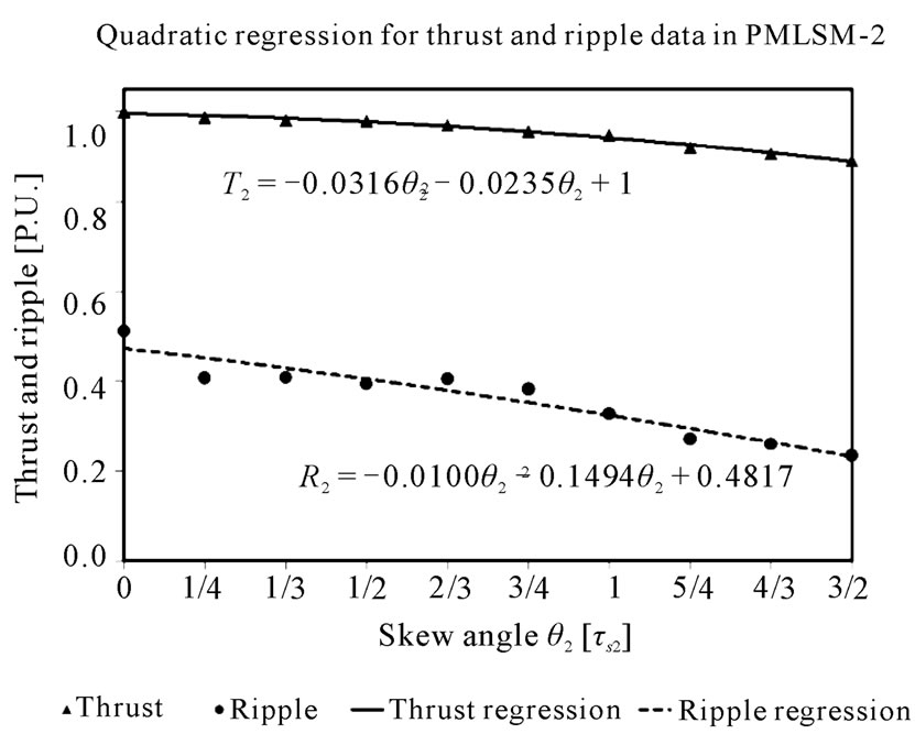
Figure 4. Thrust-Ripple data and equation in PMLSM-2.
4. Optimization
The established problem is of a multi objective optimization and to solve it the weighted-sum approach technique is applied [18], in order to find a unique objective function. This technique consists of giving a specific weight to each function and then they are added or subtracted. In (5) the general expression to apply is indicated.
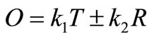 (5)
(5)
where O is the objective function to optimize and k1, k2 are the weights given to the functions of thrust (T) and ripple (R).
In the studied case, an equal weight of 1 is given to both functions [18], since maximization of ripple is as important as thrust diminishing.
 (6)
(6)
To obtain the unique objective function, the function of ripple is subtracted from the function of thrust. This operation can be made because the two functions are of 2nd order and they also have the same units. Then, the maximum of the resulting objective function is calculated and the optimum skew is obtained.
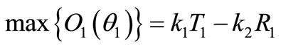
Next, the resulting objective function for PMLSM-1 is presented with its optimum skew.
 (7)
(7)

The optimal skew angle is.
 (8)
(8)
Figure 5 shows the objective function for PMLSM-1 that shows the optimum angle near 0.76 τS1.
The procedures are the same for PMLSM-2.
 (9)
(9)

The optimal skew angle is.
 (10)
(10)
Figure 6 shows the objective function for the PMLSM-2 that shows the optimum angle is 1.5 τS2.s On Table 3 we can see the values of thrust and ripple, evaluated by means of FEM with optimal skew.
These results indicate that a reduction of 50.9% of ripple in the PMLSM-1 is obtained, whereas thrust only diminishes 9.1%. In the PMLSM-2, ripple is reduced in 54.1% and thrust only diminishes 10.9%.
Figures 7 and 8 show the thrust without skew and optimal skew.
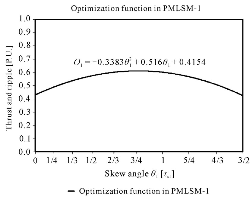
Figure 5. Objective function for PMLSM-1.
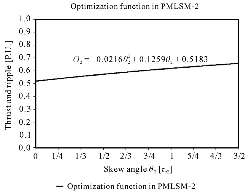
Figure 6. Objective function for PMLSM-2.
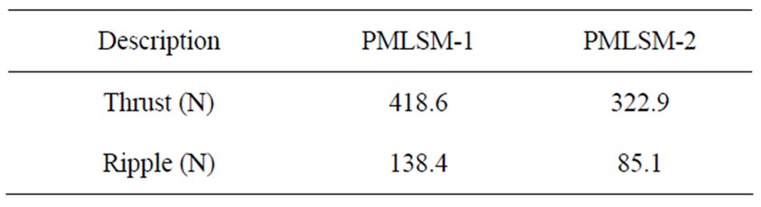
Table 3. PMLSM’s thrust and ripple by fem.
On the other hand, a common design objective is maximizing the thrust force while keeping the ripple force below a certain percentage of the thrust force, for that, is necessary change the k1 and k2 weights and introduce an additional condition [18].
 (11)
(11)
For example, to maintain the ripple force at 30% of thrust force in PMLSM-1, the restrictive condition is
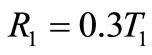 (12)
(12)
Consequently
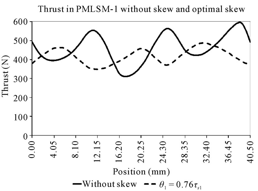
Figure 7. Thrust without skew and optimal skew for PMLSM-1.
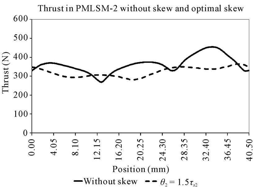
Figure 8. Thrust without skew and optimal skew for PMLSM-2.
 (13)
(13)
The objective function is
 (14)
(14)
 (15)
(15)

The optimal skew angle is.
 (16)
(16)
Computing in the optimal angle, the following results are obtained.
 (17)
(17)
 (18)
(18)
This indicates that the ripple value is 29.8% of the thrust. The difference with 30% is due to decimal taken into account.
Sometimes the priority is to reduce the ripple to the maximum, in other cases; the priority is to maximize the thrust, so it is necessary to give more weight to the role that is more important. To achieve this goal, we change the weights (k1, k2), so that, if the priority is to maximize the thrust, then k1 > k2, but if the priority is to minimize the ripple, then k1 < k2. Anyway, it is necessary to satisfy the condition (11).
5. Conclusions
The amplitude of ripple can be reduced significantly (50.9% in PMLSM-1 and 54.1% in the PMLSM-2) without diminishing thrust too much (9.1% in PMLSM-1 and 10.9% in PMLSM-2), using the combined method of FEMStatistical Regression to find optimal skew for the PM's. The advantage of the method is that it is very simple to apply and does not use very complex techniques.
The proposed method has the advantage of using a small number of finite element simulations, because they can perform to a certain number of skew angles and from these data are obtained, and trend curves from these curves are obtained optimal values. Otherwise, it would be necessary to run simulations with very short steps and therefore would have a lot of time consuming simulation.
The methodology can be used also in cases in which it is desirable to limit the ripple to a certain percentage of the thrust. Additionally, the use of weight factors (k1, k2), it is useful to find optimal values in different circumstances, as in the case that gives equal importance to the maximization of the thrust and the ripple minimization. Also, the technique can be used for cases in which giving more importance to one of the functions to maximize or minimize.
6. REFERENCES
- M.S. Islam, S. Mir and T. Sebastian., “Issues in Reducing the Cogging Torque of Mass-Produced Permanent-Magnet Brushless DC Motor,” IEEE Transactions on Industry Applications, vol. 40, no. 3, 2004, pp. 813-820. doi:10.1109/TIA.2004.827469
- M. Aydin, “Magnet Skew in Cogging Torque Minimization of Axial Gap Permanent Magnet Motors,” 18th International Conference on Electrical Machines (ICEM 2008), 2008, pp. 1-6.
- I.-S. Jung, J. Hur and D.-S. Hyun, “Performance Analysis of Skewed PM Linear Synchronous Motor According to various Design Parameters,” IEEE Transactions on Magnetics, vol. 37, no. 5, 2001, pp. 3653-3657.
- M. Dai, A. Keyhani and T. Sebastian, “Torque Ripple Analysis of a Permanent Magnet Brushless DC Motor using Finite Element Method,” IEEE International Conference on Electric Machines and Drives (IEMDC 2001), Cambridge, 17-20 June 2001, pp. 241-245.
- J. H. Choi, J. H. Kim, D. H. Kim and Y. S. Baek, “Design and Parametric Analysis of Axial Flux PM Motors with Minimized Cogging Torque,” IEEE Transactions on Magnetics, vol. 45, no. 6, 2009, pp. 2855-2858.
- R. Wrobel, “Design Considerations of a Direct Drive Brushless Machine with Concentrated Windings,” IEEE Transaction on Energy Conversion, vol. 23, no. 1, 2008, pp. 1-8. doi:10.1109/TEC.2007.905073
- Y.-W. Zhu, D.-H. Koo and Y.-H. Cho, “Detent Force Minimization of Permanent Magnet Linear Synchronous Motor by Means of Two Different Methods,” IEEE Transactions on Magnetics, vol. 44, no. 11, 2008, pp. 4345- 4348. doi:10.1109/TMAG.2008.2001320
- Y.-W. Zhu and Y.-H. Cho, “Thrust Ripples Suppression of Permanent Magnet Linear Synchronous Motor,” IEEE Transactions on Magnetics, vol. 43, no. 6, 2007, pp. 2537-2539. doi:10.1109/TMAG.2007.893308
- W. Z. Fei and J. X. Shen, “Comparative Study and Optimal Design of PM Switching Flux Motors,” Proceedings of the 41st International Conference on Universities Power Engineering (UPEC’06), Newcastle-Upon-Tyne, 6-8 September 2006, pp. 695-699.
- S. Huang, M. Aydin and T. A. Lipo, “Electromagnetic Vibration and Noise Assessment for Surface Mounted,” Power Engineering Society Summer Meeting, IEEE, Vancouver, vol. 3, 2001, pp. 1417-1426.
- M. Lukaniszyn, M. JagieLa and R. Wrobel, “Optimization of Permanent Magnet Shape for Minimum Cogging Torque Using a Genetic Algorithm,” IEEE Transactions on Magnetics, vol. 40, no. 2, 2004, pp. 1228-1231.
- S. R. Huang, M. Aydin and T. A. Lipo, “Torque Quality Assessment and Sizing Optimization for Surface Mounted Permanent Magnet Machines,” Industry Applications Conference, 2001, Thirty-Sixth IAS Annual Meeting, Conference Record of the 2001 IEEE, Chicago, 2001, pp. 1603-1610.
- M. Aydin, S. Huang and T. A. Lipo, “Optimum Design and 3D Finite Element Analysis of Nonslotted and Slotted Internal Rotor Type Axial Flux PM Disc Machines,” Power Engineering Society Summer Meeting, 2001, IEEE, vol. 3, 2001, pp. 1409-1416.
- M.S. Islam, “Design Considerations of Sinusoidally Excited Permanent-Magnet Machines for Low-Torque-Ripple Applications,” IEEE Transactions on Industry Applications, vol. 41, no. 4, 2005, pp. 955-962, doi:10.1109/TIA.2005.851026
- J. Lee, H.-W. Lee, Y.-D. Chun, M. Sunwoo and J.-P. Hong, “The Performance Prediction of Controlled-PM LSM in various Design Schemes by FEM,” IEEE Transactions on Magnetics, vol. 36, no. 4, 2000, pp. 1902- 1905,. doi:10.1109/20.877818
- G.G. Palomino and J. R. Conde, “Ripple Reduction in a PMLSM with Concentrated Winding Using 2-D Finite Element Simulation,” 4th IET Conference on Power Electronics, Machines and Drives (PEMD 2008), York, 2-4 April 2008, pp. 451-454.
- G. G. Palomino and J. R. Conde, “Comparative results of thrust ripple in several topologies of PMLSM,” 4th IET Conference on Power Electronics, Machines and Drives PEMD (2008), York, 2-4 April 2008, pp. 135-138.
- J. S. Arora, “Introduction to Optimum Design,” 2nd Edition, Elsevier Academic Press, Amsterdam, 2004, pp. 555-558.