Wireless Engineering and Technology
Vol.4 No.1(2013), Article ID:27644,6 pages DOI:10.4236/wet.2013.41003
Broadband Feed for Low Cross-Polarization Uniplanar Tapered Slot Antennas on Low-Permittivity Substrate
![]()
Department of Electrical and Computer Engineering, University of Victoria, Saanich, Canada.
Email: j.bornemann@ieee.org
Received November 20th, 2012; revised December 19th, 2012; accepted December 30th, 2012
Keywords: Tapered Slot Antenna; Ultra-Wideband; Microstrip; Slotline; Planar Transmission Lines
ABSTRACT
A broadband feeding technique for the uniplanar tapered slot antenna (TSA) is presented. The TSA operates at a center frequency of 6.5 GHz with a 7 GHz bandwidth (107 percent). The antenna and feed are realized with a broadband microstrip-to-slotline transition on a low permittivity high frequency substrate, Rogers RT/Duroid 5880. The input impedance of the system is designed for 50 Ω compatibility with other system components, and the cross polarization is kept below –30 dB. The developed TSA system was simulated with commercially available electromagnetic software and manufactured. Measured results validate the design process and the antenna’s performance.
1. Introduction
Omnidirectional ultra-wideband (UWB) antennas and related applications attracted increasing attention during the past decade for use in personal area network (PAN) communication applications, e.g. [1].
Directional UWB antennas are employed in radio astronomy receivers where TSA antennas are used to collect extra terrestrial radiation over a large bandwidth. For this purpose, a TSA system is usually mounted within an array setup, e.g. [2-5]. Mounting TSA systems in an array puts certain limits on the dimensions of the single TSA. Together with the need for non-complicated and inexpensive manufacturing processes, due to the huge amount of single TSAs elements needed, printed-circuit board (PCB) technology is found to accommodate the encountered restrictions very well.
TSA systems are well-examined and known antenna types [6,7]. Therefore, several papers and books on the different components of a TSA system are available and discuss related planar transmission lines (PTLs) [8] and transitions involving microstrip and slotlines [9-14].
It has been demonstrated that the antipodal TSA, with fins on opposite sides of the substrate, is easily fed by a microstrip line over a wide bandwidth [15-17]. However, it is the uniplanar TSA, with both fins on the same substrate side, which is usually employed in large array applications. So far, though, its feed has limited the exploitation of an ultra-wide bandwidth [2,4].
The uniplanar TSA with a microstrip-to-slotline transition as feed is shown in Figure 1. Traditionally, the transition is realized on high-permittivity substrate [8,9] due to the availability of better slotline models. However, a TSA performs best on low-permittivity substrate. On highpermittivity material, its performance is known to be poor unless parts of the substrate in the antenna are removed. This puts an extra effort on fabrication which has to be avoided when TSA arrays are involved [2,4]. Another feed that can be considered is a transition from coplanar waveguide (CPW) to slotline. However, such a transition requires air bridges [18] which again add to additional fabrication effort.
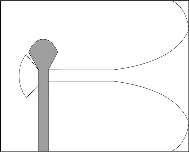
Figure 1. Circuit outline of broadband feed and uniplanar tapered slot antenna; microstrip line on top metallization, slotline with TSA on bottom metallization.
Therefore, several attempts have been made recently to integrate microstrip-to-slotline transitions on low-permittivity substrate [3,10,11,13]. While reasonable bandwidth has been obtained for the antenna system in [3], the application was limited to a one-dimensional array with no requirements for polarization purity. However, if uniplanar TSAs are used in two-dimensional arrays [2,4], then cross polarization presents a significant performance indicator. Other transitions either use a higher permittivity substrate [10,12,14] or are too narrowband [11,13] to accommodate a bandwidth in the order of 100 percent.
Therefore, this paper introduces an UWB feed for the uniplanar TSA on low-permittivity substrate that takes into consideration cross polarization as well as manufacturing limitations of a minimum slot width. The design is based on a modification of known structures but combines several aspects to obtain a UWB TSA system with a 7 GHz operational bandwidth at a center frequency of 6.5 GHz. Essential for this new design is the behavior of the electromagnetic field in the feed. It must be bound very tightly to the PCB and radiate well in the antenna part. This leads to critical design parameters such as characteristic impedance and substrate permittivity, which have to be chosen carefully.
The TSA system is examined theoretically, simulated with CST Microwave Studio, manufactured and measured. Good agreement between theory and experiment is obtained. This design is expected to significantly extend the bandwidth of TSA systems in polarization sensitive arrays for communications and radio astronomy applications.
2. Theoretical Considerations
To obtain a decision basis for the transmission-line components to be used in the TSA systems, several theoretical models for microstrip, slotline, coplanar waveguide (CPW) and coplanar stripline (CPS) have been calculated [8]. Only those satisfying constrains for UWB applications are considered here.
2.1. Planar Transmission Lines (PTLs)
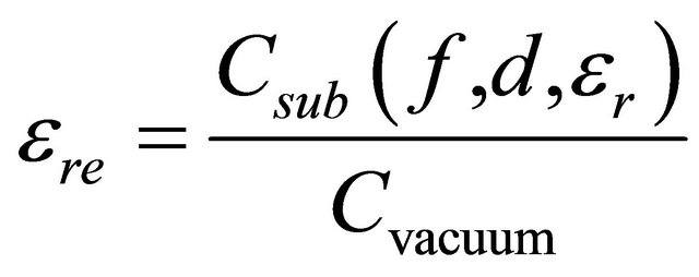
Critical for our purpose to develop an UWB feed with low cross polarization is the distribution, with respect to frequency, of the electromagnetic field in the system. Such properties are dominantly influenced by the physical setup of the differently charged conductors, leading to a general simplification for the frequency-dependent relative permittivity:
 (1)
(1)
where d is connected to the dimension of the specific PTL type,  the substrate’s relative permittivity, and Csub and Cvacuum the PTLs’ capacitance with substrate or vacuum, respectively, between the conductors.
The field distribution is also significantly influenced by the orientation of the fields that determines the amount of energy traveling within the substrate or in air.
The PTLs have been categorized as follows: microstrip and CPW are considered as primary PTLs, whereas secondary PTLs are slotline and CPS. This classification is based on the fact that the primary group can easily be designed to match a characteristic impedance of Zchar,in = 50 Ω on a wide variety of commonly used PCB substrates and that the secondary group is easily transformable to a TSA by simply widening the PTL.
Calculations of the primary PTLs [8] regarding the frequency-dependent relative permittivity show strong advantages for microstrip lines. Here, due to the physical conductor setup, the fields are propagating mainly within the substrate, which is advantageous in terms of dispersion and radiation loss. The low loss advantage is important to obtain the freedom to choose a substrate with an  as low as possible in order to support radiation from the TSA without removing the substrate between the antenna fins.
Theoretical calculations [8] for the secondary PTLs lead to the result that the slotline outperforms the CPS when aiming for low characteristic impedance Zchar. However, the characteristic impedance of the slotline is usually limited to a lower boundary by manufacturing restrictions as will be considered in Section 2.3.
Based on these results, microstrip as primary PTL and slotline as secondary PTL are used for the TSA system.
2.2. Tapered Slot Antennas (TSAs)
An overview over the different TSA types is presented in [7]. To obtain small dimension, as mentioned above, the TSA profile is selected as an exponential taper, as first introduced in [6], which offers the shortest taper for broadband purposes. The taper in Figure 1 is determined by
 (2)
(2)
where wTSA presents one half of the width between the fins, A adds an offset to the curve determined by the width of the secondary PTL (slotline with wsl = 150 m), and p = 0.125 characterizes the slope of the taper influenced by the overall length (1.5 at 6.5 GHz), the operational frequency range and the radiation characteristics of the TSA. Additionally, the sharp edges, which occur when the taper meets the radiating end of the substrate, are rounded to avoid disturbances and reflections in the electromagnetic fields (Figure 1). These features may later be replaced by corrugations [15] to limit the overall height of the antenna for array applications.
Moreover, it is found that the advantage of a lowpermittivity substrate on the radiation characteristics compensates for the loss along the PTLs.
2.3. Transitions
The microstrip-to-slotline transition presented in [9] matches the basic requirements for this application. However, it is presented in a back-to-back setup on a highpermittivity substrate. Therefore, the single transition is redesigned on a low-permittivity substrate for which Rogers RT/Duorid 5880 material with  = 2.2 and height hS = 787 μm is selected. Ideally, the basic constraint for this redesign is:
 (3)
(3)
The characteristic impedance of the microstrip line is designed to meet Zchar,ms = 50 Ω. However, due to manufacturing limitations, in which the smallest slot width cannot fall below 150 μm, the lowest reachable value for the characteristic impedance of the slotline is Zchar,sl = 81 Ω.
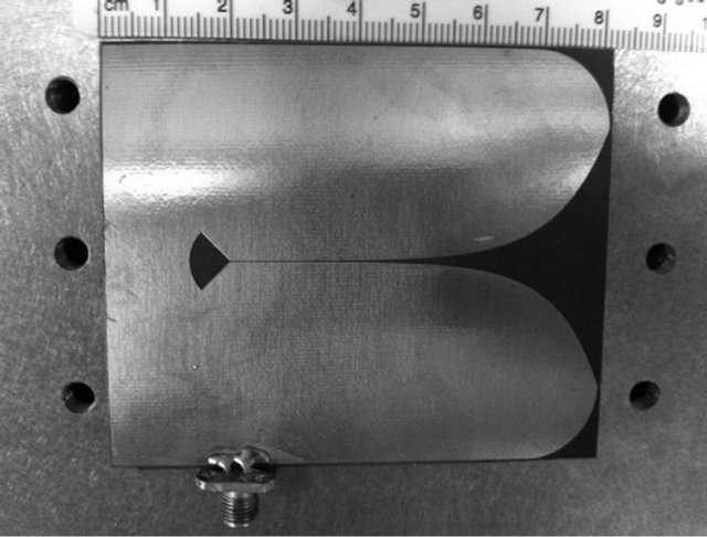
Figure 2(a) shows the top view of the TSA prototype which hosts the slot line components. The bottom view is depicted in Figure 2(b) and shows the microstrip circuitry. The two PTLs intersect at a 90˚ angle, and both lines are terminated with a 90˚ resonator whose length is  at midband frequency of 6.5 GHz. The fields are magnetically coupled, and the electric field rotates 90˚ in the transition.
 (a)
(a)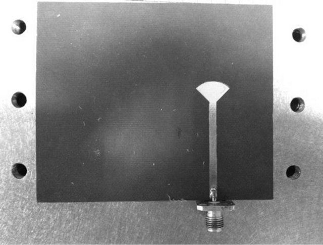 (b)
(b)
Figure 2. Photographs of the prototype TSA system: top view (a) With exponential taper and slotline with 90˚ stub resonator for termination; bottom view (b) With microstrip feed and 90˚ stub resonator.
3. Results
This section presents the performance of the UWB TSA system and compares simulated with measured results. All simulations are performed with CST Microwave Studio. Measurements use an Anritsu 37397C vector network analyzer (VNA).
Figure 3 presents a comparison of the reflection coefficient between the microstrip-to-slotline transition on high-permittivity substrate as proposed in [9] and the redesign on low-permittivity substrate used in this work. It is observed that our redesign is slightly better than the transition performance presented in [9] and that especially in the 4 GHz to 6.5 GHz range, the design used here is approximately 10 dB better than that in [9].
Figure 4 displays the effect of the rounded edges at the end of the taper by showing the input signal refection in the time domain. It is observed that the rounded edges are damping the reflected signal from 1.3 ns on and compressing the reflections between 0.7 ns and 0.5 ns.
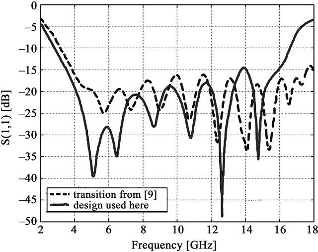
Figure 3. Single microstrip-to-slotline transition; redesign on low-permittivity substrate vs. transition introduced in [9] on high-permittivity substrate.
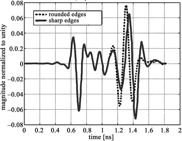
Figure 4. Time domain response of input signal taper with and without rounded edges.
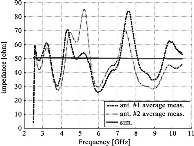
Figure 5 compares measurements and simulations with respect to input impedance. Note that two prototype antennas have been fabricated which are indicated as ant #1 and ant #2 in Figure 5. For the input impedance in Figure 5(a), the match between simulation and measurements is poor; even the two measured antennas do not agree. This is attributed to the influence of the SMA connectors and their difference in exact location and way of soldering.
 (a)
(a)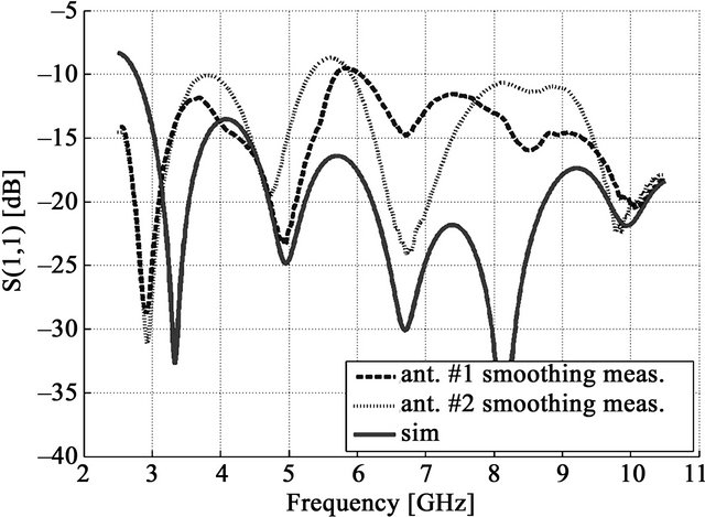 (b)
(b)
Figure 5. Comparison between measured and simulated results; (a) Input impedance; (b) Reflection coefficient in dB.
Radiation pattern measurements are performed in the anechoic chamber of the University of Victoria. The setup is presented in Figure 6 and uses Orbit/FR positioners and controllers, a quad-ridge horn by ETS Lindgren, an HP amplifier and the Anritsu VNA.
Full pattern measurements are performed at 4.5 GHz, 6.5 GHz and 8.5 GHz in coand cross-polarization with a 5˚ grid for 0˚ £ q £ 180˚ and 0˚ £ f £ 90˚. Note that the range of –90˚ £ f £ 0˚ was mirrored in the post processing process.
Figure 7 presents measurements for coand cross-polarization for the three measured frequencies. A suppression of more than 30 db in the direction of the main lobe is observed. This is an excellent result that is due to the uniplanar arrangement of the TSA. Typical antipodal TSAs display cross-polarization levels closer to 20 dB [15]. It is expected that the cross-polarization value of 30 dB in this work can be further improved by using corrugations in the metallic fins such as in [15-17].
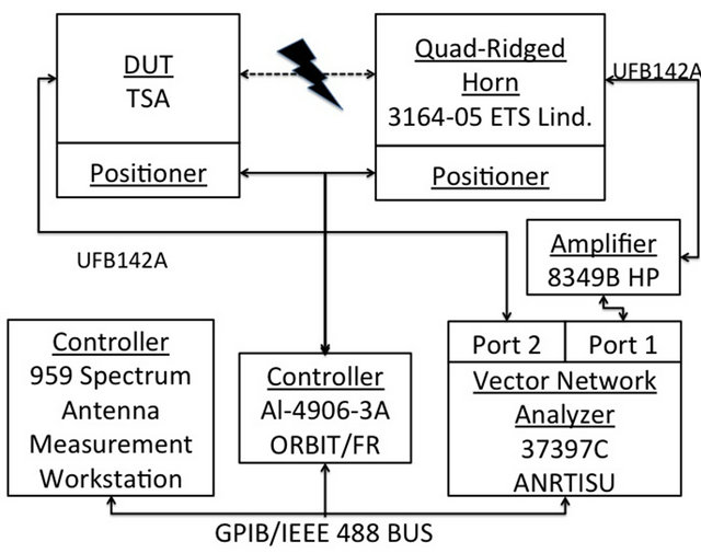
Figure 6. Setup for radiation pattern measurements.
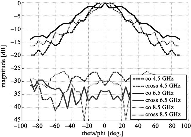
Figure 7. Measured coand cross-polarization at 4.5 GHz, 6.5 GHz and 8.5 GHz with data for negative angles mirrored from that of positive values.
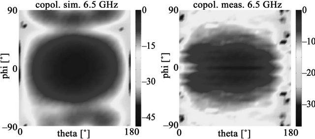
Figure 8 presents the simulated and measured radiation patterns for 6.5 GHz. A suitable agreement is observed, especially in the areas that matter for the cross polarization, namely the cardinal cuts, where the match is good. Moreover, the side lobes taper off even better in the measurements than in the simulations.
Unfortunately, calibrated gain measurements could not been carried out. Therefore, the simulated gain is shown in Figure 9 and shows an increase from 4 dB at 3 GHz to 8.4 dB at 10 GHz. Such a gain variation is quite common for UWB antennas.
 (a)
(a)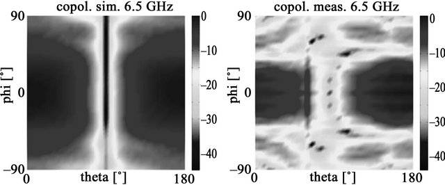 (b)
(b)
Figure 8. Beam pattern coand cross-polarization: Simulation (a, c), measurement (b, d).
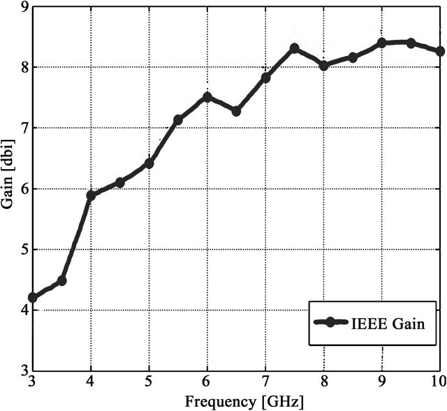
Figure 9. Simulated gain performance of unilateral TSA system.
4. Conclusion
A broadband feeding technique for the uniplanar TSA on low-permittivity substrate is presented. With a substrate permittivity of 2.2 it is possible to establish a good tradeoff between radiation characteristics and losses in the feed system. It is demonstrated that low loss, low input reflection coefficient and sufficiently suppressed crosspolarization characteristics are attainable over an ultrawide bandwidth in extent of 100 percent. Additionally, the TSA system shows sufficient gain values and directivity considering the wide 7 GHz bandwidth. Measurements on a prototype TSA system validate the design process, thus providing a solution for future UWB applications of the uniplanar tapered slot antenna in communications or radio astronomy applications.
5. Acknowledgements
The authors wish to acknowledge support for this work from the TELUS Research Grant in Wireless Communications.
REFERENCES
- Z. Irahhauten, J. Dacuña, G. J. M. Janssen and H. Nikookar, “UWB Channel Measurements and Results for Wireless Personal Area Networks Applications,” Proceedings European Conference on Wireless Technology, Paris, 3-4 October 2005, pp. 189-192.
- H. Holter, T.-H. Chio and D. H. Schaubert, “Experimental Results of 144-Element Dual-Polarized Endfire Tapered-Slot Phased Arrays,” IEEE Transactions on Antennas and Propagation, Vol. 48, No. 11, 2000, pp. 1707-1718. doi:10.1109/8.900228
- Y. Yao, M. Liu, W. Chen and Z. Feng, “Analysis and Design of Wideband Widescan Planar Tapered Slot Antenna Array,” IET Microwave, Antennas and Propagation, Vol. 4, No. 10, 2010, pp. 1632-1638. doi:10.1049/iet-map.2009.0226
- B. Veidt, G. J. Hovey, T. Burgess, R. J. Smegal, R. Messing, A. G. Willis, A. D. Gray and P. E. Dewdney, “Demonstration of a Dual-Polarized Phased-Array Feed,” IEEE Transactions on Antennas and Propagation, Vol. 59, No. 6, 2011, pp. 2047-2057. doi:10.1109/TAP.2011.2122231
- B. Y. El Khatib, T. Djerafi and K. Wu, “Three-Dimensional Architecture of Substrate Integrated Waveguide Feeder for Fermi Tapered Slot Antenna Array Applications,” IEEE Transactions on Antennas and Propagation, Vol. 60, No. 10, 2012, pp. 4610-4618. doi:10.1109/TAP.2012.2207323
- P. J. Gibson, “The Vivaldi Aerial,” 9th European Microwave Conference Proceedings, Brighton, 17-20 September 1979, pp. 101-105.
- K. S. Yngvesson, D. H. Schaubert, T. L. Korzeniowski, E. L. Kollberg, T. Thungren and J. F. Johansson, “Endfire Tapered Slot Antennas on Dielectric Substrate,” IEEE Transactions on Antennas and Propagation, Vol. 33, No. 12, 1985, pp. 1392-1400. doi:10.1109/TAP.1985.1143542
- K. C. Gupta, R. Garg, I. J. Bahl and P. Bhartia, “Microstrip Lines and Slotlines,” Artech House, Boston, 1996.
- M. M. Zinieris, R. Sloan and L. E. Davis, “A Broadband Microstrip-Slot-Line Transition,” Microwave and Optical Technology Letters, Vol. 18, No. 5, 1998, pp. 339-342. doi:10.1002/(SICI)1098-2760(19980805)18:5<339::AID-MOP9>3.0.CO;2-9
- M. E. Bialkowski and Y. Wang, “Design of 180˚ Hybrid Employing Ground Slots and Microstrip-Slot Transitions,” Proceedings International Conference on Microwave Radar and Wireless Communications (MIKON), Vilnius, 14-16 June 2010, pp. 1-4.
- W. Wen, W. Xuetian and F. Lili, “LTSA with MicrostripSlotline Transition for MFPA Imaging Systems,” Proceedings of International Conference on Microwave Technology and Computational Electromagnetics, Beijing, 22-25 May 2011, pp. 230-232.
- A. M. Abbosh, “Wideband Planar Crossover Using TwoPort and Four-Port Microstrip to Slotline Transitions,” IEEE Microwave and Wireless Components Letters, Vol. 22, No. 9, 2012, pp. 465-467. doi:10.1109/LMWC.2012.2209632
- D.-L. Zhai, C.-X. Zhang, Z.-M. Yang and S.-J. Hu, “Design of the Antenna Array with a Novel Feeding Network,” Proceedings of International Conference on Microwave and Millimeter Wave Technology (ICMMT), Shenzhen, 5-8 May 2012, pp. 1-4.
- P. T. Nguyen, A. Abbosh and S. Crozier, “Ultra-WideBand Balun Using Microstrip to Slotline Transitions,” Proceedings IEEE Asia-Pacific Conference on Antennas and Propagation, Singapore City, 27-29 August 2011, pp. 1- 2.
- H. Sato, Y. Takagi and K. Sawaya, “High Gain Antipodal Fermi Antenna with Low Cross Polarization,” IEICE Transactions on Communications, Vol. E94-B, No. 8, 2011, pp. 2292-2297.
- J. Bai, S. Shi and D. W. Prather, “Modified Compact Antipodal Vivaldi Antenna for 4-50-GHz UWB Application,” IEEE Transactions on Microwave Theory and Techniques, Vol. 59, No. 4, 2011, pp. 1051-1057. doi:10.1109/TMTT.2011.2113970
- M. Sun, X. Qing and Z. N. Chen, “60-GHz Antipodal Fermi Antenna on PCB,” European Conference on Antennas and Propagation Proceedings, Rome, 11-15 April 2011, pp. 3264-3267.
- R.-Y. Fang, J.-K. Chuang and C.-L. Wang, “Coplanar Waveguide-to-Rectangular Waveguide Transition Using Meander Slotline,” Proceedings of Asia-Pacific Microwave Conference, Melbourne, 5-8 December 2011, pp. 399-402.