Smart Grid and Renewable Energy
Vol.5 No.7(2014), Article ID:47709,13 pages
DOI:10.4236/sgre.2014.57017
Isolated MicroGrid’s Voltage and Frequency Characteristic with Induction Generator Based Wind Turbine
Woo-Kyu Chae1*, Hak-Ju Lee1, Sung-Wook Hwang1, Il-Keun Song1, Jae-Eon Kim2
1Research Institute, Korea Electric Power Corporation, Daejeon-si, Korea
2Chungbuk National University, Chungbuk, Korea
Email: *jekim@cbnu.ac.kr
Copyright © 2014 by authors and Scientific Research Publishing Inc.
This work is licensed under the Creative Commons Attribution International License (CC BY).
http://creativecommons.org/licenses/by/4.0/
![]()
![]()

Received 2 May 2014; revised 5 June 2014; accepted 13 June 2014
ABSTRACT
To save on the island area's power supply cost and protect the clean environment, the Isolated MicroGrid is being duly considered. Consisting of the Wind Turbine Generator (WT), photovoltaic generator, battery system, back-up diesel generator, etc., Isolated MicroGrid, which usually uses the inverter to maintain voltage and frequency of the system, is very weak in terms of voltage and frequency stability compared to the large-scale electrical power system. If wind turbine generator is applied to this weak power system, it could experience many problems in terms of maintaining its voltage and frequency. In this paper, the measurement result of voltage and frequency is presented for MicroGrid, which consists of the Wind Turbine Generator adopting the induction generator and the battery system. MicroGrid’s voltage waveform distortion and Wind Turbine Generator’s output oscillation problems are analyzed using PSCAD/EMTDC. Based on the analyzed result, the importance of type and capacity choice has been suggested in case the Wind Turbine Generator is applied to the Isolated MicroGrid.
Keywords:MicroGrid, Wind Turbine, Induction Generator, Battery, Voltage, Frequency, PSCAD/EMTDC

1. Introduction
From the latter part of the 20th century, complex factors including energy-related crisis such as global warming, fossil fuel depletion, high oil prices, etc., as well as environmental issues have emerged as global issues. Energy is globally consumed in a variety of fields and methods, with the power system accounting for a large portion. Along with ways to reduce power demand, research studies on smart grid are progressing briskly to use renewable energy actively and produce systems capable of accommodating them; thus improving the power system’s efficiency. Many research studies are being done to reduce power transmission loss and increase the overall energy usage efficiency. MicroGrid is introduced by USA’s CERTS (Consortium for Electric Reliability Technology Solutions) to improve consumer confidence and power quality [1] -[3] .
As a system featuring multiple distributed generations and loads, Grid-interconnected MicroGrid is capable of supplying energy on its own, allowing it to operate in connection with an electrical power system or to form an independent system for power supply [4] [5] . Since Grid-interconnected MicroGrid is usually operated in connection with a rugged electrical power system, there is little concern over maintaining its frequency. Thus, the main concern for the Grid-interconnected MicroGrid is electric power transaction and revenue maximization through it as well as the management of MicroGrid from the economic point of view.
Contrary to the Grid-interconnected MicroGrid, Isolated MicroGrid is not connected to the large-scale electrical power system; hence the need to maintain its optimal voltage and frequency on its own at all times. Unlike the existing simple diesel power plant, Isolated MicroGrid consists of a number of distributed generations such as wind turbine generator, photovoltaic generator, battery system, etc. [6] . Since the photovoltaic generator, battery system, etc., are connected to the MicroGrid using inverter, power does not fluctuate sharply, causing little difficulty in maintaining their frequencies. On the other hand, since wind turbine generators have diverse formats and control methods, it is important to choose and install a wind turbine generator suitable for the MicroGrid.
The Isolated MicroGrid is often confused with diesel power plant. With the diesel power plant, the diesel generator is always in operation. This means that the diesel generator should maintain its own voltage and frequency. In the diesel-renewable energy hybrid system, which connects the diesel power plant to the renewable energy system, the diesel generator often stops operating when the renewable energy output is greater than the amount of power load; hence the need for a separate device capable of parallel operation with the diesel generator while maintaining voltage and frequency. The Isolated MicroGrid typically uses a battery inverter to maintain its voltage and frequency. Surplus electric power from the renewable energy system charges the battery and gets discharged when the renewable energy system’s output is insufficient. Figure 1 shows the example diagram of isolated MicroGrid.
In this paper, we analyzed the potential problems that could occur when the SCIG (squirrel cage induction generator)-type wind turbine generator is applied to the inverter-based isolated MicroGrid using data from actual measurement. When the SCIG-type WT is started, the soft starter adopted to reduce the induction generator’s inrush current generates a large amount of harmonics to distort the voltage waveform and generate overvoltage; thus rendering the wind turbine generator incapable of starting. However, not using the soft starter to avoid the overvoltage problem gives rise to serious low-voltage phenomenon. Even if the wind turbine generator is started, the induction generator, because of its characteristic, operates as induction motor even with a small fluctuation of frequency, and its output oscillates between “+” and “−”. This paper presents the actual measurement data for the phenomenon, analyzes its cause and mechanism using PSCAD/EMTDC, and suggests its solution.
2. Wind Turbine Generator and MicroGrid
MicroGrid is a small-scale power supply system using renewable energy [1] , whereas wind turbine generator is one of the common renewable energy sources. Since MicroGrid itself is a small-scale power supply system, however, the impact on the MicroGrid varies significantly depending on the scale and format of the wind turbine generator.
2.1. Types and Characteristics of Wind Turbine Generators
The most commonly applied wind turbine configurations are classified both by their ability to control speed and by the type of power control they use. Applying speed control as the criterion, there are four different dominating types of wind turbines, as illustrated in Figure 2. Wind turbine configurations can be further classified with respect to the type of power (blade) control: stall, pitch, active stall. Table 1 indicates the different types of wind turbine configurations, taking both criteria (speed control and power control) into account [7] . There are largely 4 types of wind turbine generators in terms of mechanical composition, and the impact on the electrical power system varies by type. The characteristics by type are as follows:

Figure 1. Example of Isolated MicroGrid.


Figure 2. Typical wind turbine configurations.

Table 1. Wind turbine concepts.
2.1.1. Type A: Fixed Speed

Table 2 . Hybrid power system penetration classifications.
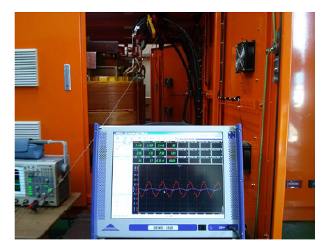
Figure 4. Measurement as shown on the inverter output side.

Table 3. MicroGrid’s building blocks.
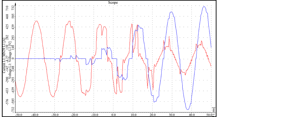
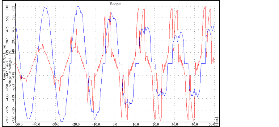
Figure 5. Voltage/current waveforms during WT’s startup (soft starter in operation, Red: Voltage, Blue: Current).

Figure 6. Voltage/current waveforms during WT’s startup (soft starter not in operation, Red: Voltage, Blue: Current).
starter was not used. Figure 7 shows the waveforms of voltage and current after WT successfully started and shifted to power generation mode. It can be seen that, even though startup succeeded, the current periodically fluctuates and oscillates.
Representing Figure 7 with active power and reactive power produces Figure 8. Note that active power and reactive power oscillate with around 1 [Hz]. The oscillation range of active power is approximately −120 [kW]~ + 100 [kW], where “−(minus)” means that it operated as motor (i.e., consumed energy). This suggests that WT, after shifting to power generation mode, did not work as generator only but alternately worked as both generator and motor.
The oscillation range of the reactive power is approximately –70 [kVAr] - −470 [kVAr], where “−(minus)” means that WT continuously absorbed the reactive power. This is an inevitable result considering the fact that

Figure 7. Voltage/current waveforms during WT’s power generation (Red: Voltage, Blue: Current).

Figure 8. Voltage/current waveforms during WT’s power generation (Blue: Active Power, Red: Reactive Power).
WT adopted an induction machine. As active power oscillates by 1 Hz unit, however, reactive power is continuously oscillating proportionately as well.
4. Analysis through PSCAD/EMTDC Simulation
In this section, to analyze Section 3.1’s phenomenon, the isolated MicroGrid’s building block was modeled using PSCAD/EMTDC. First, modeling was done under the same environment as the condition used in the test. To find out the causal analysis and improvement method, simulations were done by alternating various conditions.
4.1. Modeling Using PSCAD/EMTDC
WT, soft starter, battery, inverter, distribution line, transformer, etc., were modeled using PSCAD/EMTDC. The result of modeling can be seen in Figure 9. At this time, the modeling parameter used Table 3 and actual data, and modeling was done based on the condition wherein voltage waveform distortion and output oscillation occurred as in the actual situation. The inverter was modeled as PWM inverter capable of CVCF operation. Dummy load was modeled into the inverter.
The simulation process was modeled similar to the actual test conditions. In the actual test procedure, the inverter is first started, and the line and transformer are then supplied with power. Subsequently, if optimal wind speed is reached, the WT blades begin to rotate; when their rotation speed reaches around 1000 rpm, the soft starter operates. It takes around 0.2 seconds (10 - 12 cycles) for the soft starter’s rotation speed to reach the rated value (around 1200 rpm). Afterward, the soft starter is bypassed, and WT shifts to power generation mode. Table 4 summarizes this together with the simulation processes.
4.2. Simulation Result during WT Startup
To analyze the voltage distortion phenomenon during WT startup, the soft starter was modeled to simulate the phenomenon during startup. Figure 10 shows the waveform generated when WT was started using soft starter, whereas Figure 11 illustrates the waveform generated when WT was started without using soft starter. Figure 10 shows that the voltage waveform is significantly distorted, and that overvoltage is being generated. On the contrary, Figure 11 illustrates that the situation is alleviated considerably compared to the case in Figure 10.
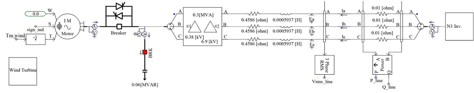
Figure 9. Simulation model using PSCAD/EMTDC.
This configuration denotes the fixed-speed wind turbine with an asynchronous squirrel cage induction generator (SCIG) directly connected to the grid via a transformer. Since the SCIG always draws reactive power from the grid, this configuration uses a capacitor bank for reactive power compensation. A smoother grid connection is achieved by using a soft-starter. Regardless of the power control principle in a fixed-speed wind turbine, the wind fluctuations are converted into mechanical fluctuations and consequently into electrical power fluctuations. In the case of a weak grid, these can yield voltage fluctuations at the point of connection. Because of these voltage fluctuations, the fixed-speed wind turbine draws varying amounts of reactive power from the utility grid (unless there is a capacitor bank), which increases both the voltage fluctuations and the line losses. Thus the main drawbacks of this concept are that it does not support any speed control, it requires a stiff grid [7] .
Note: SCIG = squirrel cage induction generator; WRIG = wound rotor induction generator; PMSG = permanent magnet synchronous generator; WRSG = wound rotor synchronous generator. The broken line around the gearbox in the Type D configuration indicates that there may or may not be a gearbox.
2.1.2. Type B: Limited Variable Speed
This configuration corresponds to the limited variable speed wind turbine with variable generator rotor resistance. The generator is directly connected to the grid. A capacitor bank performs the reactive power compensation. A smoother grid connection is achieved by using a soft-starter. The total rotor resistance is controllable. This way, the power output in the system is controlled [7] .
2.1.3. Type C: Variable Speed with Partial Scale Frequency Converter
This configuration, known as the doubly fed induction generator (DFIG) concept, corresponds to the limited variable speed wind turbine with a wound rotor induction generator (WRIG) and partial scale frequency converter (rated at approximately 30% of nominal generator power) on the rotor circuit The partial scale frequency converter performs the reactive power compensation and the smoother grid connection. Typically, the speed range comprises synchronous speed 40% to 30% [7] .
2.1.4. Type D: Variable Speed with Full-Scale Frequency Converter
This configuration corresponds to the full variable speed wind turbine, with the generator connected to the grid through a full-scale frequency converter. The frequency converter performs the reactive power compensation and the smoother grid connection. The generator can be excited electrically [wound rotor synchronous generator (WRSG) or WRIG) or by a permanent magnet [permanent magnet synchronous generator (PMSG)] [7] .
2.2. Using the Wind Turbine Generator with Isolated MicroGrid
This section summarizes the points to be considered when using the wind turbine generator in the small-scale power system.
2.2.1. Penetration Level
When incorporating renewable-based technologies into isolated power supply systems, the amount of energy that will be obtained from the renewable sources will strongly influence the technical layout, performance and economics of the system. For this reason, it is necessary to explain two new parameters—the instantaneous and average power penetration of wind—as they help define system performance [7] .
The average and peak penetration of renewable generation in a hybrid power system can be defined as shown in Equations (1) and (2) [8] .
 (1)
(1)
 (2)
(2)
In [9] , these definitions are used to categorize hybrid power systems into three classes; low, medium and high penetration, as shown for reference in Table2
2.2.2. Hybrid Power System
The electric power production cost for the diesel power plants located in islands or remote areas-depending on their scale and distance from land can rise up to 10 times that of the large-scale electrical power system [10] . To reduce the electric power production cost, renewable energy systems such as wind turbine generators or photo
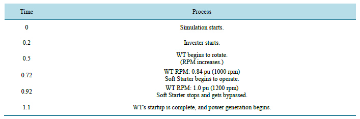
Table 4. Simulation process.
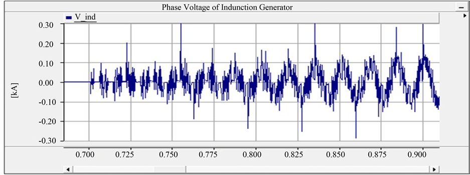
Figure 10. Voltage waveform with soft starter.

Figure 11. Voltage waveform without soft starter.
This means that the voltage waveform distortion during WT’s initial startup is caused by the soft starter.
4.3. Simulation Result during WT’s Power Generation
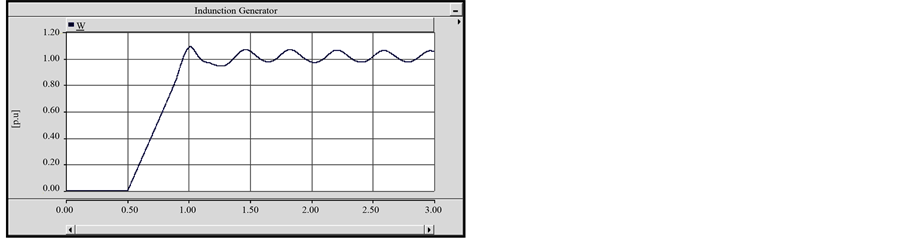
To analyze the cause of the output oscillation phenomenon during WT’s power generation, simulation was first done to get the same result as the existing one. Figure 12(b) is the current status of WT output, and we can see that it is similar to Figure 7’s result. To find out the condition for WT’s normal operation, simulations were done by alternating various conditions. As a result, the oscillation phenomenon was confirmed to have been alleviated or aggravated according to the inverter controller’s gain. The oscillation phenomenon can be seen to have been alleviated especially according to the extent of P (proportional) gain; this means that the inverter’s frequency tracking performance is currently set low. Table 5 shows the controller’s gain in current state and improved state.
Figure 12 confirms that the controller’s low gain caused the frequency oscillation, and that this in turn oscillated WT’s rpm and voltage, too. Figure 13 verifies that the controller tuning improved its gain, and that the oscillation phenomenon was removed. Frequency can also be confirmed to be maintained in stabilized condition at 60 Hz, with WT’s rpm maintained well at the rated value.
Based on the simulation result above, the system frequency oscillation and WT’s output oscillation (motoring ↔ generation) phenomena can be analyzed. Specifically, the WT considered in this paper is configured as squirrel cage induction generator (Figure 2’s A type), and the induction machine can work either as generator or motor depending on its rotation speed and torque in contrast to the synchronous speed [12] . It is working as a motor if it rotates slower than the synchronous speed and as generator if faster. The WT considered in this paper
 (a)
(a)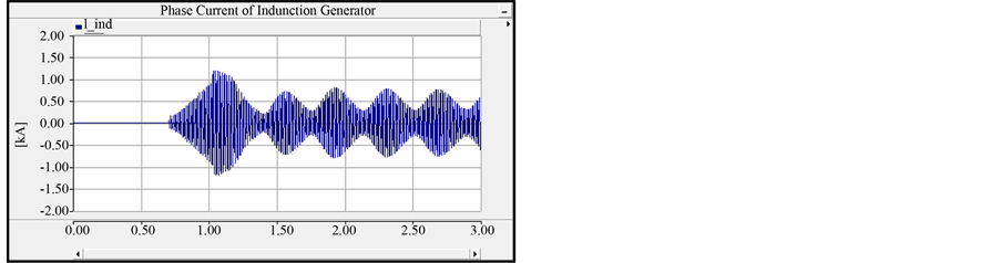 (b)
(b)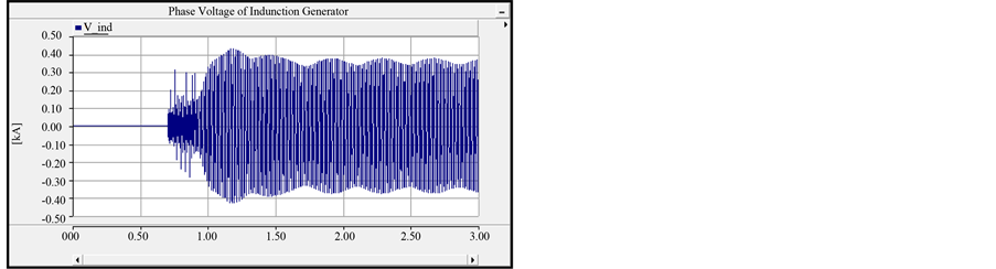 (c)
(c)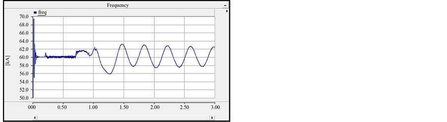 (d)
(d)
Figure 12. Simulation results for the current state. (a) WT’s RPM; (b) WT’s phase current waveform; (c) WT’s phase current waveform; (d) Frequency of MicroGrid.
 (a)
(a) (b)
(b) (c)
(c)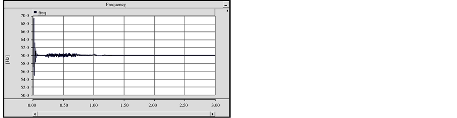 (d)
(d)
Figure 13. Simulation results for the inverter’s gain change. (a) WT’s RPM; (b) WT’s phase current waveform; (c) WT’s phase current waveform; (d) WT’s phase current waveform.
has rated speed of 1211 rpm and synchronous speed of 1200 rpm during power generation. In case WT’s system frequency increases to 61 Hz for some reason (ex. frequency fluctuation at the inverter), the synchronous speed at this time becomes 1220 rpm, but the wind turbine’s rotation speed remains at 1211 rpm, making WT work as
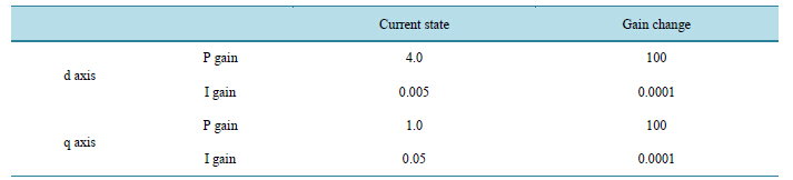
Table 5. Inverter controller’s gain.
a motor. If the synchronous speed increases from 1200 rpm to 1220 rpm according to the system frequency’s increase, the generator’s slip (difference between synchronous speed and operation speed) is reduced, resulting in decreased torque. Since the generator’s torque acts as a brake against the wind turbine’s torque, the reduction of such torque accelerates the wind turbine’s rotation speed and increases the generator’s rpm, which in turn increases the slip again and results in the generator’s torque being increased to the original state. In other words, it gets to act as generator again.
5. Conclusions
This study presented the survey data for the voltage and frequency maintenance problem in Isolated MicroGrid composed of WT and battery system and analyzed the causes using PSCAD/EMTDC. The isolated MicroGrid considered in this paper has its voltage waveform distorted during WT’s startup; this in turn generates low voltage and over voltage. Likewise, after shifting to generation mode, the output oscillation phenomenon makes it difficult to maintain system frequency, and normal operation becomes difficult.
As a result of simulation using PSCAD/EMTDC, the voltage waveform distortion during WT’s startup was found to be due to the soft starter used at the time. Its solutions could include improving the battery inverter’s harmonics handling performance or installing APF (Active Power Filter). WT’s output oscillation phenomenon was analyzed to be due to the improper setting of inverter controller’s gain, which caused WT to alternate between generation mode and motor mode.
Due to its characteristics, the SCIG-type WT can operate only at high starting current and within a very narrow frequency domain. This means that using the SCIG-type WT in isolated MicroGrid requires inverters with very large capacity and high performance. Thus, it is important to choose WT with proper type and capacity when designing isolated MicroGrid.
Finally, we will change the grid forming inverter as more proper type for isolated MicroGrid.
Acknowledgements
This work was supported by Korea Institute of Energy Technology Evaluation and Planning (KETEP) grant funded by Korea Government Ministry of Knowledge Economy (No. 20123010020080).
References
- Hatziargyriou, N.D., Asano, H., Iravani, R. and Marnay, C. (2007) Microgrids. IEEE Power & Energy, 5, 78-94.http://dx.doi.org/10.1109/MPAE.2007.376583
- Hatziargyriou, N.D. (2008) Microgrids. IEEE Power & Energy, 6, 26-29.
- Venkataramanan, G. and Marnay, C. (2008) A Larger Role for Microgrids. IEEE Power & Energy, 6, 78-82.http://dx.doi.org/10.1109/MPE.2008.918720
- Asmus, P. (2009) Microgrids, Islanded Power Grids and Distributed Generation for Community, Commercial, and Institutional Applications. Navigant Research, Boulder. http://www.navigantresearch.com
- Lasseter, R.H. (2002) Microgrids. IEEE PES Winter Meeting, New York City, 27-31 January 2002, 305-306.
- Kojima, T. and Fukuya, Y. (2011) Microgrid System for Isolated Islands. Fuji Electric Review, 57, 125-130.
- Ackermann, T. (2005) Wind Power in Power Systems. Wiley, Hoboken, 55-59. http://dx.doi.org/10.1002/0470012684
- Prull, D.S. (2008) Design and Integration of an Isolated MicroGrid with a High Penetration of Renewable Generation. Doctor’s Thesis, University of California, Berkeley.
- Baring-Gould, I.E., et al. (2004) Worldwide Status of Wind-Diesel Applications. 2004 Doe/Awea/Canwea Wind-Diesel Workshop, Technical Report, National Renewable Energy Laboratory, Cole Blvd.
- KEPCO (2012) Report for the Prime Cost Report of Diesel Power Plant. KEPCO, Seoul.
- Pingree, B. (2011) A New Isolated Grid Paradigm. 2011 International Wind-Diesel Workshop. Girdwood Alaska, 8-11 March 2011, 8-10.
- Chapman, S.J. (2001) Electric Machinery Fundamentals. McGraw-Hill, New York.
- Freris, L. and Infield, D. (2011) Renewable Energy in Power Systems. John Wiley & Sons, Hoboken.
- Chae, W. (2013) SCIG Type Wind Turbine’s Characteristic in Island MicroGrid. ISGC & E, Jeju.
NOTES

*Corresponding author.