Smart Grid and Renewable Energy
Vol.1 No.3(2010), Article ID:3325,12 pages DOI:10.4236/sgre.2010.13018
Design and Testing of Three Earthing Systems for Micro-Grid Protection during the Islanding Mode
![]()
Environmental Energy Engineering, Department of Electronics & Information Engineering, Tokyo University of Agriculture and Technology, Nakamachi, Koganei-shi, Tokyo, Japan.
Email: r_m_kamel@yahoo.com, a.chaouachi@gmail.com, bahman@cc.tuat.ac.jp
Received October 26th, 2010; revised November 19th, 2010; accepted November 21st, 2010
Keywords: Micro grid protection, earthing systems, fault current, touch voltage, micro sources and inverters
ABSTRACT
This paper presents and tests three earthing systems (TT, TN and IT) for Micro-Grid (MG) protection against various fault types when the MG transferred to the islanding mode. The main contribution of this work is including the models of all micro sources which interfaced to the MG by power electronic inverters. Inverters in turns are provided with current limiters and this also included with the inverter models to exactly simulate the real situation in the MG during fault times. Results proved that the most suitable earthing system for MG protection during the islanding mode is the TN earthing system. That system leads to a suitable amount of fault current sufficient to activate over current protection relays. With using TN earthing system, touch voltages at the faulted bus and all other consumer’s buses are less than the safety limited values during islanding mode. For the two others earthing systems (TT and IT), fault currents are small and nearly equal to the over load currents which make over current protection relay can not differentiate between fault currents and overload currents. All models of micro sources, earthing systems, inverters and control schemes are built using Matlab®/Simulink® environment.
1. Introduction
The earthing of an electricity supply network requires its network plant and customer electrical equipment to be connected to the earth in order to promote safety and reduce the possibilities of damage to equipment. Effective earthing prevents long term over voltages and minimizes risk of electric shock hazards. Earthing also provides a predetermined path for earth leakage currents, which are used to disconnect the faulty plant or circuit by operating the protective devices. Micro-Grid (MG) is a unique example of a distribution system and needs careful assessment before deciding on its earthing system.
A MG consists of a cluster of micro sources, energy storage systems (e.g. flywheel, battery, ultra capacitor, …) and loads, operating as a single controllable system. The voltage level of the MG is 400 Volt or less. The architecture of the MG is formed to be radial with a number of feeders. The MG often provides both electricity and heat to the local area. The MG can be operated in both gridconnected mode and islanded mode as described in details on our previous research [1-10].
The micro sources are usually made of many new technologies, e.g. micro gas turbine, fuel cell, photovoltaic system and several kinds of wind turbines. The energy storage system often is a flywheel system. The micro sources and flywheel are not suitable for supplying energy to the grid directly [11]. They have to be interfaced with the grid through an inverter stage. The use of power electronic interfacing in the MG thus leads to a series of challenges in the design and operation of the MG. One of the major challenges is protection design of the MG to comply with the relevant national Distribution Codes and to maintain the safety and stability of the MG during both grid-connected mode and islanded mode.
However, the inverter based MG can not normally provide the required levels of short circuit current. In extreme cases, the fault current contribution from the micro sources may only be twice load current or less [12,13]. Some over current sensing devices will not even respond to this level of over current. In addition, the over/under voltage and frequency protection may fail in detecting faults on the MG due to the voltage and frequency control of the MG. That unique nature of the MG requires a fresh look into the design and operation of the protection. This is the task of this manuscript.
This manuscript presents three earthing systems for MG protection during the islanding mode. The two main contributions of this manuscript are: 1) consider the models of all micro sources (and their inverters) installed in the MG and 2) Included current limiter with each inverter inside the MG to simulate exactly the real situation during fault time.
Three earthing systems are implemented and tested for MG protection. Comparison between the performance of the three systems is highlighted. The most suitable earthing system is deduced from the comparison.
To conduct the proposed study, this manuscript is organized as follow: Section 2 describes the three designed earthing systems. Section 3 presents the fault behavior in each earthing system plus advantages and disadvantages of each one. MG network included all micro sources, inverters and earthing system is presented in Sction 4. Section 5 shows the results obtained with applying the three earthing systems and the sequence of the events occur with each one. Conclusions are indicated in Sction 6.
2. Types of Earthing Systems
A low voltage (LV) distribution system may be identified according to its earthing system. These are defined using the five letters T (direct connection to earth), N (neutral), C (combined), S (separate) and I (isolated from earth). The first letter denotes how the transformer neutral (supply source) is earthed while the second letter denotes how the metalwork of an installation (frame) is earthed. The third and fourth letters indicate the functions of neutral and protective conductors respectively. There are three possible configurations [14]:
1) TT: transformer neutral earthed and frame earthed.
2) TN: transformer neutral earthed, frame connected to neutral.
3) IT: unearthed transformer neutral, earthed frame.
The TN system includes three sub-systems: TN-C, TN -S and TN-C-S, as discussed in the following sub-sections.
2.1. TT Earthing System
In this system, the supply source has a direct connection to earth. All exposed conductive parts of an installation also are connected to an earth electrode that is electrically independent of the source earth. The structure of TT system is shown in Figure 1 [15].
2.2. TN Earthing System
In TN earthing system, the supply source (transformer neutral) is directly connected to the earth and all exposed conductive parts of an installation are connected to the neutral conductor. Safety of personnel is guaranteed, but that of property (fire, damage to electrical equipment) is less so. The three sub-systems in TN earthing system are described below with their key characteristics.
2.2.1. TN-C Earthing System
As shown in Figure 2(a), TN-C system has the following features:
1) Neutral and protective functions are combined in a single conductor throughout the system. (PEN—Protective Earthed Neutral).
2) The supply source is directly connected to earth and all exposed conductive parts of an installation are con-
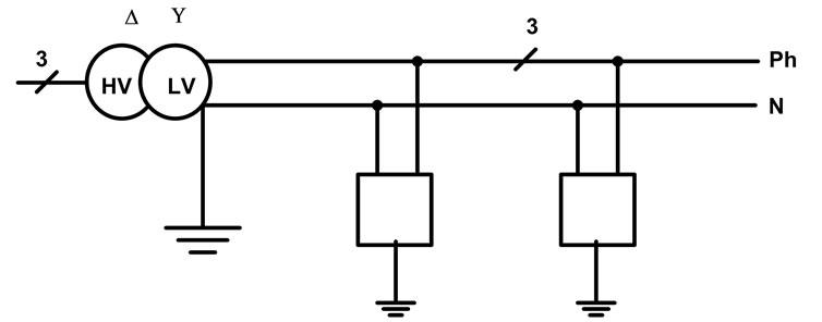
Figure 1. TT earthing system configuration. (Ph is the phase wire, N is the neutral wire).
 (a)
(a) (b)
(b) (c)
(c)
Figure 2. (a) TN-C earthing system configuration. (Ph is phase symbol; PEN is the protective earthed and neutral wire); (b) TN-S earthing system configuration. (Ph is phase symbol, N is the neutral wire and PE is the protective earthed wire); (c) TN-C-S earthing system. (Ph is phase symbol, N is the neutral wire and PE is the protective earthed wire).
nected to the PEN conductor.
2.2.2. TN-S Earthing System
The TN-S earthing system architecture is shown in Figure 2(b) and has the following features:
1) The TN-S earthing system has separate neutral and protective conductors throughout the system.
2) The supply source is directly connected to earth. All exposed conductive parts of an installation are connected to a protective conductor (PE) via the main earthing terminal of the installation.
2.2.3. TN-C-S Earthing System
TN-C-S earthing system configuration is shown in Figure 2(c) and has the following features:
1) Neutral and protective functions are combined in a single conductor in a part of the TN-C-S system. The supply is TN-C and the arrangement in the installation is TN S.
2) Use of a TN-S downstream from a TN-C.
3) All exposed conductive parts of an installation are connected to the PEN conductor via the main earthing terminal and the neutral terminal, these terminals being linked together.
2.3. IT Earthing System
In this system, the supply source is either connected to earth through deliberately introduced high earthing impedance (Impedance earthed IT system) or is isolated from earth as shown in Figure 3. All exposed conductive parts of an installation are connected to an earth electrode.
Every exposed-conductive part shall be earthed to satisfy the following condition for each circuit [16]:
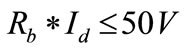 (1)
(1)
Where:
Rb: Resistance of the earth electrode for exposed conductive-parts.
Id: Fault current which takes account of leakage currents and the total earthing impedance of the electrical installation.
3. Fault Behavior and Characteristics of Different Earthing Systems
An insulation failure in an electrical installation presents hazards to humans and equipments. At the same time it may cause unavailability of electrical power. The fault currents and voltages differ from one earthing system to another as described in the following sub sections.
3.1. Fault Behavior in the TN Earthing System
Figure 4 shows fault behavior in the TN earthing system and the path of fault current. When an insulation fault is present, the fault current Id is only limited by the impedance of the fault loop cables. Short circuit protection devices (circuit breaker or fuses) generally provide protection against insulation faults, with automatic tripping according to a specified maximum breaking time (depending on phase-to-neutral voltage Uo). Typical breaking times in the TN earthing system are tabulated in Table 1 according to IEC 60364 (UL is the limited safety voltage).
3.1.1. Advantages of the TN Earthing System
1) The TN earthing system always provides a return path for faults in the LV grid. The grounding conductors at the transformer and at all customers are interconnected. This ensures a distributed grounding and reduces the risk of a
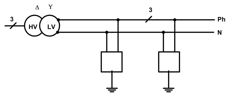
Figure 3. IT earthing system.

Figure 4. A fault behavior in the TN-S earthing system. (Id is the fault current; Rd is the conducting parts resistance, Ud is the touch voltage).

Table 1. Braking time in TN system (taken from IEC 60364 tables 41 and 48 A).
customer not having a safe grounding.
2) Lower earthing resistance of the PEN conductor.
3) TN earthing system has the advantage that in case of an insulation fault, the fault voltages (touch voltages) are generally smaller than in TT earthing systems. This is due to the voltage drop in the phase conductor and the lower impedance of the PEN conductor compared with the consumer earthing electrodes in TT systems.
4) No overvoltage stress on equipment insulation.
5) TN-S system has the best Electromagnetic Compatibility (EMC) properties for 50 Hz and high frequency currents, certainly when LV cables with a grounded sheath is applied.
6) TN earthing system could work with simple over current protection.
7) High reliability of disconnection of a fault by over current devices (i.e. fault current is large enough to activate the over current protection devices).
3.1.2. Disadvantages of the TN Earthing System
1) Faults in the electrical network at a higher voltage level may migrate into the LV grid grounding causing touch voltages at LV customers.
2) A fault in the LV network may cause touch voltages at other LV customers.
3) Potential rise of exposed conductive parts with the neutral conductor in the event of a break of the neutral network conductor as well as for LV network phase to neutral and phase to ground faults and MV to LV faults.
4) The utility is not only responsible for a proper grounding but also for the safety of customers during disturbances in the power grid 5) Protection to be fitted in case of network modification (increase of fault loop impedance).
6) TN-C system is less effective for Electromagnetic Compatibility (EMC) problems.
3.2. Fault Behavior in the TT Earthing System
Figure 5 explains fault behavior in the TT earthing system. When an insulation fault occurs, the fault current Id is mainly limited by the earth resistances (Ra and Rb). At least one residual current device (RCD) must be fitted at the supply end of the installation. In order to increase availability of electrical power, use of several RCDs ensures time and current discrimination on tripping [16].
3.2.1. Advantages of the TT Earthing System
1) The most commonly found earthing system.
2) Faults in the LV and MV grid do not migrate to other customers in the LV grid.
3) Good security condition, as the potential rise of the grounded conductive part must be limited at 50 V for a fault inside the installation and at 0 V for a fault on the network.
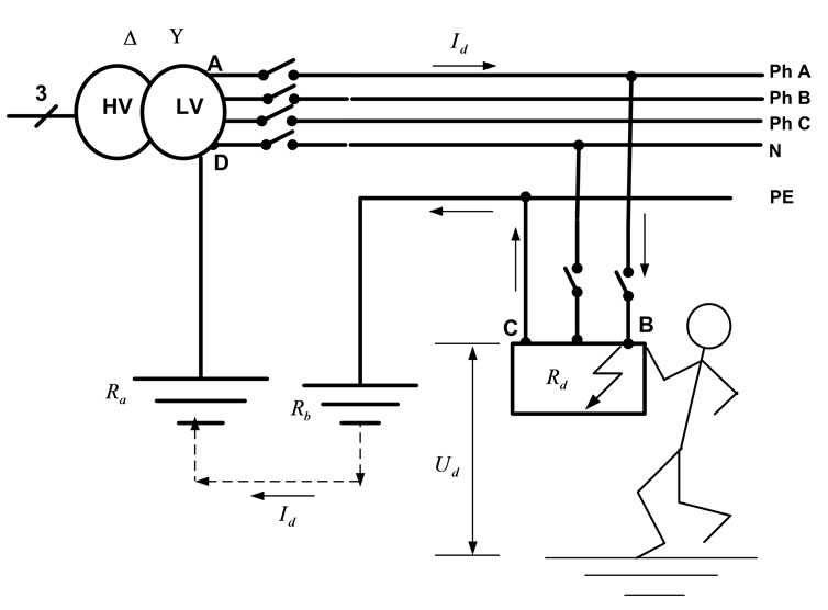
Figure 5. The fault behavior in the TT earthing system. (Id is the fault current; Rd is the conducting parts resistance, Ud is the touch voltage, Ra and Rb are the resistances of the earthing electrodes at main supply and consumers).
4) Simple earthing of the installation and the easiest to implement.
5) No influence of extending the network.
3.2.2. Disadvantages of the TT Earthing System
1) Each customer needs to install and maintain its own ground electrode. Safety and protection depends on the customer, thus complete reliability is not assured.
2) High over voltages may occur between all live parts and between live parts and PE conductor.
3) Possible overvoltage stress on equipment insulation of the installation.
3.3. Fault Behavior in the IT Earthing System
3.3.1. First Fault in the IT Earthing System
Figure 6 shows the occurrence of the first fault in the IT earthing system. The fault voltage is low and not dangerous. Therefore it is not necessary to disconnect an installation in the event of a single fault. However it is essential to know that there is a fault and need to track and eliminate it promptly, before a second fault occurs. To meet this need the fault information is provided by an Insulation Monitoring Device (IMD) monitoring all live conductors, including the neutral [16]. When the neutral is not distributed (three-phase three-wire distribution), the following condition must be satisfied [16]:
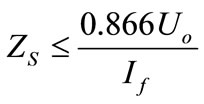 (6.2)
(6.2)
Where:
ZS = Earth fault loop impedance comprising the phase conductor and the protective conductor.
If = fault current.
Uo = the supply phase to neutral voltage.
When the neutral is distributed (three-phase four-wire distribution and single phase distribution), the following condition must be satisfied [16]:
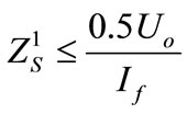 (6.3)
(6.3)
Where:
 = Earth fault loop impedance comprising the neutral conductor and the protective conductor.
3.3.2. Second Fault in the IT Earthing System
Figure 7 shows the occurrence of the second fault in the IT earthing system. Maximum disconnection times for the IT earthing system are given in Table 2 (as in IEC 60364 tables 41 B and 8 A) [16].
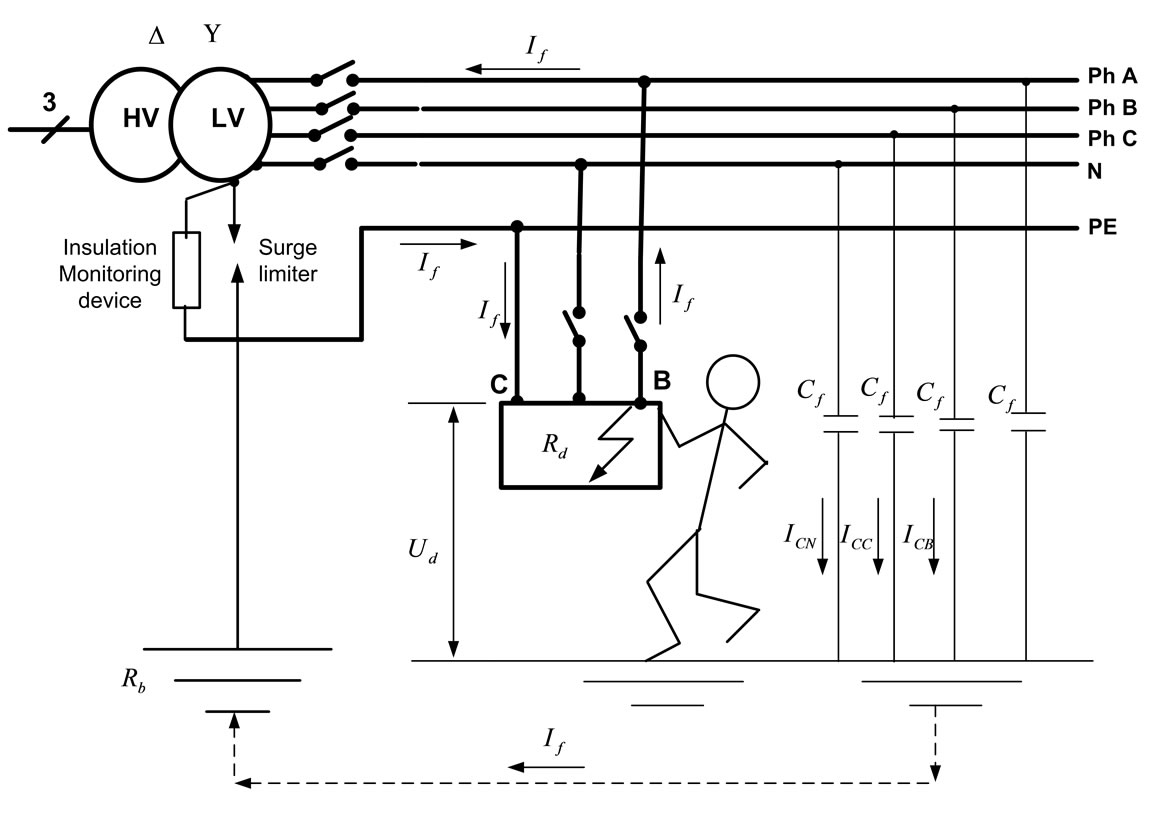
Figure 6. First insulation fault current in the IT earthing system. (If is the fault current, Rd is the conducting part resistance, Cf is the charging capacitance, IC is the charging current).

Figure 7. Second insulation fault current in IT system (distributed neutral).
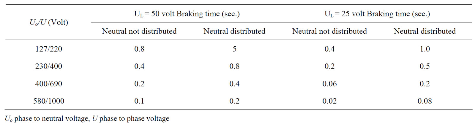
Table 2. Maximum disconnection time in the IT earthing system (second fault)
3.3.2.1. Advantages of the IT Earthing System
1) The IT earthing system used when safety of persons and property, and continuity of service are essentials.
2) Fault current is zero or very small value.
3.3.2.2. Disadvantages of the IT Earthing System 1) Insulation Monitoring Device (IMD) is required for monitoring all live conductors to can discover the first fault occurrence.
2) High voltage stress on the equipments after the first fault occurrence (phase voltage will multiply by 1.71 and became equal to line voltage).
3) Overvoltage protection should be used to protect sensitive voltage equipment against the high voltage stress after the first fault occurrence.
4. Architecture of the Studied Micro Grid
Figure 8 shows single line diagram of the studied MG. It consists of 7 buses. Flywheel (storage device) with rating 30 kW/0.5 kWh is connected at bus 1. Fixed speed wind generation system (10 kW) is connected to bus 2. Two photovoltaic panels with rating 10 kW and 3 kW are connected to buses 4 and 5, respectively. Single Shaft Micro Turbine (SSMT) with rating 25 kW is connected to bus 6. Bus 7 is provided with Solid Oxide Fuel Cell (SOFC) with rating 20 kW. All MG’s components (micro sources, inverters with different control schemes, loads, …) are modeled in details in our previous research [1-10].
The developed model is general and can be used to investigate the behavior of the MG under all fault types. The fault presented in this study is single phase to ground fault, which is the most common fault in the consumer premises. In the simulation model, micro sources are taken into account. It is assumed that all power electronic inverters which used to interface micro sources are equipped with current limiters to limit the fault current to about 150% of the inverter’s full load current. This current limiter is included in each inverter circuit to protect inverter semiconductor switches from damages and represent the real situation accurately. In Figure 8, the studied MG is illustrated. Line parameters are tabulated in Table 3 [17-21].
Complete Matlab®/Simulink® model which built for testing the three earthing systems is shown at the end of this paper (Figure 17).
5. Performance of the Three Earthing Systems in MG Protection during the Islanding Mode
During this case, MG operates in the islanding mode. Flywheel interfaced by the voltage source inverter (VSI) at bus # 1 represents the slack (reference) bus for the MG. The studied disturbance is a short circuit (single phase to ground fault) occurs at the consumer feeds at bus # 2. Fault current, touch voltages at all consumers, voltage of healthy phases and voltage of the main transformer neutral point are shown in the following figures (Figure 9 to Figure 16) when the three earthing systems (TN-S, TT and IT) are employed in the MG.
From the results which are presented in the previous figures, the following points can be concluded:
1) Figure 9 shows the fault current. When TN-S earthing system is used, the fault current (maximum value) increases to about 400 A. On the other hand, with using TT and IT earthing systems, the fault current not different more than the steady state value and the over current protection devices can not differentiate between the fault current and the overload current inside the MG. This fact make TN-S earthing system is more suitable than TT and IT earthing system in MG protection.
2) Figure 10 shows the touch voltage at the faulted bus. As shown, with TN-S earthing system, touch voltage (maximum value) about 30 Volt, while with using TT system, touch voltage (maximum value) reach to 300 Volt (higher than the safety value) and it is dangerous for persons. This is another advantage makes TN-S earthing system is the more suitable earthing system for MG. When IT earthing system is used, touch voltage at the faulted bus not increase than zero. Also as shown in Figure 11 to Figure 14, touch voltages at all buses and consumers with TN-S earthing system not increase than 15 Volt, which prove that TN-S is still suitable. When using TT and IT earthing systems, the touch voltages at all unfaulted buses not increase than zero value which proves that with using TT and IT earthing system, fault not transfer from the consumer to another consumer.
3) Figure 15 shows the voltage of unfaulted (healthy) phases (at bus #2). With using IT earthing system, voltages of the unfaulted phases increase to the line value (220 V increase to 380 V) which causes high voltage stress on the equipments connected to the two healthy phases. On the other hand, with using TT earthing system, voltages of the healthy phases has small drop than the steady state value. When TN-S system is used, those voltages dropped to a small value.
4) Figure 16 shows the voltage of the neutral point of the main transformer. As shown, with TN-S and TT earthing systems, the neutral point voltage increases to a small value. On the other hand, with using IT earthing system, the neutral point voltage equal to the phase voltage and this is the reasons of voltage rising of unfaulted phases shown in Figure 15.
5) In conclusions, TN-S system represents the most
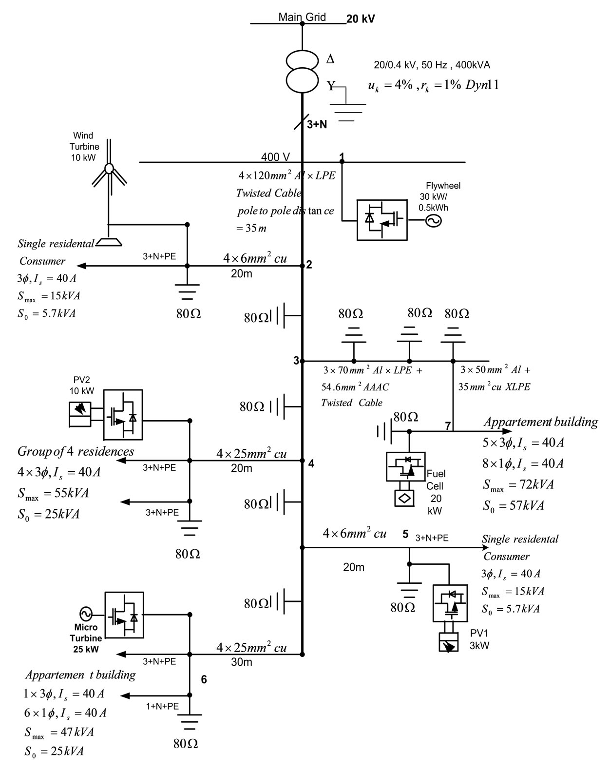
Figure 8. Single line diagram of the studied MG.
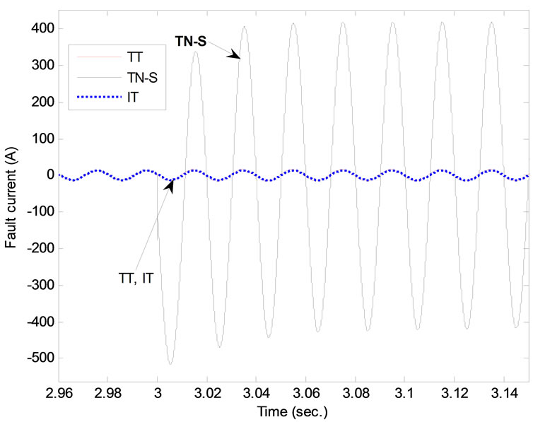
Figure 9. Fault current with the three earthing systems during islanding mode.
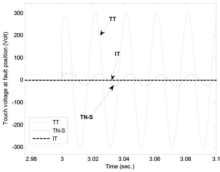
Figure 10. Touch voltage at consumer of bus # 2 (faulted bus).
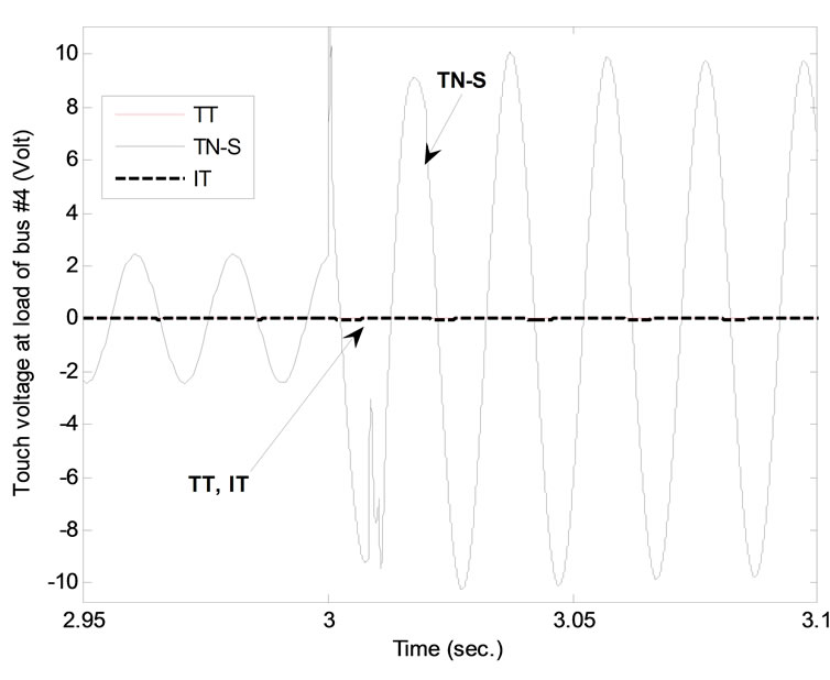
Figure 11. Touch voltage at consumer of bus # 4.
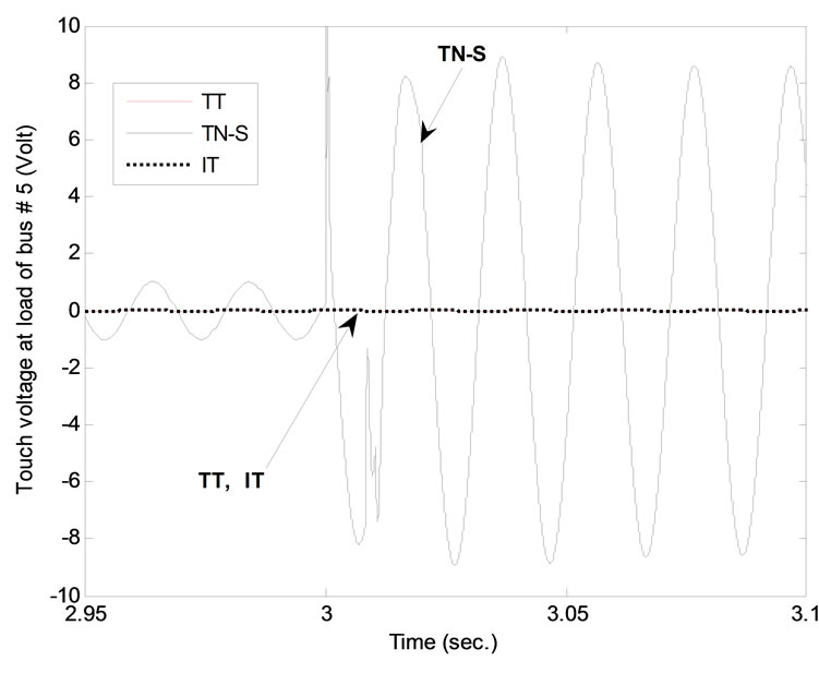
Figure 12. Touch voltage at consumer of bus # 5.
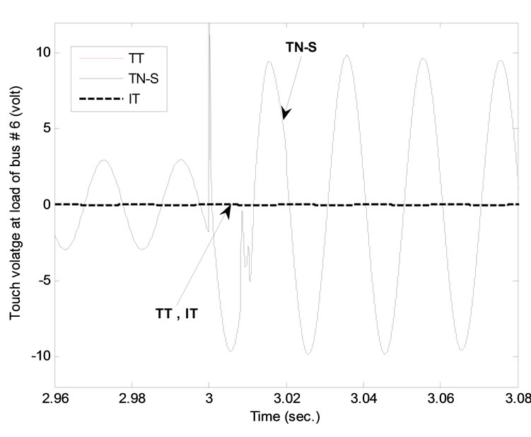
Figure 13. Touch voltage at consumer of bus # 6.
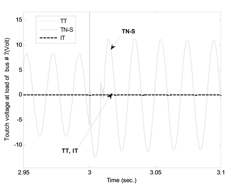
Figure 14. Touch voltage at consumer of bus # 7.
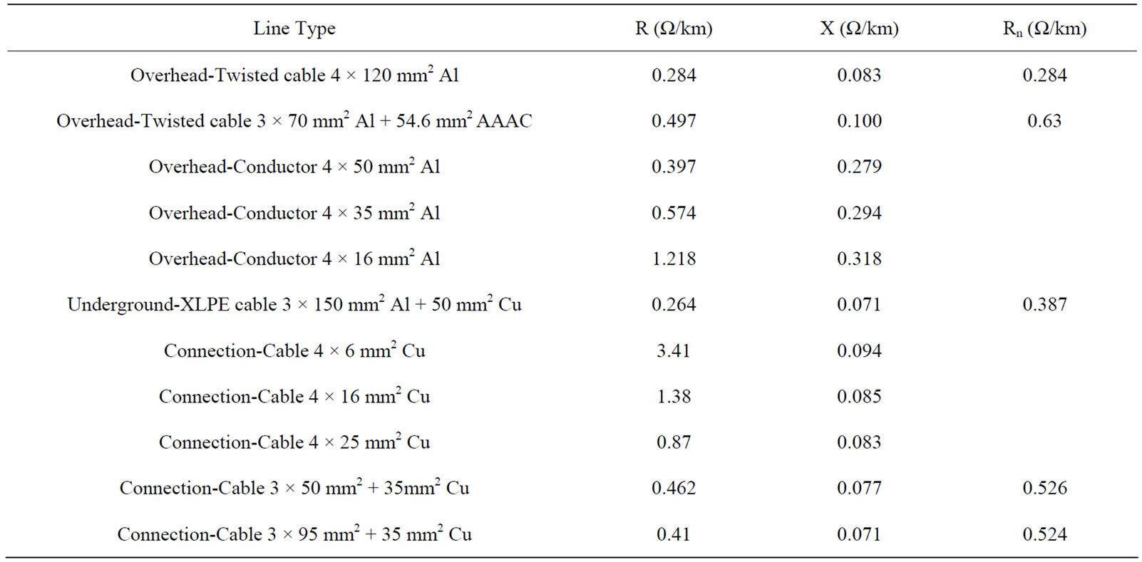
Table 3. MG line parameters.

Figure 15. Voltage of healthy phases (at bus # 2).
suitable earthing system for MG during the islanding mode. With that system, simple over current protection devices are suitable to clear the fault in MG. However, with the other two earthing systems (TT and IT), over current protection devices can not differentiae between the fault current and overload current inside the MG.
6. Conclusions
In this paper, three earthing systems are applied to protect the MG against different faults during the islanding mode. It is observed from the results that the most suitable system is the TN earthing system. This is because fault current with TN earthing system is sufficient enough to activate the protection relay. On the other hand,
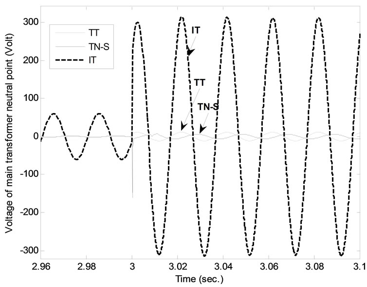
Figure 16. Main transformer neutral point’s voltage.
for the other two earthing systems (TT and IT), protection relay can not differentiate between the fault current and overload current. Also, touch voltages at all consumers with using TN system are small and less than the safety limit value. While, with TT earthing system, touch voltage at the faulted bus is very high and higher than the safety limit value. With using IT earthing system, voltages of the healthy phases will nearly doubled (220 V became 380 V) and causes voltage stress for all equipments which are feed from the healthy phases. In conclusions, the TN earthing system is the most superior system for MG protection from the point of view of fault current and touch voltages. From this paper results, TN earthing system is the most recommended system for MG protect-

Figure 17. Matlab®/Simulink® Developed model for MG with the erathing system.
tion during the islanding mode. Author’s next step research is applying and testing the performance of those three earthing systems in MG protection during the connected mode.
REFERENCES
- R. M. Kamel and B. Kermanshahi, “Design and Implementation of Models for Analyzing the Dynamic Performance of Distributed Generators in the Micro Grid Part I: Micro Turbine and Solid Oxide Fuel Cell,” Scientia Iranica, Transactions D, Computer Science & Engineering and Electrical Engineering, Vol. 17, No. 1, June 2010, pp. 47-58.
- R. M. Kamel, A. Chaouachi and K. Nagasaka, “MicroGrid Dynamic Response Enhancement Using New Proportional Integral Wind Turbine Pitch Controller and Neuro-fuzzy Photovoltaic Maximum Power Point Tracking Controller,” Electric Power Components and Systems, Vol. 38, No. 2, 2010, pp. 212-239.
- R. M. Kamel, A. Chaouachi and K. Nagasaka, “Wind Power Smoothing Using Fuzzy Logic Pitch Controller and Energy Capacitor System for Improvement MicroGrid Performance in Islanding Mode,” Energy, Vol. 35, No. 4, March 2010, pp. 2119-2129.
- R. M. Kamel, A. Chaouachi and K. Nagasaka, “Micro Grid Transient Dynamic Response Enhancement during and Subsequent to Huge and Multiple Disturbances by Connecting It with Nearby Micro Grids,” International Journal of Sustainable Energy, Vol. 30, No. 4, August 2010, pp. 223-245.
- R. M. Kamel, A. Chaouachi and K. Nagasaka, “Effect of Micro Sources Failure on Dynamic Performance of the Micro-Grid during and Subsequent to Islanding Process,” ISESCO Science and Technology Vision, Vol. 6, No. 9, May 2010, pp. 2-10.
- R. M. Kamel, A. Chaouachi and K. Nagasaka, “Improvement of Transient Dynamic Response of MicroGrid Subsequent Islanding and Failure of Micro Sources by Connected Two Nearby Micro-Grids,” ISESCO Science and Technology Vision, Vol. 5, No. 8, 2009, pp. 46-55
- R. M. Kamel, A. Chaouachi and K. Nagasaka, “A Novel Pi Pitch Controller and Energy Capacitor System for Reducing Wind Power Fluctuations and Keeping MicroGrid Stable Subsequent Islanding Occurrence,” International Journal of Power & Energy Systems, Vol. 30, No. 2, April 2010, pp. 131-138.
- R. M. Kamel and B. Kermanshahi, “Optimal Size and Location of Distributed Generations for Minimizing Power Losses in a Primary Distribution Network,” Scientia Iranica, Transactions D, Computer Science & Engineering and Electrical Engineering, Vol. 16, No. 6, 2009, pp. 137-144.
- R. M. Kamel, A. Chaouachi and K. Nagasaka, “Carbon Emissions Reduction and Power Losses Saving besides Voltage Profiles Improvement Using Micro Grids,” Low Carbon Economy (Journal), Vol. 1, No. 1, 2010, pp. 1-7.
- R. M. Kamel, A. Chaouachi and K. Nagasaka, “Effect of Wind Generation System Rating on Transient Dynamic Performance of the Micro-Grid during Islanding Mode,” Low Carbon Economy (Journal), Vol. 1, No. 1, 2010, pp. 29-38.
- S. Barsali, et al., “Control Techniques of Dispersed Generators to Improve the Continuity of Electricity Supply,” Power Engineering Society Winter Meeting, Vol. 2, 27-37 January 2002, pp. 789-794.
- S. R. Wall, “Performance of Inverter Interfaced Distributed Generation,” Transmission and Distribution Conference and Exposition, Vol. 2, 28 October-2 November 2001, pp. 945-950.
- N. Jayawarna, et al., “Task TE2—Fault Current Contribution from Converters,” Micro Grids Draft Report for Task TE2.
- C. Prévé, “Protection of Electrical Networks,” by ISTE Ltd, book, 2006
- B. Lacroix and R. Calvas, “Earthing Systems in LV,” Schneider Electric’s Cahier’s Technique, Vol. 172, March 2002, pp. 1-30.
- N. Jayawarna, M. Lorentzou and S. Papathanassiou, “Review of Earthing in a Micro Grid,” MICROGRIDS Large Scale Integration of Micro-Generation to Low Voltage Grids Project, WORK PACKAGE E, April 2004.
- S. Papathanassiou, N. Hatziargyriou and K. Strunz, “A Benchmark Low Voltage Microgrid Network,” Proceedings of CIGRE Symposium Power Systems with Dispersed Generation,” Athens, April 2005, pp. 1-8.
- W. Xueguang, N. Jayawarna, Y. Zhang, N. Jenkins, J. P. Lopes, C. Moreira, A. Madureira and J. P. da Silva, “Protection Guidelines for a Micro-Grid,” Deliverable DE2 for EU MicroGrids Project, June 2005.
- “IEEE Guide for Safety in AC Substation Grounding,” IEEE Standard 80-2000 (Revision of IEEE Standard 80- 1986), 2000.
- “Urban Area Substation Analysis,” Safe Engineering Services & Technologies Ltd., Version 8, Montreal, Canada, January 2000.
- C. Marnay, F. J. Robjo and A. S. Siddiqui, “Shape of the Micro Grid,” IEEE PES Winter meeting, Columbus, January 2001, pp. 150-153.