Geomaterials
Vol.3 No.1(2013), Article ID:27033,4 pages DOI:10.4236/gm.2013.31003
Tunnel Surrounding Rock Deformation Characteristics and Control in Deep Coal Mining
Faculty of Resources and Safety Engineering, China University of Mining and Technology, Beijing, China
Email: caikuangzhe@gmail.com, caikuangren@126.com
Received September 24, 2012; revised November 26, 2012; accepted January 6, 2013
Keywords: Deep Tunnel; Surrounding Rock Control; Stress Transformation; Deformation Characteristics
ABSTRACT
In order to study the failure characteristics and control method of deep tunnel surrounding rock, based on the stress test, the structure and stress state of the main transportation tunnel surrounding rock in Mine Zhaogezhuang level 14 was analyzed, and it shows that the surrounding rock is exposed to an interphase hard and soft disadvantageous structure state and complex high stress repeated addition area; Through the theoretical analysis and the statistical data, the relation between the tunnel stress transformation and the surrounding rock deformation was proposed; Through the numerical simulation of the tunnel surrounding rock failure process with the help of RFPA procedure, the results show that the damage of the transportation tunnel level 14 mainly occurs in the bottom and the two coal ribs, and the failure process is spreading from the bottom to the two coal ribs, and the effect of the surrounding rock deformation control is obvious by using the way of 2.5 m anchor with 1.0 m grouting strengthening.
1. Introduction
The tunnel surrounding rock control has a directly impact on the underground coal mine production and safety. Of the national coal mine accident, the roof failure accident occurred in tunnel accounts for a large proportion. In recent years, with the increase of mining depth, ground stress being more and more huge, tunnel deformation increasing sharply, the stability of surrounding rock and its support being more and more difficult, all of these phenomenon seriously harm the safety of coal mining [1,2]. With the mining level extending in Mine Zhaogezhuang, the tunnel deformation damage increases obviously with level 14 reaching to −1200 m. Surrounding rock deformation control difficulties and tunnel frequent overhaul occupy a large manpower and material resources, thus deep coal mining is restricted. Therefore, it’s significant to research the failure characteristics and supporting method in Mine Zhaogezhuang level 14.
2. Surrounding Rock Geological Environment Analysis
2.1. Structure Feature of the Surrounding Rock
The level 14 main transportation tunnel lies in complex structure rock layer. Through the composite columnar section, the surrounding rock is composed of sandstone, mudstone and coal line. Among them sandstone for roof, medium strength and stability; floor for 14 coal seam, being deep soft rock with more layers; two coal ribs for sandstone, with the structure shape of upper hard and lower soft, floor is in a very adverse structure pattern, as shown in Figure 1.
The above analysis shows that the level 14 overall main transportation tunnel lies in the layer with secondary strength below, and the structure characteristics act as an interphase hard and soft adverse state.
2.2. Stress State of the Surrounding Rock
The 12 coal seam located in pithead presents a fracture sliding surface and extrusion phenomenon while coal

Figure 1. Composite columnar section of level 14.
mining is proceeding. The regional fault part breakage is severe, and the fault contains 5 - 7 small faults. So the crushed zone reaches a large scope. The dynamic phenomenon in pithead synclinal axis is obvious when coal mining is proceeding in level 14, along with the increase of depth, residual tectonic stress storage. All these phenomenons show that there exist obvious tectonic stress field in Mine Zhaogezhuang level 14.
The elevation of the main tunnel in Mine Zhaogezhuang level 14 is −1200 m, and the depth is 1254 m, along with 6 large faults it appears a complex structure. The measured results show that the maximum principal stress is 85.4 Mpa, the direction for the dip angle is 0.87, and the azimuth angle is 273.6. Namely the basic direction is level. The gravity stress is 25.7 Mpa, and the horizontal principal stress is 3.3 times of the vertical stress. Therefore the main tunnel is clearly influenced by the tectonic stress when it is under large burial depth condition. At the same time after the tunnel excavation, deep soft rock deformation damage produces a larger loose circle. Under large burial depth condition, the two coal ribs will form higher abutment pressure. Obviously the surrounding rock is exposed to a superposition state of tectonic stress and high stress.
3. Theory Analysis of the Surrounding Rock Deformation Damage
3.1. Surrounding Rock Deformation and Stress Transfer Process
In a large squeezing stress function, the roof and the floor will bear horizontal tectonic stress. While the surrounding rock of the two coal ribs is exposed to an elasticity state due to the stress released. So the tectonic stress mainly causes squeezing damage of the roof and the floor.
The tectonic stress will be released in a certain range after the surrounding rock damage of the roof and the floor. With the tectonic stress being releasing, the gravity stress become such an active force that impels the surrounding rock to be in a spatial extracted movement. The surrounding rock mainly bears the gravity stress, while the two coal ribs bear the abutment pressure. The abutment pressure distributed in the two sides of the tunnel leads to compressed damage, and the damage is developing gradually as the abutment pressure transferring to deep area. Until the pressure reaches a stable state, can the rock of the two ribs tend to be steady. Therefore, the development of the rock destruction has much to do with the transfer of the abutment pressure.
3.2. Characteristics of Surrounding Rock Deformation
After the tunnel exhumed, the surrounding rock presents a momentary elastic deformation, and the deformation volume is small. Because the support work is proceeding after the exposure of the surrounding rock, and the elastic deformation has occurred, so the support doesn’t work. When the stress of the surrounding rock is larger than the strength of the stable rock, the surrounding stable rock will present plastic deformation. Only after the appearance of this plastic zone, will the rock impose an acting force to the support. The buried depth when the plastic deformation occurs can be regarded as the rock instability critical depth. For the tunnel that its depth is more than the critical depth, the rock lithology quality decides the effect of the tunnel exhuming. With the increase of depth, the rock deformation is different as the inequable strength of the rock.
3.3. Deformation Degree Analysis of the Tunnel in Level 14
The main transportation tunnel lies in the sandstone layer which is chiefly composed of sandstone and siltstone. With the increase of mining depth, the tunnel deformation increases. According to the different rock deformation characteristics statistics, the main tunnel in Mine Zhaogezhuang level 12 has already reached the critical depth. Supposing every 100 m of the tunnel exhuming is at the rate of 4.5%, the depth of level 14 increases 100 m than level 13. Considering currently the main tunnel in level 13 is in a stable state, the size of the tunnel in level 14 must rise, and the increasing range according to a depth of 100m, the tunnel exhuming rate makes 4.5% per 100 m.The width increases 0.17 m, and the height 0.14 m.The proper enlargement tunnel width will be acted due to the tectonic stress.
4. Numerical Simulation of the Surrounding Rock Deformation and Failure
4.1. Brief Introduction of RFPA Program
RFPA (Rock Fracture Process Analysis) is a rock instability process analysis program [3]. Using RFPA program, we can conduct the numerical simulation of the surrounding rock stress distribution and the acoustic emission characteristics, also understand the deformation damage rule of the tunnel in the condition of deep area. Thus we can provide a basis for the tunnel support.
4.2. Establishment of the Model
Take the tunnel longitudinal section as the calculation area, using plane strain model that is fixed boundary constraint around its border, the rock layer is affected by it own weight only. Assuming that the rock mechanics parameter is accordance with weibull distribution, the assignment is carried out according to the various layers. Rock mechanics parameter is shown in Table 1. Take the coulomb’s-Moore strength judgment as a basis for the rock failure. Calculate model is rectangle, 200 m long, 500 m high, horizontal direction for 200 units, vertical direction for 500 units, 100,000 units in total, and each unit represents the actual coal layer values for 1.0 m. According to the characteristics of the software itself RFPA and combining with the conditions of the surrounding rock in level 14, the loading process use self weight, and simplify the coal layer. All these are to change the density and thickness.
5. Analysis of Calculation Results
Figure 2 shows that: when 1.6 m bolt support is adopted for the main transportation tunnel, the roof has no destruction, while the floor and the two bibs are destroyed. Acoustic emission diagrams clearly show that the damage is spreading from the floor to the two ribs, and its scope is more than the combination of the arch. The abutment pressure in the two ribs is extraordinary large. Obviously, the support scheme can’t be used in level 14.
After 2.5 m bolt is adopted, from the acoustic emission figure (Figure 3), it’s known that the compound arch really exist, and it plays a part in the supporting. The large stress concentration in the two ribs explains the
Table 1. Rock mechanics parameter.


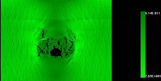
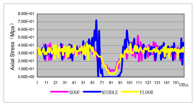
Figure 2. Diagrams of primary stress, acoustic emission and abutment pressure when 1.6 m bolt was used.
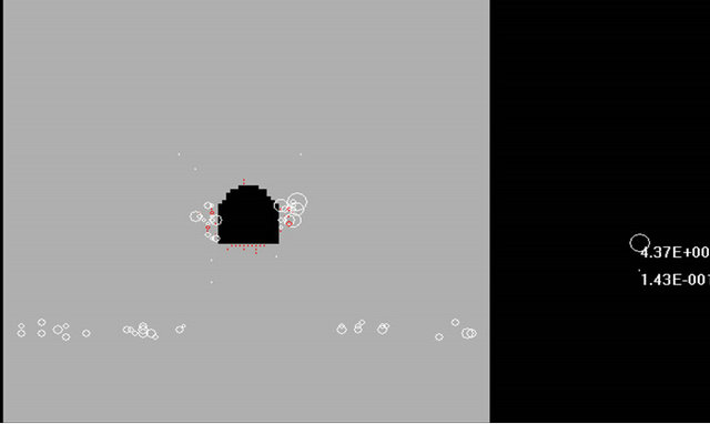
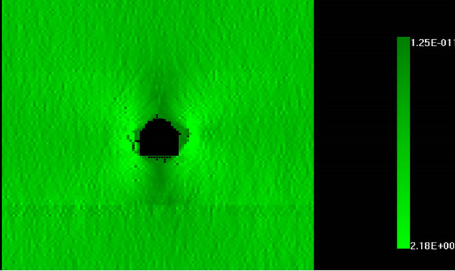

Figure 3. Diagrams of primary stress, acoustic emission and abutment pressure when 2.5 m bolt was used.
loose circle is small. Failure part is at the bottom, so reinforce the floor rock is important.
Grouting reinforcement technique is used, and grouting thickness makes 1.0 m. We simulate the failure process of the surrounding rock by increasing its strength within the scope of the grouting method. From Figure 4, we can know that: When the strength of the rock reaches 90 Mpa, the tunnel presents a stable state.
6. Conclusion
Based on crustal stress test analysis, this paper concludes that: the main transportation tunnel is exposed to an interphase hard and soft disadvantageous structure state and complex high stress repeated addition area; the horizontal tectonic stress is 3.3 times of the vertical stress; the width of the tunnel should be increased when it’s designed; the damage is mainly caused by the tectonic stress occurs in the roof and the floor, and the damage transfers to two ribs after the stress shifts. The simulation
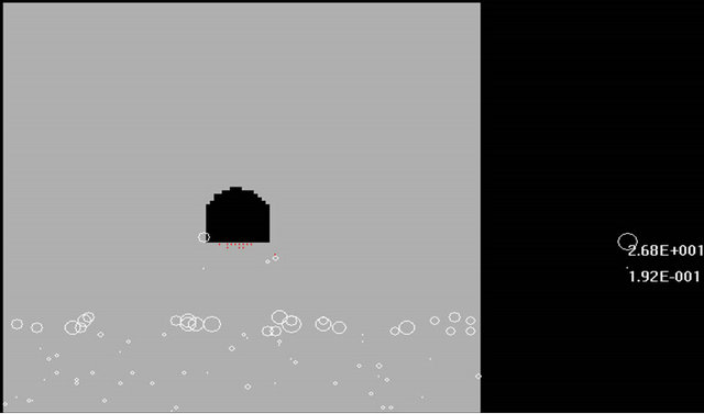
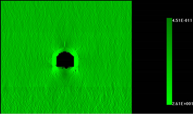

Figure 4. Diagrams of primary stress, acoustic emission and abutment pressure when 2.5 m anchor with 1.0 m grouting strengthening were used.
results show that: the damage of the transportation tunnel in level 14 mainly occurs in the floor and the two ribs; the failure process is spreading from the floor to the two ribs; the effect is obvious after using 2.5 m anchor with 1.0 m grouting strengthening.
7. Acknowledgements
This work is financially supported by National Basic Research Program (973) of China under Grant No.2011- CB201204 and financially supported by the Fundamental Research Funds for Central Universities (No. 2011YZ06 and No. 2009QZ01).
REFERENCES
- S. J. Sun, L. Wang, D.-F. Zhang and H.-P. Wang, “TimeHistory Response Analysis of Surrounding Rock Mass in Process of Excavating Deep Tunnel,” Journal of China Coal Society, Vol. 36, No. 5, 2011, pp. 738-746.
- A. Ghosh and J. K. Daemen, “Fractal Characteristics of Rock Discontinuities,” Engineering Geology, Vol. 34, No. 1-2, 1993, pp. 1-9. doi:10.1016/0013-7952(93)90039-F
- E. Maranini and M. Brignoli, “Creep Behavior of a Weak Rock: Experimental Characterization,” International Journal of Rock Mechanics and Mining Sciences, Vol. 36, No. 1, 1999, pp. 127-138. doi:10.1016/S0148-9062(98)00171-5
- D. F. Malan, “Simulation of the Time-Dependent Behavior of Excavations in Hard Rock,” Rock Mechanics and Rock Engineering, Vol. 35, No. 4, 2002, pp. 225-254. doi:10.1007/s00603-002-0026-0