Journal of Signal and Information Processing
Vol. 3 No. 1 (2012) , Article ID: 17615 , 4 pages DOI:10.4236/jsip.2012.31003
Non-Statistical Multi-Beamformer
![]()
1Electrical Engineering and Computer Science Department, Texas A&M University-Kingsville, Kingsville, USA; 2Electrical Engineering and Computer Science Department, Syracuse University, Syracuse, USA.
Email: nuri.yilmazer@tamuk.edu, {wchoi01, tksarkar}@syr.edu, sunmeelbhumkar@gmail.com
Received November 3rd, 2011; revised December 25th, 2011; accepted January 10th, 2012
Keywords: Beamforming; Multiple Beamforming; Direct Data Domain Approach; D3LS; Efficient Beamforming; Single Snapshot
ABSTRACT
In this paper, a multiple beamforming technique is presented by using a direct data domain least squares (D3LS) approach. Direct data domain approach is very suitable for real time applications since it utilizes only a single snapshot of data as opposed to statistical approaches where multiple measurements have to be taken and the covariance matrix has to be formed. It is also very effective especially in the case of blinking jammers where the statistical approaches will fail or needs to perform additional tasks to overcome it. It has been previously shown that the D3LS can successfully handle only one or two Signal of Interests (SOI). Here, we have developed a new technique where multiple SOI can be handled simultaneously. Numerical simulations have shown that the new approach can maximize the signals from the direction of the SOI at the same time minimizing the jammers. The new approach can be successfully applied in the satellite communications, Over the Horizon Radars (OTHR) as well as wireless communications to detect or track multiple targets simultaneously.
1. Introduction
Adaptive array signal processing has been successfully used in radar applications over the years and is now being used in wireless mobile communications as well as in other emerging technologies. The advantage of the adaptive antenna array systems is that the Signal to Interference Ratio (SINR) of the received signal is increased and leads to a better estimation performance by maximizing the signals from the direction of SOI while placing deep pattern nulls along the direction of the interference. This is achieved by manipulating the output of the antenna array elements by using some advanced signal processing techniques known as beamforming. Simply saying, the output of the antenna array elements are multiplied with some complex weights which will change the magnitude and the phase of the received signals leading to the formation of a specific antenna radiation pattern. By changing these complex weights the shape and the directivity of the antenna radiation pattern is adjusted. This method creates a radiation pattern where the signals phases are added in the direction of SOI and by nulling the pattern in the unwanted direction such as interferers. The radiation pattern can be adaptively steered in any direction by employing signal processing techniques instead of manually rotating the antennas as happened earlier radar systems. In order to track targets efficiently with antennas arrays, the complex antenna weights has be updated accordingly. The optimum value of complex weights has to be determined in a timely manner especially for real time applications. There are several techniques has been proposed for beamforming namely the statistical and nonstatistical approaches. Adaptive beamforming provides maximum directivity in the direction of the signal of interest while simultaneously placing nulls in the direction of the jammer signals. There are many algorithms exist in the literature for beamforming [1-8]. The statistical approaches rely on the collection of multiple samples during the operation to form a covariance matrix. In covariance based methods, the targets have to remain constant during the data collection, so it is not very suitable for highly dynamic environments and it will face extra challenges if there are blinking jammers as well.
To overcome these issues faced by statistical approaches, D3LS has been proposed by Sarkar [9] which is very suitable for real time applications. Additionally, D3LS is computationally efficient as compared to statistical methods since it premises on a single snapshot of data. Due to the nature of the problem, the computations are complex valued including the operations to find the optimal values of the complex weights. Finding these optimal weights requires the inversion of an ill-conditioned matrix so conjugate gradient method is utilized to calculate the inverse of such matrix. In order to reduce the computational complexity of the D3LS, a new approach leading to real valued antenna weights for adaptive beamforming has been proposed [10].
The D3LS adaptive beamforming techniques were developed for cases where there is only one signal of interest. But in most practical applications, there will be multiple targets or signals. To address this issue, Choi and Sarkar have proposed a new D3LS approach for the case where there are two signals of interest with multiple jammers [11]. In this paper, we have extended D3LS approach for three SOI case and this framework can also be extended for multiple signals of interest.
The rest of the paper is organized as follows; Section 2 explains the problem formulation for two SOIs case using D3LS approach, Section 3 provides the theory and the formulation for three signals case. Next, the simulation results are provided to show the efficacy of the method. Conclusion is given in Section 4 followed by the references.
2. Multiple Beamforming Using D3LS Approach for Three Signals
The D3LS approach for single SOI and two SOI cases have been explained in detail in [10]. Here, we extend the method for multiple SOI case. The direct data domain least squares approach for multiple beamforming problem is depicted in Figure 1 [11].
The antenna array consists of N antenna elements evenly separated by a distance of ∆ = λ/2, where λ is the wavelength of the signal of interest (SOI). The SOI expected voltage at each antenna elements is given by
 (1)
(1)
where n shows the index of antenna elements and ,
,  and
and  indicates the a-priori known DOA of SOI.
The voltage received at the antenna elements is given by,
 (2)
(2)
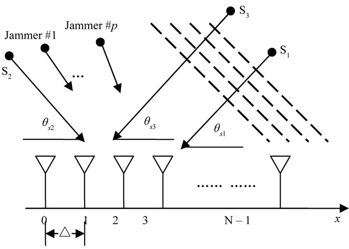
Figure 1. Linear antenna array, three SOI.
where, n = 0, 1, …, N – 1, and a1, a2 and a3 denote the complex amplitudes of the SOI, Aq denotes the complex amplitude of the qth interferer,  denotes the direction of arrival of the qth interferer, Bn denotes the clutter induced at the nth element and Tn represents the thermal noise induced at the nth antenna element.
The time difference between the neighbouring antenna elements caused by each signal can be defined as
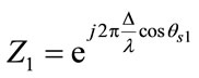 (3)
(3)
 (4)
(4)
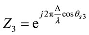 (5)
(5)
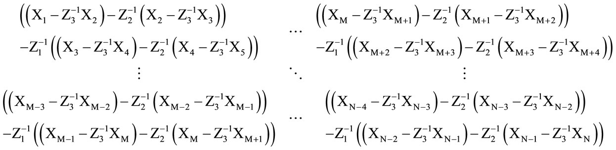
Then, the reduced rank matrix for the undesired noise matrix can be defined as Equation (6).
 (6)
(6)
If we consider the first term in the matrix above; the terms; ,
, 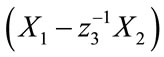 ,
,  and
and
 correspond to the noise, SOI 1 and SOI 2 between the antenna elements 0 - 1; 1 - 2; 2 - 3 and 3 - 4 as the SOI 3 component is removed after using
 . Additionally, after using
  the SOI 2 component is also removed from the terms
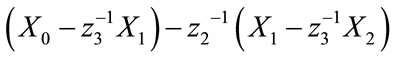 .
.
and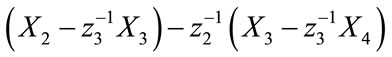 .
.
Eventually, after using  the SOI 1 component is removed and the whole term yields only noise information (undesired signals).
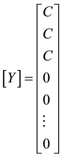
The SOI component of the adaptive array processing can be restored by defining the gain of the array (C = 1) that is formed by the weighted sum of the received antenna measurements
 (7)
(7)
Assuming the gain of this sub-array is equal to a value of  in the direction of SOI which is
 ,
,  and
and , this fact gives an additional equation yielding which is as shown in Equation (6). The F matrix formed is as shown in Equation (8) which contains signals and noise terms.
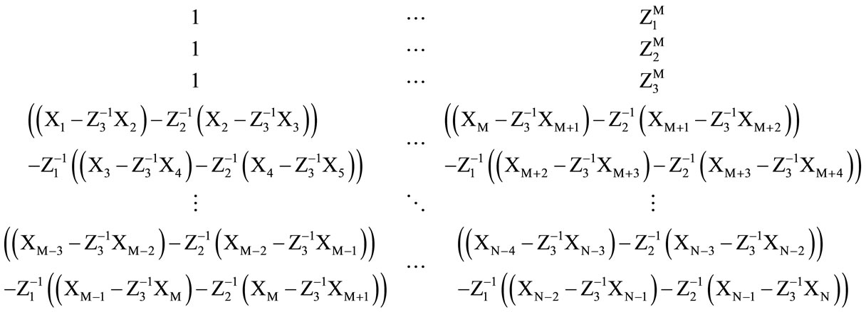 (8)
(8)
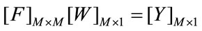 (9)
(9)
where,
The solution for the Equation (9) is obtained by utilizing the conjugate gradient method which yields the optimum values of the complex array weights. This formulation can be extended for multiple SOI case in the same way.
As the F matrix formed in Equation (9), first three rows of the matrix corresponds to the SOIs and the rest of the rows contain noise signals. Our goal is to find the complex antenna weights, matrix W. The solution requires the inversion of the matrix F and this matrix has very high condition number, an ill-conditioned matrix. The conjugate gradient method is utilized to find the inverse of the matrix. The solution yields the optimum values of the complex weights where it will lead to anantenna radiation pattern where maximum directivity is in the direction of SOIs and the nulls will be in the direction of the jammers. Due to the arrangement of the antenna elements and the formulation, this approach is named as Forward method. The problem can be reformulated by rearranging the antennas and the F matrix, the result is known as Backward method. The studies and simulation results have shown that two method’s performance is the same. In D3LS approach, the degrees of freedom is reduced to half where the number of signals can be detected and nulled is limited by the half of the number of array elements. By incorporating Forward and Backward method together, known as Forward-Backward method, degrees of freedom can be enhanced [9].
3. Simulation Results
In the simulations, we have considered 19 antenna elements with array element spacing of half a wavelength from each other. Signal to Noise ratio is set for each antenna element to 20 dB. The parameters of the SOI and interference are given below in Table 1.
As it can be seen from Figure 2, D3LS easily extracts the SOIs from 50˚ and 90˚, and nulls the jammers coming from 10˚ and 70˚ respectively. The jammers signals are nulled successfully and also the maximum directivity is obtained in the direction of SOI, which is 0 dB.
The parameters of the three SOI and interference for the simulation are given below in Table 2.
As it can be seen in Figure 3, D3LS approach successfully extract the SOIs at the correct angles (coming from 30˚, 70˚ and 130˚) and nulls the jammers simultaneously which are coming from 50˚, 100˚ and 150˚ respectively.
4. Conclusion
A new technique for multiple beamforming is proposed by using D3LS approach which premises on the single snapshot of data. The simulation results prove that the proposed technique maximizes the signals in the direction
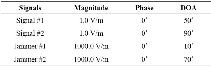
Table 1. Parameters for the SOI and interference.

Table 2. Parameters for the SOI and interference.

Figure 2. Beam patterns for two signals of interest and two jammers.
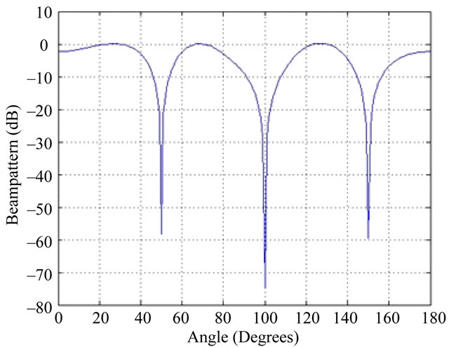
Figure 3. Beampattern for three signals of interest and three jammers.
of the signal of interest while simultaneously nulling the jammers. The new approach can be successfully applied in the satellite communications, Over the Horizon Radars (OTHR) as well as wireless communications to detect or track multiple targets simultaneously.
REFERENCES
- M. Chryssomallis, “Smart Antennas,” IEEE Antennas and Propagation Magazine, Vol. 42, No. 3, 2000, pp. 129- 136. doi:10.1109/74.848965
- R. Schreiber, “Implementation of Adaptive Array Algorithms,” IEEE Transactions on Acoustics, Speech and Signal Processing, Vol. 342, No. 5, 1986, pp. 1038-1045. doi:10.1109/TASSP.1986.1164943
- I. Chiba, W. Chujo and M. Fujise, “Beamspace Constant Modulus Algorithm Adaptive Array Antennas,” Proceedings of the IEEE 8th International Conference on Antennas and Propagation, Edinburgh, 1993, pp. 975- 978.
- S. Choi and T. Sarkar, “Adaptive Antenna Array Utilizing the Conjugate Gradient Method for Multipath Mobile Communications,” Signal Processing, Vol. 29, No. 3, 1992, pp. 319-333. doi:10.1016/0165-1684(92)90090-J
- A. El Zooghby, C. G. Christodoulou and M. Georgiopoulos, “Neural Network Based Adaptive Beamforming for One and Two Dimensional Antenna Arrays,” IEEE Transactions on Antennas and Propagation, Vol. 46, No. 12, 1998, pp. 1891-1893.
- S. Das, “Smart Antenna Design for Wireless Communication Using Adaptive Beam-Forming Approach,” TENCON 2008 IEEE Region Conference, Hyderabad, 19-21 November 2008, pp. 1-5.
- B. Widrow and S. L. D. Stearns, “Adaptive Signal Processing,” Pearson Education Asia, Second Indian Reprint, 2002.
- B. D. Van and K. M. Buckley, “Beamforming: A Versatile Approach to Spatial Filtering,” IEEE ASSP Magazine, Vol. 5, No. 2, 1988, pp. 4-24. doi:10.1109/53.665
- T. K. Sarkar, S. Park, J. Koh and R. A. Schneible, “A Deterministic Least Squares Approach to Adaptive Antennas,” Digital Signal Processing—A Review Journal, Vol. 6, 1996, pp. 185-194.
- W. Choi, T. K. Sarkar, H. Wang and E. L. Mokole, “Adaptive Processing Using Real Weights Based on a Direct Data Domain Least Squares Approach,” IEEE Transactions on Antennas and Propagation, Vol. 54, No. 1, 2006, pp. 182-191. doi:10.1109/TAP.2005.859753
- W. Choi and T. K. Sarkar, “Multiple Beamforming Technique Using Direct Data Domain Least Squares (D3LS) Approach,” IEEE Antennas and Propagation Society International Symposium, Albuquerque, 9-14 July 2006, pp. 3315-3318. doi:10.1109/APS.2006.1711322