Open Journal of Modelling and Simulation
Vol.02 No.04(2014), Article ID:50996,5 pages
10.4236/ojmsi.2014.24015
Design and Movement Simulation to the Cam of the Testing Device for Capacitor Encapsulation Equipment
Hongwei Fang, Guoquan Zhang, Jiaqing Jian
Machine Engineering Department, Wuhan Polytechnic University, Wuhan, China
Email: fanghw90@163.com.cn, gquanzhang@yahoo.com.cn, 1565430761@qq.com
Copyright © 2014 by authors and Scientific Research Publishing Inc.
This work is licensed under the Creative Commons Attribution International License (CC BY).
http://creativecommons.org/licenses/by/4.0/


Received 23 July 2014; revised 26 August 2014; accepted 18 September 2014
ABSTRACT
In this paper, in order to design a cam mechanism be up to the mustard, a set of methods are put forward that using the Visual Basic programming language based on solidworks to draw cam contour line and then get its 3D models and generate the cam motion simulation by the solidworks motion. In the end, it’s proved that the cam designed though this method met the requirement.
Keywords:
Visual Basic programming language, cam contour line, motion simulation

1. Introduction
In various fields, especially the automaton and automatic control device, various forms of cam mechanism are widely used. Compared with all kinds of pneumatic components, cam mechanism has a lot of advantages such as simple structure, low space utilization rate.
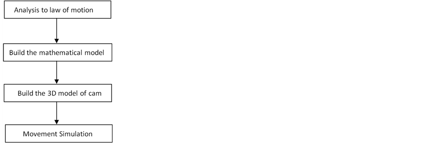
The point to design the cam is to get the right cam contour line what determines the operation of the came mechanism can achieve predetermined motion requirements [1] . Design method mainly has the graphic method and analytic method. The graphic method’s error is large and it’s difficult to the coordinates the point on the CAM contour line of accurate location, and can’t meet the requirements of CAM for accuracy. To the high speed cam, a set of methods were put forward that use the Visual Basic programming language based on solidworks draw cam’s contour line and then get its 3D models and generate the cam motion simulation by the solidworks motion. The whole process of designing the CAM can be summarized as follows.
2. Analysis to law of motion for the upward movement cam
2.1. Rising mechanism of the detection device for capacitor encapsulation equipment
As shown in figure 1 is the kinematic sketch of the rising mechanism to testing device for capacitor encap- sulation equipment. The agency system is made up of cam mechanism and linkage mechanism whose purpose is to realize the slider 5 reciprocating movement up and down. In the figure, the cam 1 is fixed on the transmi- ssion shaft and the roller 2 is on the rocker 3 which is fixed on the rack. As the original dynamic mechanism, the cam 1 drives the swinging rod 3 reciprocating swing. Then the connecting rod 4 which is articulated on swing- ing rod 3 drives the slider reciprocating movement up and down. Finally, the capacitor is detected by the detection device.
2.2. Analysis of the law of motion to the slider
In order to guarantee the stability and efficiency of the encapsulation equipment. The sliding block motion must be in harmony with the other parts’ motion lawand maintain the consistency of scheduling. Combined with the enterprise in the actual production experience and requirements, the motion law of the slider is put forward the following requirements:
1) Actuating travel is quick and steady.
Starting speed of the slder is required to be fast in the process of rising in order to ensure the production efficiency of the whole equipment. But considering the stability of detection device, in the second half of the process the speed of the slider should be reduced gradually to guarantee the impact is lowet when it reaches the highest position.
2) Time of far reposing state is long enouth.
The silder should stop for a period of time on the highest position to let the manipulator move the capicitor to the checking station.
3) Impact of return stroking state can’t be too strong.
In order to make the capacitor fixed on the workstation, the slider should slide down quickly. But due to the capacitor’s shell is weak and can not be beared too big impact, the speed of the slider should be as low as possible when it reached the lowest position.
4) According to the requirements of enterprise and the dimension of capacitor, it is regulated that the strokemm of the slider is 12 mm, and the movement cycle of cam is 1 s.
According to the movement temporal relations of different parts, the motion law of the cam is regulated as follows in table 1.
3. Build the mathematical model of cam mechanism
According to the principle of reversal method, it’s set that the  as the radius of the cam and the push rod will move distance
  when the cam rotate the angle
 . So the rectangular coordinate parameter equation of the cam profile is achieved as follows [2] :
 (1)
(1)

Figure 1. the kinematic sketch of the the cam of the testing device for capaci- tor encapsulation equipment. 1—cam; 2—roller; 3—swing road; 4—connect- ing rod; 5—slider.

Table 1. the angle of the cam to state of motion.
According the Formula (1) and the motion law of push rod, the cam theory profile can be concluded.
When , the push rod ries by uniform accelerated motion. The rectangular coordinate parameter
equation of the cam profile is achieved as follows:
 (2)
(2)
When , the push rod rises by uniform retarded motion. The rectangular coordinate parameter
equation of the cam profile is achieved as follows:
 (3)
(3)
When , the push rod stops on the highest station. The rectangular coordinate parameter
equation of the cam profile is achieved as follows:
 (4)
(4)
When , the push rod falles by uniform accelerated motion. The rectangular coordinate
parameter equation of the cam profile is achieved as follows:
 (5)
(5)
When , the push rod falles by uniform retarded motion. The rectangular coordinate
parameter equation of the cam profile is achieved as follows:
 (6)
(6)
When , the push rod stops on the highest station. The rectangular coordinate parameter
equation of the cam profile is achieved as follows:
 (7)
(7)
4. Build the 3D model of cam
4.1. Write the programs of contour line
Open the VB programming interface and write the programs of different motion laws. Due to the limitation of space, the program can’t be listed [3] -[7] .
4.2. CAM entity model Is set up
After writing the cam contour line program and running the program, a coordinate point TXT file was got. Then import it into solidworks and generating theory of cam outline curve. Then using the command [isometric entity] in the sketch, input 11 mm roller radius, get the job cam contour curve. Finally, cam entity model is established by [drawing] and [punching] command [8] -[11] . As shown in figure 2.
5. Based on Solidworks Motion movement simulation
5.1. The purpose of using Solidworks Motion movement simulation
In the design of precede, we have been using Adams to analyse movement simulation of mechanism. Due to many institutions are modeled in solidworks, so by solidworks turned Adams process is more trouble. In the CAM design, we try to use solidworks motion plug-in of solidworks simulation of CAM mechanism, thus not only can finish for the realization of the CAM mechanism Motion simulation, also reduce the file input process involved in different software, greatly improve the design efficiency and convenience.
5.2. Process and result of motion simulation
Enter the solidworks motion interface and give the cam a rotary motor whose revolving speed is 60 r/min. After the motion process is over, the motion curve about displacement to time and the motion curve about speed to time can be achieved as follows in figure 3 and figure 4.
According to the curves, it’s showed that the slider starts to rise by uniform retarded motion and then rises by uniform retarded motion in the actuating travel. In the return stroking state, the slider starts to fall by uniform retarded motion and then falls by uniform retarded motion. In the far reposing state and near reposing state, the slider stops for a certain time. In conclusion, the cam is designed meets the requirement.

Figure 2. cam three-dimensional entity model.

Figure 3. the displacement to time curve.

Figure 4. the speed to time curve.
6. Conclusion
In this paper, in order to design a cam mechanism be up to the mustard, a set of methods were put forward that using the Visual Basic programming language based on solidworks draw cam’s contour line and then got its 3D models and generated the cam motion simulation by the solidworks motion. This method can improve the efficiency and accuracy and has a good effect on the enterprise.
References
- Guo, L.F. and Guo, S.S. (2005) The Design of CAM Contour and Simulation. Mechanical Research and Application, 19, 95-97.
- Heng, S. and Chen, Z.M. (2006) Theory of Machines and Mechanisms. Higher Education Press, Beijing, 151-168.
- Chen, H.S. (1999) Visual Basic Programming Tutorial. Suzhou University Press, Suzhou.
- Zhang, Q.L. (2005) Direct Computer Aided Design of Disk CAM Mechanism with Push Rod Past. Changsha Aviation Occupation Technical College Journals.
- Wang, D. and Li, C. (2003) Self-Adaptive Dynamic Matrix Control for High-Speed Machining Servo Control. International Journal of Advanced Manufacturing Technology, 10-11.
- Jaganathan, A. and Lin, Y.J. (2013) Accurate Machining of Freeform Surfaces by Restraining Cutter Contouring Errors. International Journal of Advanced Manufacturing Technology, 9.
- Muftik, A.L. and Khan, A.S. (2012) Performance Evaluation of Yanmar Paddy Transplanter in Pakistan. Agricultural Mechanization in Asia.
- Ying, Y.B. and Zhao, Y. (1997) Research in Dynamic Simulation of Sparating-Pianting Mechanism of Rice Transplanter. Agricultural Mechanization in Asia.
- Solidworks Corporation (2004) Solidworks 2004 User Guide.
- Myung, S. and Han, S. (2011) Knowledge-Based Parametric Design of Mechanical Products Based on Configuration Design Method.
- Lin, B.-T. and Kuo, C.-C. (2011) Application of an Integrated CAD/CAE/CAM System for Stamping Dies for Automobiles. The International Journal of Advanced Manufacturing Technology, 9-10.