Open Journal of Fluid Dynamics
Vol.06 No.03(2016), Article ID:70541,16 pages
10.4236/ojfd.2016.63014
Momentum Transfer on Underwater Shock Generation Induced by Pulsed Laser Irradiation with Thin Metal
Rokhsan Ara Hemel1, Hiroyuki Hirahara2, Kento Takahashi1
1Graduate School of Science and Engineering, Saitama University, Saitama, Japan
2Faculty of Engineering, Saitama University, Saitama, Japan

Copyright © 2016 by authors and Scientific Research Publishing Inc.
This work is licensed under the Creative Commons Attribution International License (CC BY 4.0).
http://creativecommons.org/licenses/by/4.0/


Received: August 4, 2016; Accepted: September 10, 2016; Published: September 13, 2016
ABSTRACT
The present paper has investigated the momentum transport phenomena of underwater shock wave generation in terms of photo-acoustic wave with a very thin metal. The shock wave was induced by a pulsed-laser irradiation. In order to clarify the momentum transport mechanics in this phenomenon, we have been considered the momentum and energy transport from laser to metal, and metal to water. A numerical solution of thermo-elastic wave in metal has been obtained to estimate a fundamental gain of the longitudinal wave. Then, the underwater shock wave phenomena have been analyzed by adapting compressible fluid dynamics with suitable boundary condition between the solid and liquid. We had performed an experiment as well and observed the shock wave with optical system. The aim of the research is to estimate the underwater shock wave strength theoretically. The metal region was calculated by Laplace transformation of heat conduction and wave equations. The water region was simulated by MacCormack’s method. Some of boundary conditions have been examined and the acceleration condition has been adopted at the interface. The simulated results show a good agreement with experimental result, consequently the momentum transfer mechanism from longitudinal wave to underwater shock wave has been cleared in the present report.
Keywords:
Underwater Shock Wave, Momentum Transfer, Longitudinal Wave

1. Introduction
It is an important technique to provide a concentrated high energy into a small region in a various field, e.g., bio-engineering, applied science and medical science. Laser irradiation is one of the powerful candidates for supplying such high energy in short time. Generally speaking, there are variety of laser processing work depending on laser power such as welding, drilling, melting etc. During those processes, shock waves frequently are generated by laser irradiation. Then, the laser induced shock waves have been studied intensively in a wide field such as material processing, micro- and nano-technology, bio-engineering and medical science [1] - [3] . The dynamics of laser induced shock has been studied experimentally, theoretically and numerically aimed to examine the velocity, density, pressure rise around the shock wave for a specific application. Various methods also have been applied to measure the pressure change due to the shock wave propagation by using hydrophones or piezoelectric transducers [4] , fast photography and interferometry [5] , in experimentally. In general, pressure sensors are used to measure shock pressure up to several hundred bars based on piezoelectric properties. Because the shock wave has non-equilibrium process in very short time, the measurement is difficult with good accuracy in time and space resolution. In addition, the momentum and energy transfer dynamics is too complicated to follow up the phenomena. Furthermore, a modeling of its transport phenomena is required to be completed in numerical simulation.
In the present research, opto-physical interaction wave and shock wave excited by the interaction between laser light and metal has been discussed in the case of relatively low laser irradiation intensity. When laser light interacts with metal, rapid thermal process produces prompt movement in the structural component of the metal surface, consequently, causing the strengthening of vibration. In general, during the interaction of a laser pulse with the solid metal surface, the metal surface usually gains the momentum and energy. After the light impaction, various types of thermo-elastic waves launched from the illuminated surface towards the bulk of the solid objects. At this moment, a longitudinal wave propagates through the metal with a sharp peak intensity and velocity compared with the other waves e.g., shear waves, Rayleigh waves, head waves etc. and thereafter, the shear wave propagates through the solid with approximately half of the velocity of the longitudinal wave [6] . Various investigations have done regarding the thermo-elastic wave generation and propagation through the solid induced by pulsed laser, where the solutions of the wave have obtained by analytical method [7] [8] . Among these thermo-elastic waves, longitudinal wave with high intensity carries and redistributes the acquired momentum through the object while it propagates.
In our investigation, the momentum transfer from longitudinal wave to underwater shock wave has been discussed in detail. The longitudinal wave transports the momentum and energy through the metal to water, consequently, a shock wave propagates into water. To understand this principle, we had carried out the experiment on these phenomena and also investigated the longitudinal wave behavior into metal by analyzing metallic response induced by pulsed laser with the help of governing equations of heat transfer and displacement due to laser heat energy. In the experiment, the underwater shock wave was generated with a shock driver specified by a flat glass of which terminal surface coated with thin titanium (Ti) metal film and observed with optical system by shadowgraphic visualization. Finally, a numerical simulation has been conducted to confirm the transportation of momentum through the longitudinal wave from metal to water for shock wave generation by comparing the pressure jumps between experiment and theoretical prediction.
2. Experimental Procedure
Figure 1 illustrates the experimental diagram for underwater shock generation. A Q-switched pulsed Nd: YAG laser with wavelength 532 nm (New Wave; Solo-3) was used for underwater shock generation and its maximum output energy is 50 mJ/pulse and pulse duration 5 ns. The irradiation intensity on the metal target has been adjusted by power controller and the energy was measured by a laser power meter (Ophir, PE-25). To achieve the minimum irradiation area, the beam waist radius was calculated with a formula Gaussian beam waist [9] . In the experiment, the diameter of irradiation region, D was fixed as 3.0 mm and to avoid the metal abrasion, laser irradiation intensity (I0) was varied up to 320 GW/m2.
For shock wave visualization, shadowgraph technique was used in the experiment. Another Q-Switched pulsed Nd: YAG laser with 532 nm wavelength (Quantel; Ultra) was used for shock visualization. The maximum output energy is 30 mJ/pulse and pulse duration 5 ns. To capture the shadowgraph images, a CMOS camera (IDT, XS-5) with a micro zoom lens (Leica, Microsystem mod Z16) was also used. The camera resolution is 1280 × 1024 pixels and 10 bits in depth. A Timing controller (Lab Smith, LC880) was used to control the laser irradiation and visualization sequence. Therefore, the temporal front position of the shock wave was measured through the snap shots by the shadowgraph technique.
A water tank of size, 180 × 120 × 220 mm3 was used for underwater shock generation and the shock driver, flat glass coated with metal, was attached the water surface of the
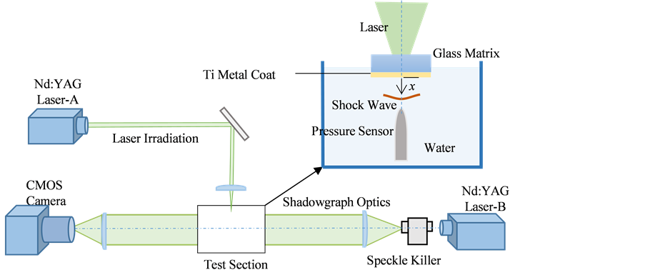
Figure 1. Schematics of experimental apparatus.
water tank. In our preliminary experiment, we had inspected the metal thickness for generating a shock wave effectively. It was found that it should be few hundred-nano- meter and also many researchers used few hundred thickness metal for shock generation [10] [11] . Therefore, the targeted metal coat is 100 nm thickness. The coating is done by the spattering on one side of the glass plate and the laser irradiated from the opposite of the coated surface of the glass. A PVDF (Polarized PolyVinylidene DiFlu- oride) pressure sensor (Imotec; 80-0.5-4.0) was used to measure the shock pressure, which was immersed in the tank just below the shock driver. This pressure sensor is sufficient sensitivity with less than 0.5 mm head diameter and also can record a pressure rise with 50 ns response for explosion wave in water up to 1 kbar.
3. Analytical Procedure in Metal
The physical process appeared in the present research is shown in Figure 2 schematically. The glass coated with metal is irradiated by laser from upper side (a). The irradiation induces photo-physical interaction on the metal, and consequently a wave is propagated in the metal (b). The waves induced by the photo-physical interaction can be classified into a few waves, such as Rayleigh, Lamb, and longitudinal waves based on the propagating direction for different boundary conditions [12] [13] .
Here, we will discuss the wave propagation perpendicular to the laser irradiation surface. Since the irradiation region size is sufficiently larger than the propagation distance, the wave is expected to be planer one, namely the wave becomes one-dimensional. We supposed the metal plate being isotropic and homogeneous for the laser irradiation. The governing equation for heat transfer and displacement due to laser heat energy are described with Equations (1) and (2), with initial and boundary conditions [14] [15] . A general solution of laser induced photo-acoustic wave in metal will be formulated using Laplace transformation procedure. The solution of the equation provides a very important understanding about the longitudinal wave property. The property of the underwater shock wave will be presumed by using these results.
 (a) (b)
Figure 2.Waves propagation in metal due to laser irradiation.
 (1)
(1)

In Equation (1), I(t) represents the laser intensity as follows [14] ,

where, T, ρ, cv, E are temperature, density, specific heat at constant volume, and laser energy per unit area respectively. R and β are the reflection ratio of laser light and the absorption coefficient of metal. Usually, it is regarded as the Gaussian profile and described with the Lambert-Beer’s law. The flat glass and metal contact surface position is x = x0 = −100 nm, as metal thickness is 100 nm which is shown in Figure 2. The boundary condition represents that the system follows adiabatic approximation at left end i.e. x = x0 and the temperature is ambient one at infinity. For the kinetic response inside of metal, we can represent the displacement with wave equation. For the displacement u, using density ρ, bulk and shear modulus B and G, and , with the volumetric thermal expansion coefficient βT, the governing equation is expressed with boundary condition as follows,
 (2)
(2)

Since the metal is coated on the flat glass, we can assume that u = 0 at x = x0. Also u = 0 at infinity because there is no thermal effect there. The Laplace transformation of the Equations (1) and (2) are obtained as follows,
 (3)
(3)
 (4)
(4)
Here  and
and . Consequently, the solution can be obtained from the inverse Laplace transformation, which was solved numerical procedure by using Matlab. In the analysis, we used the computational grid with dx = 1 nm, and time resolution dt = 1 ps.
4. Numerical Analysis for Underwater Shock Wave
4.1. Governing Equations
To solve the underwater shock wave problem, a set of continuum, momentum, and energy equations for compressible fluid without heat source has been solved with finite differential method. The governing equation are expressed in conservative form as follows [16] - [18] ,

where U, E and R in x-direction, are described as follows,

Here ρ is the density of water, P is the pressure,  is the momentum, u is the velocity component in x-direction,
  is the specific internal energy of water,
  the specific heat at constant volume, T the temperature, and
  where
where  is the viscosity. The In order to take compressibility of water into consideration, the modified Tait equation of state was applied in the present calculation. It is given by as follows [19] [20] ,

where, the constant B = 304 MPa, γ = 7.15. P0 and ρ0 are atmospheric pressure and reference density, respectively.
4.2. Numerical Scheme
In order to solve the one-dimensional Navier-Stokes equations with modified Tait equation of state numerically, MacCormack’s scheme has been applied to the compressible water dynamics in the present study. This method is well known classical scheme and has two steps iteration such as predictor and corrector steps [18] .
The method has second order accuracy as using forward difference at predictor step and backward difference at corrector step for space derivative. The characteristics of this scheme had been well inspected in early time of numerical simulation development, so we used this old scheme in order to check the fundamental features of expression about underwater shock wave without any treatment like MUSCLE or TVD schemes, etc. The time resolution was 1 ps as well as the solid analysis, therefor, the grid size was determined by CFL condition by using water sound speed and the time increment.
4.3. Boundary Condition
Now, let’s consider the boundary condition between the metal and the water. Initially, metal gains the momentum after laser irradiation, and this momentum has been carried by the longitudinal wave accompanying with drastic value change through the metal. Since water top surface (x = 0) is contacted with the metal terminal surface, so the longitudinal wave causes the pressure jump in water and it propagates as a shock wave. Figure 3 illustrates the basic principle of momentum transportation.
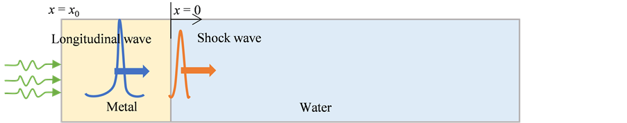
Figure 3. Schematic illustration showing underwater shock wave generation.
Let’s take one-dimensional coordinate in semi-infinite (x > 0) water section. The momentum impacted at x = 0 by the longitudinal wave propagation through metal thin film will transfer to water, then it generates a shock wave, as shown in Figure 3. In this study, we will determine the suitable boundary condition by analyzing the opto-acoustic wave properties into the metal as a primary shock-driving source.
As the practical boundary condition in simulation, we can assume some physical condition to produce shock wave, such as piston driving, hammering, or pressure driving. For piston driving, the interface displacement, namely, the velocity should be estimated. On assuming a hammering effect, an acceleration might be considered. As the pressure condition, the stress propagation should be taken into account. In the following section, we will discuss which condition is suitable for shock generation.
5. Result and Discussion
5.1. Experimental Result
The experiment was carried out as described above in section 2. The shock driver, flat glass coated with metal was attached the water surface of water tank for underwater shock wave generation. There are several optical methods to visualize the shock wave e.g., shadowgraph method [21] [22] , schlieren method [23] and holographic interferometry. In the present research, the shock wave propagation was visualized by shadowgraph technique. In the experiment, the shock wave pressure was measured by a pressure sensor (PVDF), to measure the shock wave strength, pressure sensor was immersed in water and retreated according to the shock capturing position.
The underwater shock images at I0 = 80 GW/m2 are shown in Figure 4. The dimension of observation region is 10 mm. The photo images show the shock wave front emitted from the shock driver at different time after laser irradiation, just before coincidence with pressure sensor. The initial shape of the generated shock wave was planner and this shape was maintained up to several millimeter distance. However, at far distance from the shock driver, the shape becomes spherical, certainly, because of the self-similarity of shock propagation like spherical wave. The pressure rise will be discussed in section 5.3.
5.2. Longitudinal Wave Propagating in Metal
In this section, our interest is to find a most significant physical parameter of metal to determine the boundary condition for generating underwater shock wave. Therefore,
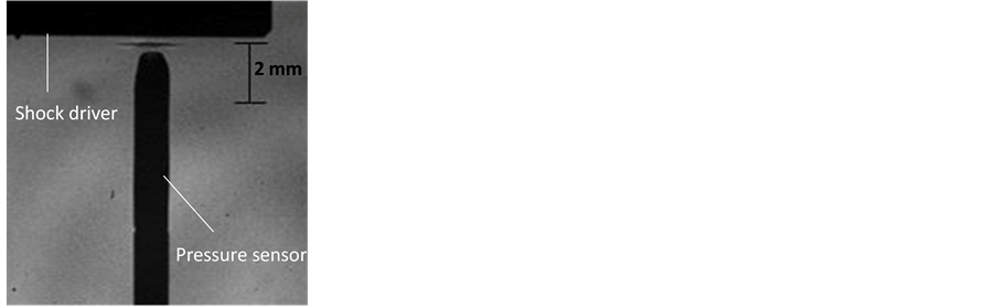
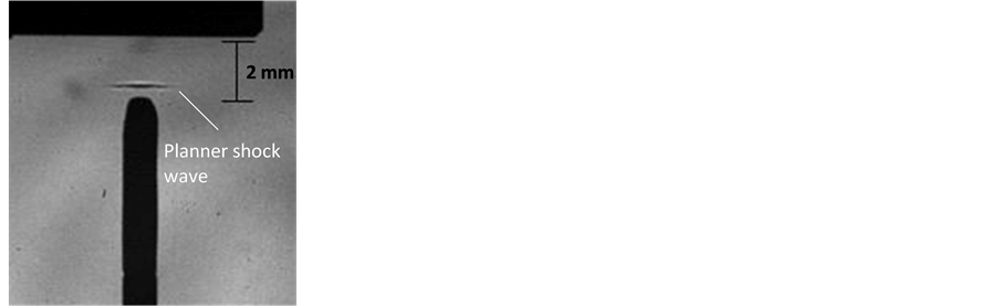 x = 269 µm; t = 0.15 µsx = 1654 µm; t = 1.1 µs
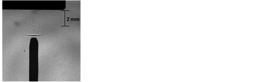
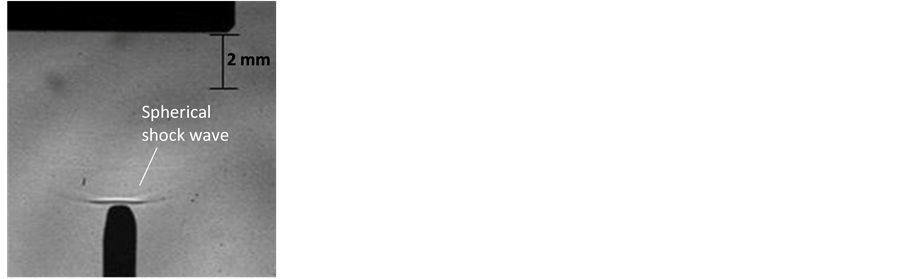 x = 3272 µm; t = 2.2 µsx = 5944 µm; t = 4 µs
Figure 4. Shock wave front position apart from the shock driver with shadowgraph technique.
calculation have been carried out to inspect the longitudinal wave behavior of the metal at the terminal surface such as displacement, velocity, acceleration etc. will be considered in the following section. The terminal surface of metal is at the position x = 100 nm, same as the experimental procedure. The calculations have been carried out using solution of the photo-acoustic wave, which is described in section 3. Here, the physical properties of Titanium metal are shown in Table 1.
Figure 5 shows the laser profile, in which the effective pulse duration is 5 ns. The calculation is done using 80 GW/m2 laser irradiation intensity, which is estimated with laser energy per pulse, irradiation spot area and duration time. Here, the laser energy per pulse and irradiation area have been measured with a power meter and an alignment paper respectively. Figure 6 represents the temperature response of the terminal surface of the metal. From the figure, temperature reaches at its peak vale within 10 ns and after that it starts to weaken. Temperature profile demonstrations prompt variation inside the metal.
Figure 7 shows the variation of displacement and velocity at x = 100 nm. The graph demonstrates that the displacement (u) and velocity (v) are very low and slow during entire time. As long as considering this duration time, we cannot identify any discontinuous change inside the metal. The displacement curve reaches its peak value within 10 ns and peak value is the order of 10−11 m. This sub-angstrom scale value cannot produce strong pressure in water. On the other hand, the time derivative of u gives the velocity v. As shown the velocity graph, the speed is order of 10−3 m/s and it touches its

Table 1. Table Physical properties of metal Ti.
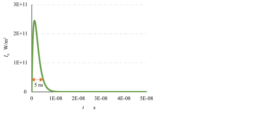
Figure 5. Laser profile.
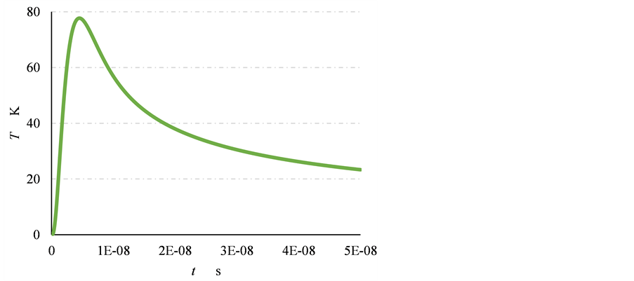
Figure 6. Temperature response at x = 100 nm.
peak at about 2 ns. As far we know, underwater shock wave generation by a piston motion, such small velocity cannot be the candidate to generate the discontinuity like shock wave. Therefore, we focus our interest at the different physical parameters of metal is acceleration, which calculated from the time derivative of v.
Figure 8 shows the strain and stress variation for 50. The strain curve reaches to the maximum of order of 10−3 at t = 10 ns, which represents the tensile strain. Moreover, negative strain is found within short time at the beginning. Therefore, strain curve characterizes that initially compressive strain propagates through the metal, then it turns to large tensile strain and it decreases slowly. The phenomena represent the thermo-elastic behavior of the metal due to laser heating. On the other hand, the internal stress profile represents the compressive stress propagation through the metal thin plate in 50 ns and after 5 ns, compressive stress reaches its peak value of order 106 approximately. The figure shows the monotone behavior, no discontinues found in the graph.
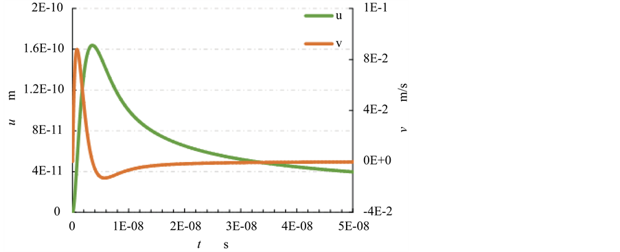
Figure 7. Displacement and velocity variation.
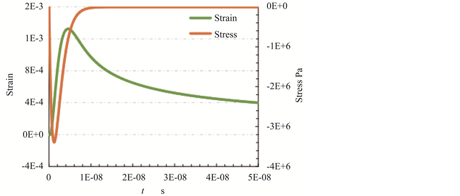
Figure 8. Strain and stress variation in 50 ns.
Figure 9 represents the acceleration variation in 50 ns at the terminal surface of metal. The acceleration profile is very interesting from the view point of candidate of boundary condition for underwater shock generation. The figure shows the spikes immediately after the laser irradiation. The calculation has been conducted in sufficient precision with 1 ps time increment, hence the spike is not derived by numerical error. From the figure, it also observed that acceleration curve reaches to its apex value in 20 ps of order 108, after reaching at this high peak value, the curve decrease rapidly in 800 ps and then drops its minimum value of order 108, thereafter it increases gradually again. Comparing with the earlier graph, it can be confirmed that this drastic variation of acceleration wave is very significant to produce the underwater shock wave.
Figure 10 gives the information regarding the acceleration variation in 800 ps for increasing laser intensity. In the calculation, the laser intensity was ranged from 0 to 200 GW/m2 with 40 GW/m2 interval, therefore 40, 80, 120, 160 and 200 GW/m2 has been used. The acceleration shows the rapid jump in 10ps and decreases linearly until 800 ps. The figure also indicates the acceleration wave with higher positive and negative spike is obtained with increasing laser intensity.
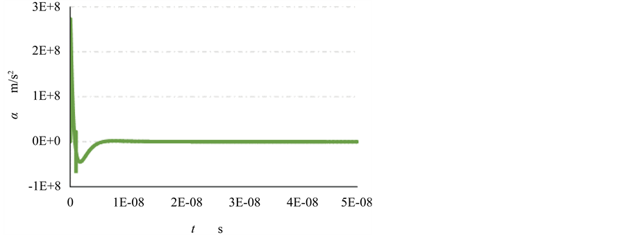
Figure 9. Acceleration at position 100 nm in 50 ns.
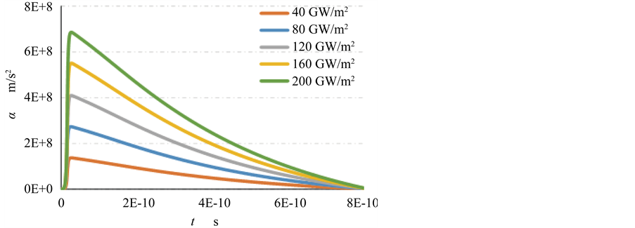
Figure 10. Acceleration after laser irradiation in 800 ps represents the longitudinal wave.
Therefore, Figure 9 and Figure 10 provide the evidence that acceleration wave characterizes the longitudinal wave, as it responses in very quick after laser irradiation, about 20 ps with high amplitude of order 108 m/s2. It can be concluded that a discontinuous acceleration wave which related to the force due to laser irradiation is propagating in metal and the wave carries the momentum and energy from the laser irradiation via metal into the water for shock generation. Indeed, this force should be used as a boundary condition in the underwater shock simulation as will be described in the next section.
5.3. Numerical Result in Water
Numerical calculation for underwater shock generation have been conducted using one-dimensional governing Navier-Stokes equations with modified Tait equation of state for water, as described in section 4. In the simulation, we have to select a suitable boundary condition to generate a shock wave. The shock wave will be formed due to a discontinuity of some physical property. For example, the shock tube calculation in air, high pressure region and low pressure region is separated by a diaphragm and after diaphragm broken shock wave propagated to the low pressure region. Next, a piston driving will produce a finite amplitude wave and the wave will develop to a shock wave due to non-linearity. Similarly, for underwater shock generation, it is necessary to find such discontinuity in the present phenomena. According to the analytical calculation in metal as in section 5.2, we concluded that laser induced force in longitudinal wave should be used as a boundary condition. It namely confirmed that the acceleration wave act as a front of longitudinal wave propagating through the thin metal and supplies the laser induced force to the water for shock generation. Therefore, boundary condition of water surface at x = 0, as shown in Figure 3, becomes as follows,

where subscripts, m and w stands for metal and water, ρ is the density and a is the acceleration. This relation represents the force balance per unit volume at the interface.
The computation domain for underwater shock simulation was 10 µm and the physical time duration was 7 ns. The calculation has been conducted with Matlab with sufficient accuracy by 1 ps time increment. Figure 11 illustrates the acceleration and the shock pressure in water at the interface, due to the longitudinal wave effect by laser irradiation. In this simulation, the laser intensity was supposed as 80 GW/m2. The magnitude of acceleration reaches its maximum of order 108 m/s2 just after laser irradiation and thereafter it attenuates within 800 ps. The calculated shock pressure was shown in this figure. Apparently, water pressure increased instantaneously to about 750 KPa at 800 ps and it propagates into the water.
Figure 12 show the shock wave propagation for four laser irradiation intensities as 80, 120, 160 and 200 GW/m2. Figure 12 represents the shock wave propagation at time 1, 3 and 5 ns. The pressure increases of course with laser irradiation intensity. Also in these curves, the rarefaction wave accompanies behind the shock wave. Consequently,
800 ps
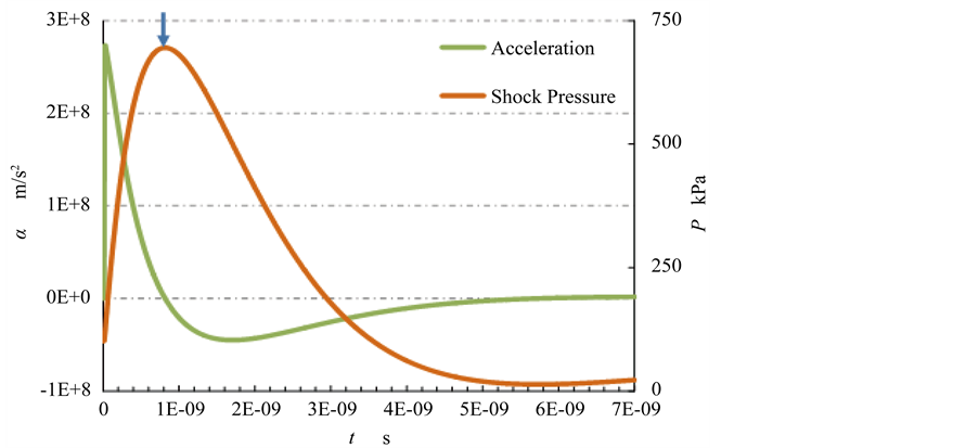
Figure 11. Shock generation in water due to the longitudinal wave effect.
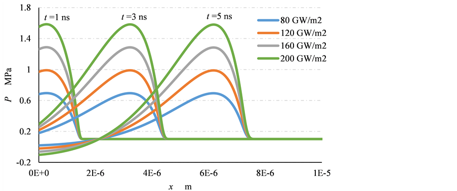
Figure 12. Laser induced shock wave propagation in water at different time.
the shock wave was formed in terms of the acceleration of metal and shock pressure increases during the positive duration of metal acceleration. Then the shock pressure decreases, i.e. a rarefaction wave follows the shock front.
Figure 13 represents the comparison of underwater shock pressure between the experimental results with uncertainty and numerical ones for different irradiation intensity of 40, 80, 120, 160, 200 GW/m2. The experimental result was obtained at the x = 4 mm, whereas the numerical results were acquired at x = 8 µm. The numerical results could not be calculated at the same position because we needed to use so fine grids that need more computational time for large time simulation. In the present comparison, those results show a good agreement in whole experimental conditions. Thus, it was proved that the present boundary condition was quite reasonable and the present modeling could be applicable to the underwater shock generation in opto-physical process.

Figure 13. Comparison of underwater shock pressure for different laser intensity.
Laser intensity dissipated for lower irradiation intensity in the experiment due to the position of the laser was far from test section. Thus, the experimental result for 40 GW/m2 deviated from the numerical result.
6. Conclusions
The present research confirmed the momentum transport effect for underwater shock wave generation carrying through the drastic variation of longitudinal wave into metal thin film due to the pulsed laser irradiation. We had performed the experiments and numerical analysis based on thermos-elastic mechanism. The acquired shock pressure in numerical results provides very consistent agreement with the experimental results.
The characterization of longitudinal wave is performed by considering the general solution of thermo-elastic wave with heat conduction equation. It was found that acceleration represents the longitudinal wave as the discontinuous phenomena, in which the prompt rise time to reach the maximum value is 20 ps in the present case, and the maximum value of order 108 m/s2. From this point of view, numerical calculation should be implemented in water region by considering the laser induced force as a boundary condition for underwater shock generation. Practically, e.g., the pressure rise in water obtained from numerical calculation was several hundred kPa with 800 ps pressure rise time for laser irradiation 80 GW/m2 and 5 ns laser duration.
Cite this paper
Hemel, R.A., Hirahara, H. and Takahashi, K. (2016) Mo- mentum Transfer on Underwater Shock Ge- neration Induced by Pulsed Laser Irradiation with Thin Metal. Open Journal of Fluid Dynamics, 6, 166-181. http://dx.doi.org/10.4236/ojfd.2016.63014
References
- 1. Rassweiler, J.J., Knoll, T., Kohrmann, K.U., McAteer, J.A., Lingemann, J.E., Cleveland, R.O. and Chaussy, C. (2011) Shock Wave Technology and Application: An Update. European Urology, 59, 784-796.
http://dx.doi.org/10.1016/j.eururo.2011.02.033 - 2. Tominaga, T., Nakagawa, A., Hirano, T., Sato, J., Kato, K., Hosseini, H.S.R. and Takayama, K. (2006) Application of Underwater Shock Wave and Laser-Induced Liquid Jet to Neurosurgery. Shock Waves, 15, 55-67.
http://dx.doi.org/10.1007/s00193-005-0005-y - 3. Menezes, V., Takayama, K., Ohki, T. and Gopalan, J. (2005) Laser-Ablation-Assisted Microparticle Acceleration for Drug Delivery. Applied Physics Letters, 87, 1-3.
http://dx.doi.org/10.1063/1.2093930 - 4. Park H.K., Kim, D., Grigoropoulos, C.P. and Tam, A.C. (1996) Pressure Generation and Measurement in the Rapid Vaporization of Water on a Pulsed-Laser-Heated Surface. Journal of Applied Physics, 80, 4072-4081.
http://dx.doi.org/10.1063/1.363370 - 5. Ward, B. and Emmony, D.C. (1991) Direct Observation of the Pressure Developed in a Liquid During Cavitation-Bubble Collapse. Applied Physics Letters, 59, 2228-2230.
http://dx.doi.org/10.1063/1.106078 - 6. Arrigoni, M., Hu, Q., Boustie, M., Berthe, L. and Monchalin, J. (2008) B-Scan Simulations with Abaqus for Laser Ultrasonic Inspection of Structures. 1st International Symposium on Laser Ultrasonics: Science, Technology and Applications, Montreal, 1-6.
- 7. Sanderson, T., Ume, C. and Jarzynski, J. (1998) Longitudinal Wave Generation in Laser Ultrasonics. Ultrasonics, 35, 553-561.
http://dx.doi.org/10.1016/S0041-624X(97)00157-1 - 8. Wang, X. and Xu, X. (2001) Thermoelastic Wave Induced by Laser Heating. Applied Physics A, 73, 107-114.
http://dx.doi.org/10.1007/s003390000593 - 9. Cross, G.B. (2009) Investigation of a Laser-Induced Breakdown Spark as a Near Field Guide Star for Aero Optic Measurements. Masters Dissertation, University of Notre Dame.
https://curate.nd.edu/downloads/7s75db80v02 - 10. Bernath, R., Brown, C.G., Aspiotis, J., Fisher, M. and Richardson, M. (2006) Shock-Wave Generation in Transparent Media from Ultra-Fast Lasers. Proceedings of SPIE, 6219, 62190A1-62190A5.
- 11. Helliwell, J.R. and Rentzepis, P.M. (1997) Time-Resolved Diffraction. Clarendon Press, New York.
- 12. Zou, J. (2014) High Quality Factor Lamb Wave Resonators. Research Report, University of California, Berkeley.
- 13. Worden, K. (2001) Rayleigh and Lamb Waves—Basic Principles. Strain, 37, 167-172.
http://dx.doi.org/10.1111/j.1475-1305.2001.tb01254.x - 14. Kumar, R., Kumer, A. and Singh, D. (2015) Interaction of Laser Beam with Micropolar Thermoelastic Solid. Advances in Physics Theories and applications, 40, 10-16.
- 15. Miklos, A., Bozoki, Z. and Lorincz, A. (1989) Picosecond Transient Reflectance of Thin Metal Films. Journal of Applied Physics, 66, 2968–2972.
http://dx.doi.org/10.1063/1.344178 - 16. Nguyen, H.B. and Giang, L.S. (2015) Comparative Study of Numerical Schemes for Strong Shock Simulation using the Euler Quations. Science and Technology Development, 18, 73-88.
- 17. Sommerfeld, M. and Muller, H.M. (1988) Experimental and Numerical Studies of Shock Wave Focusing in Water. Experiments in Fluids, 6, 209-216.
http://dx.doi.org/10.1007/BF00230733 - 18. Daiguji, H. (1988) Fundamentals of Computational Fluid Dynamics. Corona Publishing Co. Ltd., Tokyo.
- 19. Richardson, J.M., Arons, A.B. and Halverson, R.R. (1947) Hydrodynamic Properties of Sea Water at the Front of a Shock Wave. The Journal of Chemical Physics, 15, 785-794.
http://dx.doi.org/10.1063/1.1746334 - 20. Muller, M. (2007) Similarity Solution of the Shock Wave Propagation in Water. Applied and Computational Mechanics, 1, 549-554.
- 21. Hirahara, H., Fujinami, M. and Kawahashi, M. (2008) Optical Measurement of Laser Induced Micro Shock Wave on a Metal Surface. Journal of Fluid Science and Technology, 3, 965-974.
http://dx.doi.org/10.1299/jfst.3.965 - 22. Lee, H., Gojani, A.B., Han, T. and Yoh, J.J. (2011) Dynamics of Laser-Induced Bubble Collapse Visualized by Time-Resolved Optical Shadowgraph. Journal of Visualization, 14, 331-337.
http://dx.doi.org/10.1007/s12650-011-0094-x - 23. Ko, S.H., Ryu, S.G., Misra, N., Pan, H., Grigoropoulos, C.P., Kladias, N., Panides, E. and Domoto, G.A. (2007) Laser Induced Short Plane Acoustic Wave Focusing in Water. Applied Physics Letters, 91, 051128.
http://dx.doi.org/10.1063/1.2768192