Open Journal of Orthopedics
Vol.4 No.4(2014), Article ID:45090,9 pages DOI:10.4236/ojo.2014.44018
A Finite Element Model of Locked Plating in Femoral Shaft Fractures
Brian E. Schwartz1, Farid M. L. Amirouche2, Kwang Won Choi2, Alfonso Mejia1, Mark Gonzalez1, Jacob R. Seiler3*
1Department of Orthopaedic Surgery, University of Illinois at Chicago, Chicago, USA
2Department of Mechanical and Biomedical Engineering, University of Illinois at Chicago, Chicago, USA
3College of Medicine, University of Illinois at Chicago, Chicago, USA
Email: *Jseile3@uic.edu
Copyright © 2014 by authors and Scientific Research Publishing Inc.
This work is licensed under the Creative Commons Attribution International License (CC BY).
http://creativecommons.org/licenses/by/4.0/


Received 2 March 2014; revised 5 April 2014; accepted 13 April 2014
ABSTRACT
Introduction: The Locking Compression Plate (LCP) system is a versatile technology that can be used either through conventional compression plating techniques or as an internal fixator with locking head screws. There have been only a few biomechanical studies examining the role of locked screw configuration on construct stability with most recommendations based upon empirical evidence or data from compression plating. This study will attempt to determine how different locked screw configurations, fracture gaps (distance between bone fragments), and interface gaps (distance between plate and bone) will affect the peak stress(von Mises stress) experienced by the plate-screw construct and, thereby, look at ways to minimize the risk of hardware failure. Materials Methods: A finite element model (FEM) was developed of a transverse mid shaft femoral fracture bridged by an eight-hole titanium LCP. Seven different screw configurations were investigated. Three different fracture gaps and three different interface gaps were studied as well. Results: The 1368 configuration was found to experience the least peak stress of 2.10 GPa while the 2367, 2457, and all filled configurations were found to have the highest peak stress (25.29 GPa, 22.78 GPa, and 23.54 GPa, respectively). Peak stress increased when the interface gap increased. Peak stress also increased as the fracture gap increased, with the largest jump between the 1 mm and 2 mm gaps. Conclusions: Every fracture is unique, and has a vast amount of parameters that must be considered when the surgeon is developing a treatment plan. For transverse femoral shaft fractures, the results of this study suggest that a working length of 2 screw holes on either side of the fracture may also lead to lower peak stress. In addition, our results demonstrate that minimizing the fracture gap and interface gap will lead to decreased stress in the plate-screw construct.
Keywords
Finite Element Model, Locked Plating, Femoral Shaft Fractures

1. Introduction
The advent of locking plates has provided orthopaedic surgeons with a significant option for fracture fixation. While locking plates are typically more costly and not always superior to conventional compression plating, there are certain situations where locked plating offers both biomechanical and biological advantages over conventional plating. Locking plates have holes that engage the screw heads and thereby allow the plate and screws to act as a single-beam construct. This has been found to be four times stronger than conventional plating where motion occurs between the individual components [1] -[3] . Also, locking plates eliminate the risk of screw toggle and progressive loosening that is seen with unlocked screws. This greatly improves fixation and increases the pull out resistance of the construct, especially in osteoporotic bone [1] [2] [4] [5] . When used to bridge fractures, locking plates allow for some movement at the fracture site, which allows for secondary healing with callus formation to occur [1] [2] [6] . Lastly, lower profile locking plates offer the advantage of not disrupting the local periosteum or blood supply. This, in theory, allows for faster bone healing and decreased rates of infection, necrosis, nonunion, and delayed union [1] [4] [7] [8] .
Despite these advantages, there is always the possibility of unsatisfactory outcomes which include: plate bending or breakage, screw pull out, screw head failure, nonunion, infection, and secondary fracture [9] [10] . In order to prevent failures such as these, fixation using locked plating requires both good surgical technique and careful consideration of biomechanical principles in preoperative planning [9] [10] . During preoperative planning, numerous variables must be considered such as fracture location and orientation, bone quality, and soft tissue damage, to name a few. Based on these variables, the surgeon must choose which plate to use and also the type, number, and configuration of screws. The intended gap between bone fragments (fracture gap), the distance between bone and plate (interface gap), and working length (distance between the first two screws on either side the fracture [3] [11] [12] ) must be carefully considered as well.
The goal of this study is to investigate the biomechanical properties of locked plates as a function of screw configuration, fracture gap, and interface gap using a finite element model (FEM). The literature on the subject has differed recommendations on optimal screw number and configuration, which is mostly based on empiric evidence. There are a few biomechanical studies on the subject [11] [13] ; however, there is much to be learned regarding the biomechanics of locked plating. This current investigation seeks to build upon this knowledge by attempting to more closely simulate the in vivo biomechanics of fracture fixation in a transverse diaphyseal femur fracture. While this study developed a model on the LCP (DePuy-Synthes Warsaw, IN, USA) which offers screw holes for both locking and conventional screws, only the locking screw configuration was investigated.
2. Methods
Pro/Engineer 4.0 and ANSYS V11 were used to develop a FEM of a femur with a transverse mid shaft fracture without comminution (Winquist and Hansen Type 0, AO Classification 32-A3), bridged by a DePuy-Synthes LCP (DePuy-Synthes Warsaw, IN, USA) with eight screw holes. The threading of the holes in the LCP and on the locking head screws were taken into account in the FEM. The dimensions and geometry of the modeled femur were taken from a CT scan of a 70 kg human. The femur was with an outer layer of cortical bone with a trabecular core. The fracture was made to be a clean, complete fracture at the exact midpoint of the femur. This fracture and femur model were chosen in an attempt to limit the amount of confounding factors and simplify the biomechanical analysis. The cortical bone is represented with transversely isotropic material model (Ex = Ey = 11.5 GPa, Ez = 17 GPa; Gxy = 3.6 GPa, Gxz = Gyz = 3.3 GPa; νxy = 0.51, νxz = νyz = 0.31 GPa) [14] . The trabecular bone is modeled with linear isotropic material model of E = 2.13 GPa and ν = 0.3 [14] . The titanium alloy is modeled with linear isotropic material model of E = 96 GPa and ν = 0.36 [14] . The friction coefficient between fractured femur bones is 0.91 and the coefficient between the Ti plate and femur is 0.29 [14] . The surface between the screw and plate and the surface between the screw and femur were fixed.
The FEM had three input variables: screw configuration, interface gap, and fracture gap.
In the FEM, the LCP was placed along the lateral aspect of the femur. The eight holes in the LCP were numbered from one to eight and seven total configurations were tested (Figure 1). All configurations involved the screws in the threaded locked holes, and thus this is a study of locked plating, not compression plating. Every four-screw configuration with two screws on each fragment was investigated. The last configuration involved all eight holes being occupied with screws. No configuration was tested that had three screws on each fragment of the fractured femur. The configurations were also divided into three categories based upon the working length: small with 0 holes open nearest the fracture site (1458, 2457, 3457), medium with 1 hole open nearest the fracture site (1368, 2367), and large with 2 holes open nearest the fracture site (1278). The interface gap (Figure 2) represents the distance between LCP and the femur. The values used in the experiments included of 0 mm, 1 mm, and 2 mm. The fracture gap (Figure 2), which represents the distance between the two fragments of the femur, had the following values: 0.1 mm, 1 mm and 2 mm.
A compressive load (Fstatic) of 3 kN with an angle of 20 degrees was applied to the femoral head (Figure 3). Fstatic represented the force experienced from the weight of a 70 kg human. In addition, a tensile load of 1.25 kN (Fabductor muscle) at an angle of 20˚ was applied to posterior surface of the greater trochanter to simulate as closely as possible the forcesexerted by the abductor musculature on the femur in vivo. In regards to the boundary conditions, the femoral head was fixed with the above mentioned forces applied to it. The femoral condyle was regarded as fixed as well. The first experiment measured the maximum stress (von Mises stress) experienced by the LCP and its screws for each of the screw configurations using an interface gap of 0 mm and fracture gap of 0.1 mm. Next, the effect of varying the interface gap was studied using the screw configuration from the previous experiment that experienced the least stress and a fracture gap of 0.1 mm. Finally, the fracture gap was varied using the same screw configuration from the previous step and an interface gap of 0 mm.
3. Results
The results of the FEM for the seven different screw configurations under the static compressive and tensile loads can be seen in Figure 4. These were tested with an interface gap of 0 mm and a fracture gap of 0.1 mm. The highest stress seen was found to be with the 2367 configuration with a maximum stress of 25.29 GPa, followed by the 12345678 configuration which had a max stress of 23.54 GPa. The most stable construct was found to be the 1368 configuration, which had a maximum stress value of 2.10 GPa. For this configuration, the maximum stress was located in a relatively small area focused at the junction between the threaded hole and the screw holes nearest the fracture, positions 3 and 6 (Figure 5). The average peak stress for each working length can be seen in Figure 6. It was found that the large working length (2 holes omitted) experienced the least peak stress (2.51 GPa), while the small working length (0 holes omitted) and medium working length (1 hole omitted) experienced average peak stresses of 9.2 GPa and 13.695 GPa, respectively.
The FEM was then conducted by varying interface gap for the most stable configuration (1368) with a fracture gap of 0.1 mm. As seen in Figure 7, the maximum stress experienced by the plate increased as the interface gap increased. From 0 to 1 mm, the maximum stress more than doubled from 2.10 GPa to 5.52 GPa. The difference between 1 mm and 2 mm interface gaps was not nearly as great with only an increase of approximately 10% to 6.11 GPa.
In Figure 8, the effect of varying the fracture gaps with the 1368 configuration and 0 mm interface gap is shown. Going from a fracture gap of 0.1 mm to 1 mm had little effect on the max stress (2.10 GPa to 2.26 GPa); however, increasing the fracture gap to 2 mm brought the max stress to 30.72 GPa, greater than 10 times the stress experienced with the original 0.1 mm fracture gap. Not only did the 2 mm fracture gap experience much greater stress, but it also had a different stress distribution. With the 0.1 mm and 1 mm fracture gaps, the stress is concentrated near the inner most screws, rather than the small focused area at the position 1 screw-plate interface seen with the 2 mm fracture gap.
4. Discussion
This study attempted to examine how to manipulate various factors such as screw configuration, fracture gap, and interface gap to minimize the chance of hardware failure in LCP bridged fractures. Reimer et al. [15] reported hardware failure (plate or screw breakage) took place in up to 7% of femoral plate fixations of diaphyseal comminuted fractures. As noted by Ellis et al. [16] , most hardware failures happened due to cyclical loading, not a

Figure 1. Schematic of the different screw configurations tested including the numbers assigned to each hole. Holes with screws are in green and omitted holes are in black.
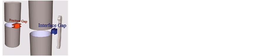
Figure 2. 3-D schematic of the interface (blue arrow) and fracture gap (red arrow).
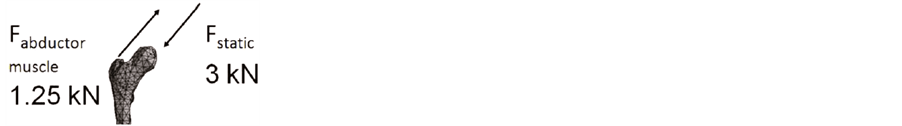
Figure 3. Loads used in the FEM.
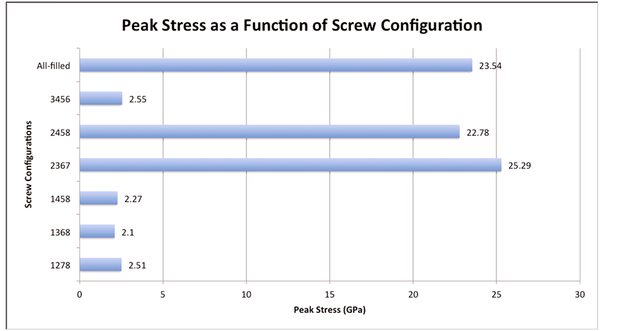
Figure 4. Peak stress as a function of screw configuration.

Figure 5. Stress concentration in config. 1368 with 0 mm interface gap and 0.1 mm fracture gap (top) and 2 mm fracture gap (bottom).
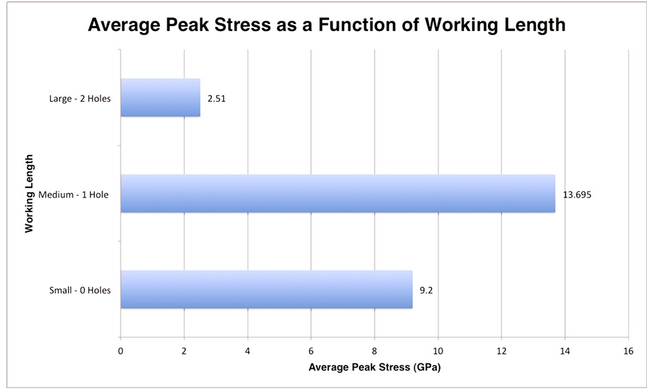
Figure 6. Peak stress as a function of working length.

Figure 7. Peak stress as a function of interface gap.
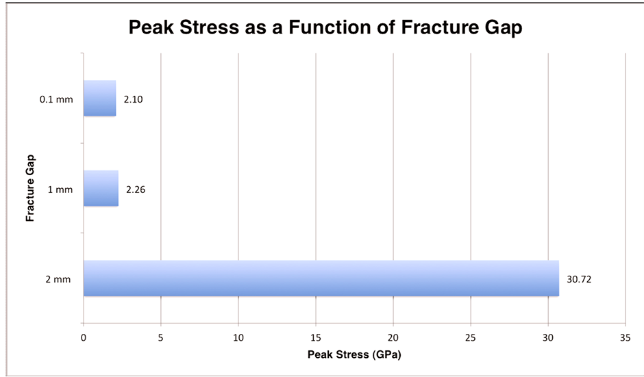
Figure 8. Peak stress as a function of fracture gap.
one-time massiveload, and therefore measurement of the stress or strain experienced by the plate-screw construct may be a better means to study plate failure.
The first variable examined was the locked screw configuration and its influence on the stress experienced by the LCP construct. Initially, the recommendations for screw configurations of locked plating in the literature were mostly based on biomechanical studies of compression plating or empirical evidence [5] [7] [10] [12] [16] -[20] . One basic concept found throughout the literature is that more screws does not equate to more stability [3] [11] [12] . This can clearly be seen in the fact that the 12345678 configuration experienced one of the highest peak stresses (23.54 GPa). In all seven configurations with a fracture gap of 0.1 mm and interface gap of 0 mm, the peak stress were seen at the screw-plate interface by the locked hole nearest the fracture (Figure 5). The most stable configuration with 0 mm interface gap and 0.1 mm fracture gap was found to be 1368 configuration. The 1368 configuration experienced a maximum stress of 2.10 GPa which is somewhat similar to the stress experienced by the 1278 (2.51 GPa), 1458 (2.27 GPa) and 3456 (2.55 GPa) configurations; however, it is approximately one tenth the peak stress seen in the 2367 (25.29 GPa) and 2457 (22.78 GPa) configurations. It is curious that the two configurations with the highest peak stress both had holes 1 and 8 omitted, and had holes 2 and 7 filled. Why these configurations led to the highest stress requires further investigation; however, it could be related to relative length of the plate. This concept which was described by Törnkvist et al. [7] suggests that widely spaced screws (in our case screws in holes 1 and 8) are more effective than adding single screws to a relatively shorter plate. This however does not explain the low peak stress seen in the 3456 configuration.
An attempt was made to elicit a relationship between working length and maximum stress by taking the average max stress for each working length (Figure 6). The average max stress for the large working length was 4 to 5 times less than that of the small and medium working lengths, respectively. These results suggests that with a minimal fracture and interface gap, a working length of 2 omitted holes on each side of the fracture may lead to significantly decreased peak stress in the plate-screw construct. These results are roughly in agreement with a FEM study conducted by Stoffel et al. [11] which recommended that for fracture gaps less than 2 mm (which includes even our largest fracture gap) that “one or even two plate holes near the fracture gap should be omitted to allow fracture motion and bone contact to occur”. They attributed this decrease in stress because the longer working lengths allowed for increased flexibility which led to bone contact between the two fragments with a 1 mm fracture gap [11] . Similar results were seen in a study conduct by Ellis et al. [16] , where an in vitro model using dynamic compression plating bridging plastic pipes in that strain was minimized when the screws were placed farthest from the fracture (increased working length) in the “no gap” model. While the findings of Ellis et al. [16] and other compression plating studies are important in this discussion, they do not necessarily translate to locked plating since the mechanical principles of fixation differ greatly between locked plating and compression plating as previously discussed.
The fracture gap is another factor that plays a role in bone plate construct stability. With the interface gap kept at 0 mm and the least stressed configuration of 2367, it was found that a fracture gap of 2 mm had the greatest stress of 30.72 GPa. This is more than a tenfold increase in the peak stress experienced by the fracture gaps of 0.1 mm and 1 mm (2.10 GPa and 2.26 GPa respectively). It was hypothesized that increasing the fracture gap with everything else remaining constant would lead to higher stress, which was what was found, especially going from 1 mm to 2 mm. With the 0.1 mm and 1 mm fracture gap, the stress was concentration at the locked screw-hole interface nearest the fracture as with all screw configurations with a 0.1mm fracture gap. In contrast, the 2 mm model showed the peak stress concentrated at hole 1 which is the most distal screw from the fracture. While our study focused solely on transversenon-comminuted fractures with minimal fracture gaps, Stoffel et al. [11] simulated comminuted fractures using a fracture gap of 6 mm. Based off their FEM of 6 mm fracture gaps, they found that the stress on the plate and screw increased with increasing working length in comminuted fractures. Ellis et al. [16] had similar findings with compression plating bridging both a 1 and 6 cm fracture gap in that the maximalstrain was lowest when screws were placed closest to the fracture.
The FEM showed that by increasing the interface gap led higher peak stress experienced by the construct. While increasing the interface gap from 0 to 2 mm led to nearly a three fold increase in the peak stress (2.10 to 6.11 GPa, respectively), which suggests that keeping the plate as close to the bone as anatomically possible will decrease the stress in the construct. This is in agreement with the current literature examining the effect of the distance between the plate and bone on construct stability [11] [13] .
Ahmad et al. [13] took the investigation a step further in the hopes to provide a more quantitative guideline in regards to interface gaps. They used multiple composite humerous sawbone models, each with a 10 mm diaphyseal gap bridged w/either a DCP flush to bone (control), LCP flush to bone, LCP 2 mm from bone, and LCP 5 mm from bone. All plates were attached via 3 screws to each bone fragment and then underwent compressive loading to failure, cyclical compression, cyclical torque and torque to failure. Ahmad et al. [13] found that with an interface gap of 5 mm there were lower loads to failure and significantly increased plastic deformation during cyclical compression. Therefore, they concluded that the plate should be placed at or less than 2 mm from the bone while still preserving the periosteal blood supply. While our study did not examine an interface gap greater than 2 mm, it is clear that increasing the interface gap, no matter the amount, will lead to greater stress on the LCP construct and hence a greater chance of construct failure.
This present study had a number of limitations, and areas to be improved upon in the future. The FEM will never be able to perfectly mimic the forces experienced by a femur in vivo, and similarly does not take into account any biological factors involved in fracture repair (i.e. callus formation, blood supply, etc.). This model was developed from a single human femur, and this unique bone geometry certainly influences the mechanics. Also, any type of statistical analysis was inhibited by the fact that n = 1 for this study. Lastly, this study lacked a cadaveric or animal experimental model to validate the results from the FEM.
5. Conclusion
This study sought to provide a framework to expand upon for future FEMs to exam the various factors that affect the mechanical stability of locking plate constructs. This study reaffirmed that more screws does not necessarily lead to decreased plate/screw stress. In this model, it was found that a working length of two holes on either side of the fracture led to the lowest peak stress. It also confirmed that as with external fixation increasing the distance between the plates, the bone (i.e. increasing interface gap) increases the stress experienced by the construct. Furthermore, this study confirmed that minimizing the fracture gap decreases the peak stresses seen by the plate screw construct. FEM holds significant promise in advancing the science of fracture fixation, and future FEM studies would benefit from cadaveric or animal models as a method to validate results.
References
- Egol, K.A., et al. (2004) Biomechanics of Locked Plates and Screws. Journal of Orthopaedic Trauma, 18, 488-493. http://dx.doi.org/10.1097/00005131-200409000-00003
- Miller, D.L., Goswami, T. and Prayson, M.J. (2008) Overview of the Locking Compression Plate and Its Clinical Applications in Fracture Healing. Journal of Surgical Orthopaedic Advances, 17, 271-281.
- Miller, D.L. and Goswami, T. (2007) A Review of Locking Compression Plate Biomechanics and Their Advantages as Internal Fixators in Fracture Healing. Clinical Biomechanics, 22, 1049-1062. http://dx.doi.org/10.1016/j.clinbiomech.2007.08.004
- Mehin, R., et al. (2009) A Biomechanical Study of Conventional Acetabular Internal Fracture Fixation versus Locking Plate Fixation. Canadian journal of surgery (Journal Canadien de Chirurgie), 52, 221-228.
- Wagner, M. (2003) General Principles for the Clinical Use of the LCP. Injury, 34, B31-B42. http://dx.doi.org/10.1016/j.injury.2003.09.023
- Perren, S.M. (2002) Evolution of the Internal Fixation of Long Bone fractures. The Scientific Basis of Biological Internal Fixation: Choosing a New Balance between Stability and Biology. The Journal of Bone and Joint Surgery (British Volume), 84, 1093-1110. http://dx.doi.org/10.1302/0301-620X.84B8.13752
- Tornkvist, H., Hearn, T.C. and Schatzker, J. (1996) The Strength of Plate Fixation in Relation to the Number and Spacing of Bone Screws. Journal of Orthopaedic Trauma, 10, 204-208. http://dx.doi.org/10.1097/00005131-199604000-00009
- Fulkerson, E., et al. (2006) Fixation of Diaphyseal Fractures with a Segmental Defect: A Biomechanical Comparison of Locked and Conventional Plating Techniques. The Journal of Trauma, 60, 830-835. http://dx.doi.org/10.1097/01.ta.0000195462.53525.0c
- Sommer, C., et al. (2004) Locking Compression Plate Loosening and Plate Breakage: A Report of Four Cases. Journal of Orthopaedic Trauma, 18, 571-577. http://dx.doi.org/10.1097/00005131-200409000-00016
- Sommer, C., et al. (2003) First Clinical Results of the Locking Compression Plate (LCP). Injury, 34, B43-B54. http://dx.doi.org/10.1016/j.injury.2003.09.024
- Stoffel, K., Dieter, U., Stachowiak, G., Gächter, A. and Kuste, M.S. (2003) Biomechanical Testing of the LCP—How Can Stability in Locked Internal Fixators Be Controlled? Injury, 34, 11-19. http://dx.doi.org/10.1016/j.injury.2003.09.021
- Gautier, E. and Sommer, C. (2003) Guidelines for the Clinical Application of the LCP. Injury, 34, 63-76. http://dx.doi.org/10.1016/j.injury.2003.09.026
- Ahmad, M., Nanda, R., Bajwa, A.S., Candal-Couto, J., Green, S. and Hui, A.C. (2007) Biomechanical Testing of the Locking Compression Plate: When Does the Distance between Bone and Implant Significantly Reduce Construct Stability? Injury, 38, 358-364. http://dx.doi.org/10.1016/j.injury.2006.08.058
- Senalp, A.Z., Kurtaran, O. and Kurtaran, H. (2006) Dynamic and Fatigue Behavior of Newly Designed Stem Shapes for Hip Prosthesis Using Finite Element Analysis. Materials & Design, 28, 1577-1583. http://dx.doi.org/10.1016/j.matdes.2006.02.015
- Ratner, B., Hoffman, A.S., Schoen, F. and Lemons, J. (1996) Biomaterial Science—An Introduction to Materials in Medicine. Academic Press, San Diego.
- Riemer, B.L., Butterfield, S.L., Burke, C.J. and Mathews, D. (1992) Immediate Plate Fixation of Highly Comminuted Femoral Diaphyseal Fractures in Blunt Polytrauma Patients. Orthopedics, 15, 907-916.
- Ellis, T., Bourgeault, C.A. and Kyle, R.F. (2001) Screw Position Affects Dynamic Compression Plate Strain in an in Vitro Fracture Model. Journal of Orthopaedic Trauma, 15, 333-337. http://dx.doi.org/10.1097/00005131-200106000-00005
- Field, J.R., Törnkvist, H., Hearn, T.C., Sumner-Smith, G. and Woodside, T.D. (1999) The Influence of Screw Omission on Construction Stiffness and Bone Surface Strain in the Application of Bone Plates to Cadaveric Bone. Injury, 30, 591-598. http://dx.doi.org/10.1016/S0020-1383(99)00158-8
- Hertel, R., Eijer, H., Meisser, A., Hauke, C. and Perren, S.M. (2001) Biomechanical and Biological Considerations Relating to the Clinical Use of the Point Contact-Fixator—Evaluation of the Device Handling Test in the Treatment of Diaphyseal Fractures of the Radius and/or Ulna. Injury, 32, 10-14. http://dx.doi.org/10.1016/S0020-1383(01)00121-8
NOTES

*Corresponding author.