Modern Instrumentation
Vol.2 No.1(2013), Article ID:27461,4 pages DOI:10.4236/mi.2013.21003
Gate Lip Hydraulics under Sluice Gate
1Department of Dam and Water Resources, College of Electronic Engineering, University of Mosul, Mosul, Iraq
Email: ahmedymaltaee@gmail.com
Received October 10, 2012; revised December 5, 2012; accepted December 14, 2012
Keywords: Sluice Gate; Coefficient of Contraction; Coefficient of Velocity; Coefficient of Discharge
ABSTRACT
This paper present the effect of the lower gate lip on the coefficient of contraction, velocity and discharge which have been made in a rectangular flume with four gates opening from (2 to 4.5) cm, five different discharges from (6.2 to 18.15) l/s and five different gate cases (vertical and inclined vertically) by angle (45)˚ with and opposite flow direction with horizontal and sharp lower lip. The values of coefficients of contraction (Cc) and discharge (Cd) increases when gate slope increases with flow direction and the lower lip is horizontal, these increases are (16)% and (18)% respectively, while these values decreases when gate slope increases opposite flow direction and the lower lip is horizontal these decreases are (13)% and (11)% respectively. The values of coefficient of velocity (Cv) remain constant and don’t effect with changes of gate slope or gate lip.
1. Introduction
Gates have been used as a hydraulic structures to control and rises the U.S. water level, so, it s used in irrigation structures to ensure water to the lands.
The gates design as a flow get out under them, so, they called under flow gates which is hydraulically similar to the discharge through orifice, and also it may design to allow the water flows over it, so, the gates called the over flow gates, which is hydraulically similar to the flow over weirs.
Because these important, more authors’ deals with studied the flow hydraulics for vertical gates but with developed since and wildly used of gates in more of hydraulic structures, so, there is very important to study another cases such as the inclined gates.
Many studies have been made to study free and submerged low discharged through the sluice gate, some of these studies deals with the discharge characteristics of the sluice gate Rajaratnam & Subramanya [1] others deals with characteristics of the stream emerging from under the gate, concentrating on the coefficients of contraction, discharge and velocity of this stream of flow Fangmeier & Strelkoff [2]; Isaacs [3]; Rajaratnam [4]; Cheng et al. [5]; Masliyah et al. [6]; Montes [7]; Hager [8].
In this paper the flow characteristics of coefficient of contraction, coefficient of velocity and coefficient of discharge have been studied for flow pass underneath vertical and inclined sluice gates with (45)˚ angle with and opposite flow.
2. Experimental Work
The Experiments take place in a rectangular flume with (10) m long, (0.3) m wide and (0.45) m depth with glass walls and aluminum bed, contain weir (0.3) m wide and (0.15) m depth in the DS of the channel for discharge measurements.
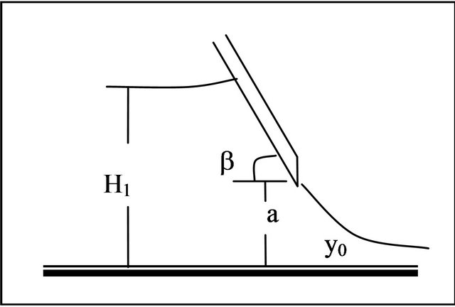
The gate has been made from wood (30) cm wide, (40) cm height and (6) mm, thickness with straight edge and installed at (2.9) m from the channel entrance vertically and inclined vertically at (45)˚ with flow direction and opposite it with horizontal and sharp edge Figure 1 shows a definition sketches for all cases.
Four gates opening (a) used (2, 3, 4, 4.5) cm and five US water levels (H0) between (18.9 and 28.9) cm for all gate cases.
More than (60) experiments have been done and from which all theoretical calculated has been made.
3. Coefficients of Contraction
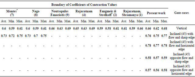
From the experimental results shows the values of (Cc) for vertical gate changed from (0.625 to 0.685) and the average value (0.661). The values of (Cc) for other gate cases shows in Table 1.
The values of (Cc) with (H0/a) for all cases have been drawn in Figure 2, it could be seen that the values of (Cc) increases when gate slope increases with flow direction and horizontal gate lip, while decreases when gate slope increases opposite flow direction and horizontal gate lip .
The average values of (Cc) for gate inclined with flow direction increases by (18)% for horizontal edge and
 (a)
(a)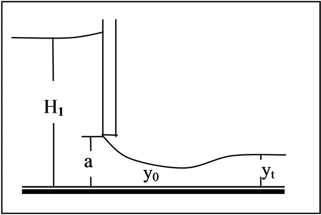 (b)
(b)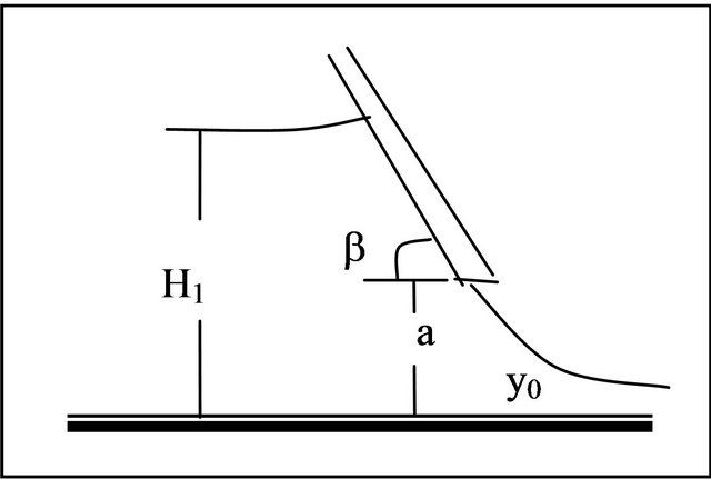 (c)
(c)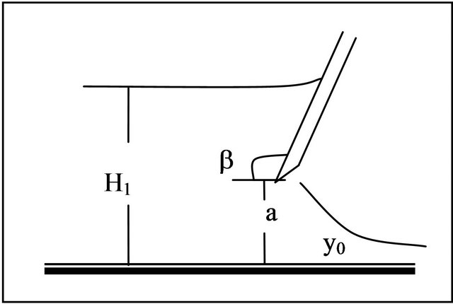 (d)
(d)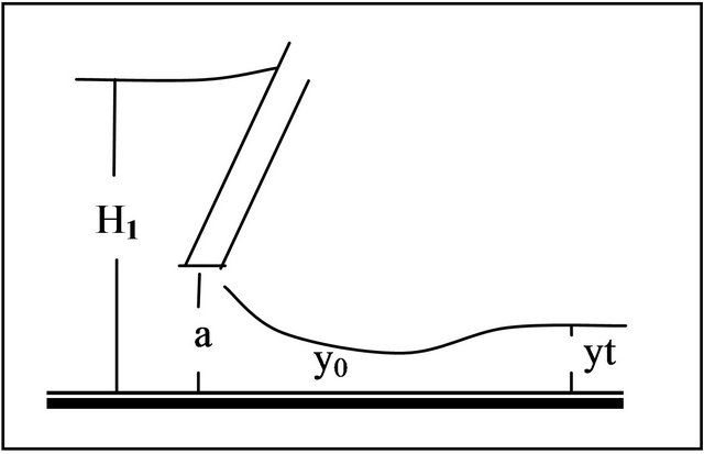 (e)
(e)
Figure 1. Definition sketch of sluice gate. (a) Vertical with horizontal edge; (b) Inclined with flow direction and sharp edge; (c) Inclined opposite flow direction and sharp edge; (d) Inclined with flow direction and horizontal edge; (e) Inclined opposite flow direction and horizontal edge.
Table 1. Boundary of coefficients of contraction values.
(16)% for sharp edge compared with vertical gate.
While decreases by (13)% for horizontal edge and (11.8)% for sharp edge when gate inclined opposite flow direction because effected the boundary layer (Nago [8]; Montes [7]).
Table 1 shows compared the values of (Cc) for the present work with Rajaratnam & Subramanya [1]; Fangmeier & Strelkoff [2]; Rajaratnam [4]; Noutsopoulos & Fanarotis [10]; Nago [9] and Montes [7]. The experimental values for the present work is similar with some of past research and different from others because the nature of gate and the experimental channel used Hager [8], so, these values higher than the theoretical by (6)% for horizontal edge and (4)%) for sharp edge compared with vertical gate. This different observed by Fangmeier & Strelkoff [2], Rajaratnam [4], Isaacs [3], Fanariotis & Noutsopoulos [10] and Cheng et al. [5], because of the boundary layer in the channel bed.
Boundary layer in the channel sides and upstream of gate contact with water surface (Betts [11]; Montes [7]).
4. Coefficient of Velocity
The experimental values of (Cv) changed from (0.925 to 0.999) in Table 2. This little different in values shows the actual velocity was similar with theoretical. Figure 3, shows the values of (Cv) with (H0/a) for all cases, all values variation between (0.92 to 1).
5. Coefficient of Discharge
The values of (Cd) actually is similar with (Cc) and shows these values for vertical gate changed from (0.596 to 0.674) and the average value (0.645) while for other gate cases shows in Table 3, and the values of (Cd) with (H0/a) for all cases have been drawn in Figure 4, it could be seen that the values of (Cd) increases when gate slope increases with flow direction and horizontal gate lip, with decreases when gate slope increase opposite flow direction and horizontal gate lip.
The average values of (Cd) for gate inclined with flow direction increases by (17.8)% for horizontal edge and (17)% for sharp edge compared with vertical gate. While decreases by (12.4)% for horizontal edge and (10.8)% for sharp edge when gate inclined opposite flow direction, because effected of the boundary layer (Nago [8]; Montes [7]).
Table 3, shows compared the values of (Cd) for present work with (Rajaratnam&Subramanya [1]; Fangmeier & strelkoff [2]; Rajaratnam [4]; Isacs [3]; Nago [8];
Cheng et al. [5]; Mosliyah et al. [6] and Hager [8]).
The experimental values for the present work are higher than values of past research because the nature of gate and the experimental channel used Hager [9].
6. Conclusions
The average values of (Cc) for gate inclined with flow direction and horizontal edge increases by (18)% and for sharp edge increases by (16)%, While decreases by(13)% for horizontal edge and (11.8)% for sharp edge when gate inclined opposite flow direction, so, the experimenttal values of (Cc) is greater than theoretical values by (6)% for horizontal edge and (4)% for sharp edge.
The average values of (Cv) remain constant for horizontal and sharp edge.
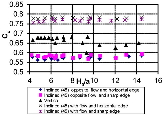
Figure 2. Variation of (Cc) with (H0/a) for all cases.
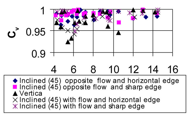
Figure 3. Variation of (Cv) with (H0/a) for all cases.
Table 2. Boundary of Coefficients of Velocity Values.
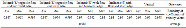
Table 3: Boundary of coefficients of discharge values.
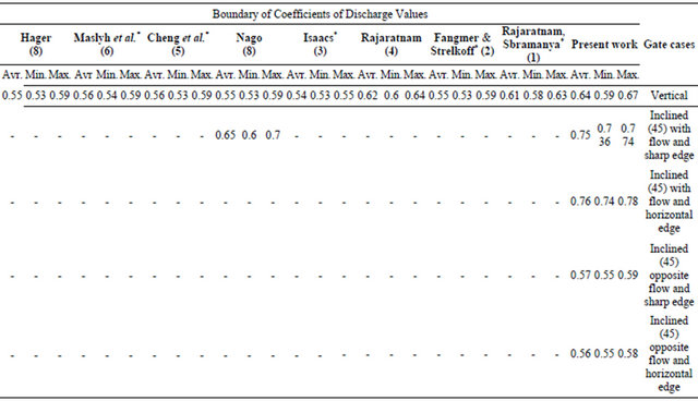
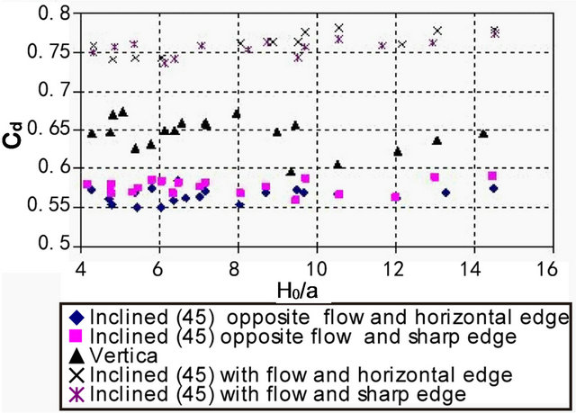
Figure 4. Variation of (Cd) with (Ho/a) for all cases.
The average values of (Cd) for gate inclined with flow direction and horizontal edge increases by (17.8)% and for sharp edge increases by (17)%. While decreases by (12.4)% for horizontal edge and (10.8)% for sharp edge when gate inclined opposite flow direction.
REFERENCES
- N. Rajaratnam and K. Subramanya, “Flow Equation for the Sluice Gate,” Journal of Irrigation and Drainage Engineering, Vol. 93, No. 9, 1967, pp. 167-186.
- D. D. Fangmeier and T. S. Strelkoff, “Solution for Gravity Flow under a Sluice Gate,” Journal of the Engineering Mechanics Division, Vol. 94, No. 2, 1967, pp. 153-176.
- L. T. Isaacs, “Numerical Solution for Flow under Sluice Gates,” Journal of the Hydraulics Division, Vol. 103, No. 5, pp. 1977, pp. 473- 481.
- N. Rajaratnam, “Free Flow Immediately Below Sluice Gates,” Journal of the Hydraulics Division, Vol. 103, No. 4, 1977, pp. 345-351.
- A. H. D. Cheng, J. A. Liggett and P. L.-F. Liu, “Boundary Calculations of Sluice and Spillway Flows,” Journal of the Hydraulics Division, Vol. 107, No. 10, pp. 1163- 1178.
- J. H. Masliyah, k. Nandakuma, F. Hemphill and L. Fung, “Body-Fitted Coordinates for Flow under Sluice Gates,” Journal of the Hydraulics Division, Vol. 111, No. 6, 1985, pp. 922-933.
- J. S. Montes, “Irrotational Flow and Real Fluid Effects under Planar Sluice Gates,” Journal of the Hydraulics Division, Vol. 123, No. 3, 1997, pp. 219-232.
- W. H. Hager, “Underflow of Standard Sluice Gate, “Experiments in Fluids,” Experiments in Fluids, Vol. 27, No. 4, 1999, pp. 339-350.doi:10.1007/s003480050358
- H. Nago, “Influence of Gate Shapes on Discharge Coefficients,” Proceedings of Japan Society of Civil Engineers, 1978, pp. 59-71.
- G. K. Noutsopoulos and S. Fanariotis, “Discussion of Free Flow Immediately below Sluice Gates,” Journal of the Hydraulics Division, Vol. 104, No. 3, 1978, pp. 451- 455.
- P. L. Betts, “Discussion of Numerical Solution for Flow under Sluice Gates,” Journal of the Hydraulics Division, Vol. 104, No. 2, 1978, pp. 313-315.