Modern Mechanical Engineering
Vol.3 No.4(2013), Article ID:39036,5 pages DOI:10.4236/mme.2013.34021
Cycloidal Magnetic Gear Speed Reducer
Instituto de Ingenieria, Universidad Nacional Autonoma de Mexico, Mexico City, Mexico
Email: rcu@pumas.ii.unam.mx
Copyright © 2013 Ricardo Chicurel-Uziel. This is an open access article distributed under the Creative Commons Attribution License, which permits unrestricted use, distribution, and reproduction in any medium, provided the original work is properly cited.
Received August 10, 2013; revised September 13, 2013; accepted September 27, 2013
Keywords: Magnetic Transmissions; Cycloidal Speed Reducers; Magnetic Gears
ABSTRACT
A cycloidal speed reducer employing gears with permanent magnets acting as teeth is described. The magnets, which have their axes radially oriented in both the orbiting gear and the fixed internal gear, are inserted in holes drilled in nonmagnetic rims without protruding from the cylindrical exposed surfaces. Because the orbiting gear is not restrained radially, it contacts the fixed gear and rolls on its inner surface. A normal force is developed at the contact point between the gears to balance the magnetic attraction and the centrifugal force of the orbiting gear. The friction available due to this normal force increases the transmission’s torque capacity, which is further increased by elimination of the gap between the gears. Also, the radial load on the supporting orbiting gear bearing is eliminated. A prototype with a reduction ratio of 26 is being tested.
1. Introduction
Speed reducers based on the magnetic transmission of forces instead of on conventional mechanical elements such as gears, chains and belts, are becoming increasingly attractive. In addition to offering the advantages of quiet operation, sustainment of overloads without damage, and not requiring lubrication, their efficiency and load capacity in theory appear not to be very far behind those of mechanical gearboxes [1,2]. Speed reducers employing “gears” having radially oriented permanent magnets in alternating polarities are described in a number of patents [3-6]. In other magnetic transmissions, permeable iron elements are used to guide a magnetic field of alternating direction resulting from the rotation of a central wheel with permanent magnets of alternating polarities causing a slow rotation of an exterior ring having a larger number of permanent magnets. Such is the case in the transmissions described in [1], and [7]. In reference [2], a magnetic cycloidal transmission with a topology similar to that of the speed reducer of this paper, is analyzed.
In the transmissions treated in all the previously mentioned references, the magnetic forces of attraction act across small gaps between the elements of the mechanism with no contact between them. In contrast with this characteristic, the magnetic gears of the cycloidal speed reducer treated in this paper contact one another due to the fact that the orbiting gear is free to move outwardly under the action of the magnetic attraction from the fixed gear and the centrifugal force. The advantages of this concept are pointed out in the description that follows. As will be seen, another feature incorporated in the speed reducer of this paper is a novel method of balancing the orbiting gear. This speed reducer is referred to as the UNAM cycloidal magnetic speed reducer.
2. Description of the UNAM Cycloidal Magnetic Speed Reducer
Figure 1 shows longitudinal and transverse cross sections of the UNAM cycloidal magnetic gear speed reducer. Each gear has an even number of radially mounted bar magnets distributed uniformly along its periphery in alternating polarities. A pair of N, S poles corresponds to a tooth of a conventional gear. The magnets, which are inserted in radial holes drilled in rims made of non magnetic stainless steel, do not protrude from the rims’ exposed cylindrical surfaces. The rim of the fixed gear is press fitted onto an outer ring made of permeable steel, and the rim of the orbiting gear is press fitted onto a central permeable steel disk. In cycloidal speed reducers, the orbiting gear is driven by a crank of the input high speed shaft. Because the speed ratio of the prototype magnetic unit built is rather large, 26:1, which would require a small crank radius, it was possible to omit a crank as such and use instead a tongue and groove arrangement as
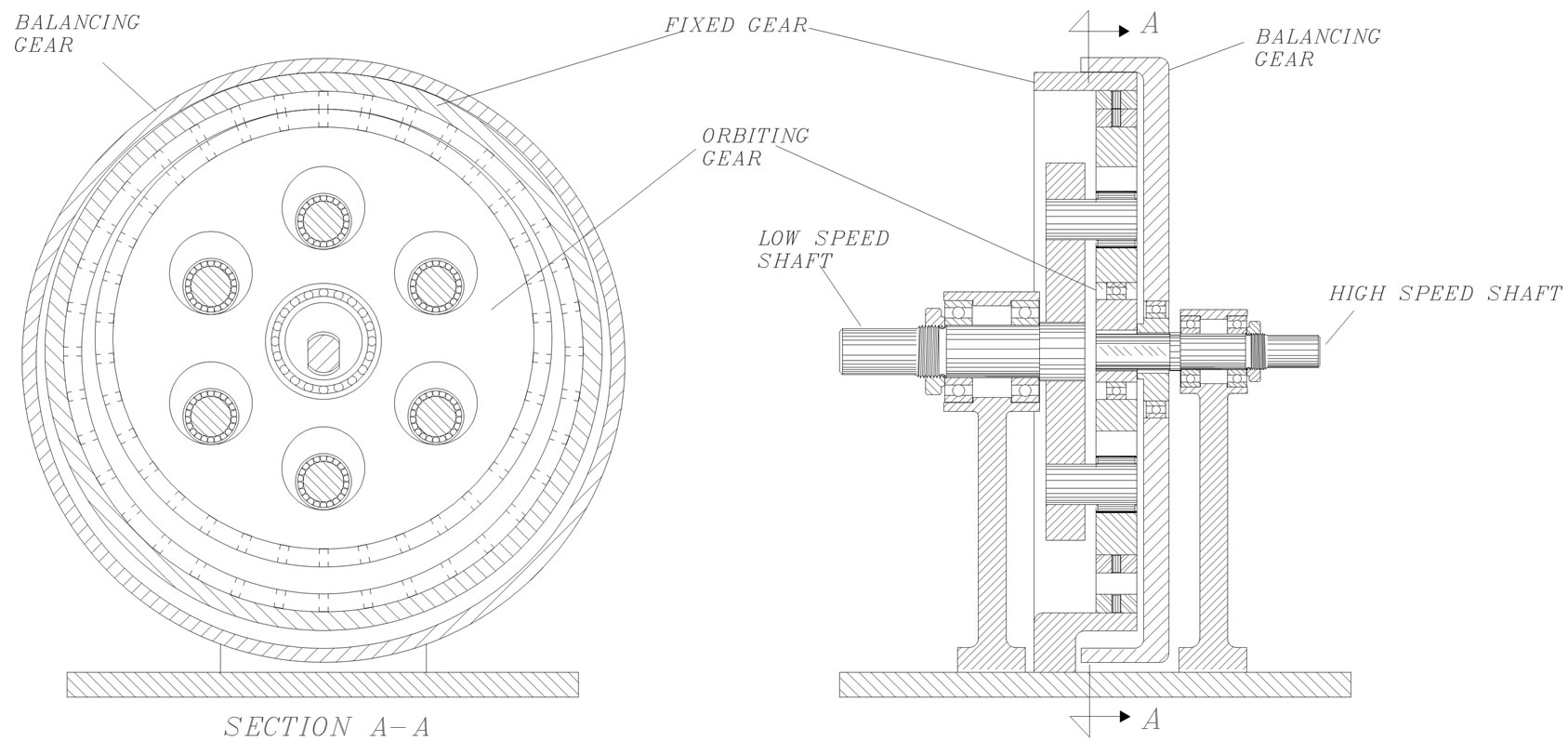
Figure 1. Cycloidal magnetic gear speed reducer. On the right is shown a longitudinal mid section and on the left the transverse cross section A-A.
depicted in Figure 1. The tongue is a segment of the input shaft with two parallel flat surfaces that penetrates in a groove on a central piece on which the orbiting gear is mounted by means of a ball bearing. The groove’s eccentricity on the central piece is equal to the gear’s orbiting radius. The groove’s length is slightly greater than the tongue width allowing the orbiting gear to be pulled radially by the magnetic force from the fixed gear. Thus a normal contact force between gears is produced. This normal force is further increased due to the centrifugal force on the orbiting gear when the unit is in operation. In this way, the orbiting gear rolls on the fixed gear. To avoid slip, the ratio of the diameters of the contact surfaces must be equal to the corresponding ratio of the number of magnet pairs. In this manner, the following advantages result: 1) the transmission’s torque capacity is increased because, in addition to the magnetic force between the gears, a frictional force associated with the normal contact force, is developed, 2) the radial load on the bearing supporting the orbiting gear is eliminated, 3) the need to accurately control the separation between the gears is eliminated, and 4) a greater magnetic attraction between magnets is obtained by elimination of the gap between them.
As in other cycloidal speed reducers, a disk with a number of axial pins on the low speed shaft which penetrate into an equal number of holes in the orbiting gear allows the transmission of the gear’s slow rotation to the output shaft, filtering out its circular translation. An apparently novel modification introduced in the present design is the incorporation of needle bearings on the pins to reduce frictional losses.
The centrifugal force of the orbiting gear is counterbalanced in the present speed reducer by means of an orbiting balancing wheel mounted on the input shaft in the same manner as the orbiting gear, that is, unrestrained to move radially, but in the opposite direction as the gear. The arrangement is shown in Figure 1. The centrifugal load on this wheel is resisted by the contact force between an interior rolling surface of its outer rim and an exterior surface in the stationary support that holds the fixed gear. The normal contact force exerted by the balancing wheel exactly cancels the force generated at the contact between the gears because the two are equal, opposite and collinear.
Three patents covering the above described features have been applied for; two in Mexico and one in the U.S.A. Design details of the UNAM prototype are found in Vazquez-Perez [8].
3. Torque Capacity
Following is an analysis to determine the output torque capacity of the speed reducer described above. Figure 2 is a free body diagram of the orbiting gear including its bearing and central grooved piece. The contact point of the gears is at the top of the figure, and it is assumed that the input shaft has a clockwise rotation. Fmr and Fmt are respectively the radial and tangential magnetic forces of attraction, Fc is the centrifugal force, N is the normal reaction force and Ff the friction force at the gears’ contact point, B is the force transmitted to the groove surface of the central piece by the tongue of the input shaft, and the fi are the reactions from the pin bearings of the output shaft disk. The origin of the reference x-y axes is on the axis of the input and output shafts, which are collinear.
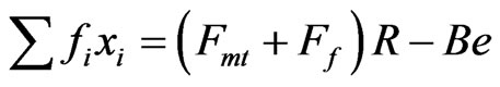
From the equilibrium in the x and y directions, the following equations are obtained:
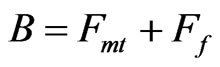 (1)
(1)
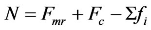 (2)
(2)
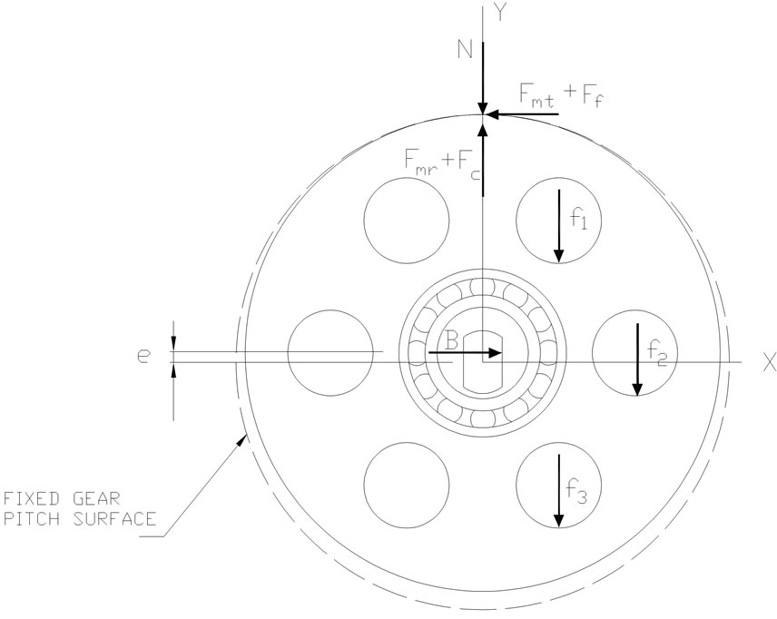
Figure 2. Free body diagram of the orbiting gear including its bearing and central grooved piece.
and, from the summation of moments about the origin:
 , (3)
, (3)
where R is the pitch radius of the fixed gear, e the orbiting gear eccentricity and the xi are the x-coordinates of the points of application of the fi.
Combining Equations (1) and (3):
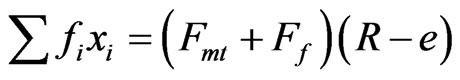 . (4)
. (4)
The summation on the left hand side of Equation (4) represents the output torque of the speed reducer, T. The maximum value that Fmt + Ff can have determines torque capacity based on gross slip, T1. This capacity is increased with speed of operation since N, and consequently the upper limit of Ff, are increased. Besides gross slip, contact between the gears may be lost when, in view of Equation (2), ∑fi just equals Fmr + Fc. This gives rise to a second limit on torque capacity, T2, which results from the lack of radial restraint of the orbiting gear.
For the purpose of analyzing the incipient breakdown of the transmission of power when T reaches either value T1 or T2, it is first observed that, for a given value of T = ∑fixi, it is not possible to determine the individual values of the fi. nor their sum. However, because of dimensional inaccuracies, one would expect only one pin of the output shaft disk to be loaded at one time. Suppose that that pin corresponds to the smallest xi = xmin as T1 or T2 is reached. At that moment, the point of contact between the gears ceases to be the instantaneous center of rotation of the orbiting gear. That center would shift to the point where the only active pin acts. Visualization of the ensuing rotation indicates that some heretofore unloaded pin farther from the y-axis would now take up the load and become still another instantaneous center of rotation. This readjustment process would be repeated until the only non zero fi becomes the one corresponding to the largest xi = xmax. Of course, xmax varies cyclically and its least value should be used to determine torque capacity. For example, if the number of pins on the output shaft disk is six, xmax fluctuates between (√3/2)r and r, where r is the radius of the circle of pin centers so xmax would be (√3/2)r in that case.
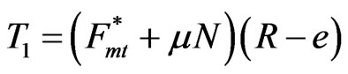
To determine T1, Equation (3) is specialized for the gross slip condition as:
 , (5)
, (5)
Where Fmt* is the maximum value that Fmt can have and µ is the friction coefficient at the contact between gears.
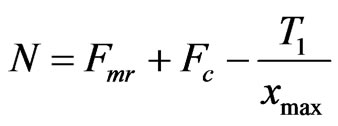
If fa represents the force acting on the active pin corresponding to xmax, Equation (2) may be written as:
 . (6)
. (6)
Substituting the expression for N given by Equation (6) in Equation (5), and solving for T1:
 (7)
(7)
To determine T2, N is set equal to zero and T2/xmax is substituted for ∑fi in Equation (2), resulting in:
 (8)
(8)
From Equation (8), it is seen that, as in the case of gross slip, the torque limit due to gear separation is increased with speed of operation.
To compare the present design with one in which a gap between gears is maintained and the moving gear is restrained from radial movement, the torque limit for gross slip for that case, T10, will now be compared to the limits T1, T2 given by Equations (7), (8). An expression for T10 may be obtained simply by setting µ = 0 in Equation (7):
 . (9)
. (9)
Then,
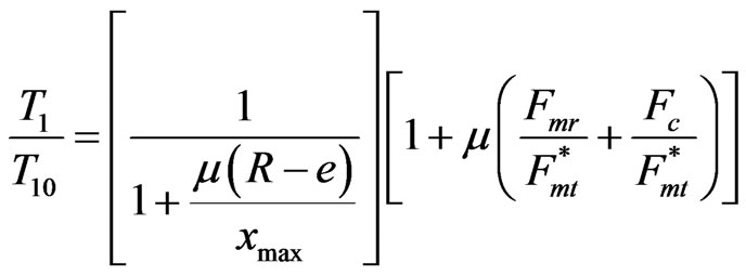 , (10)
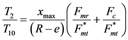 . (11)
For the UNAM prototype, (R-e)/xmax = 1.80 and Fmr/ Fmt* = 4.29. Therefore, in that case:
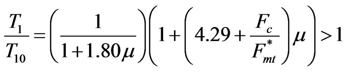 ,
,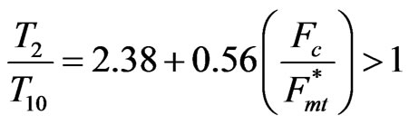 .
.
These results show the benefit with respect to torque capacity of eliminating the radial restraint on the orbiting gear.
4. Speed reducer Prototype
A prototype of the UNAM cycloidal magnetic speed reducer was built with the following design specifications:
• Number of magnet pairs in fixed gear—27
• Number of magnet pairs in orbiting gear—26
• Fixed gear pitch diameter (ID)—162 mm
• Orbiting gear pitch diameter (OD)—156 mm
• Radius of circle of pin centers—50 mm
• Magnets—Neodymium alloy, 6 mm dia × 5 mm long
From the gears’ pitch diameters, the orbiting gear eccentricity is found to be 3.0 mm. The orbiting gear mass including its central piece and bearing is 2.124 kg. The mass of the balancing wheel, also including its central piece and bearing, is 4.092 kg. Its required eccentricity in order that the product of mass and eccentricity be the same as for the orbiting gear, is 1.56 mm. The other condition required for balancing is that the centers of mass of both components lie in the same transverse plane on opposite sides of the axis of the machine. These conditions were closely satisfied.
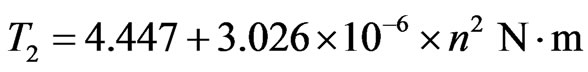
An exploded view is shown in Figure 3 and a photograph of the assembled unit in Figure 4.
The radial magnetic force of attraction between the gears, Fmr, was determined experimentally by letting the orbiting gear hang from the fixed gear and adding weights until it dropped. The result was Fmr = 102.7 Nt.
Also, as pointed out before, Fmr = 4.29 , a result found from tests on a pair of magnets, so
  = 23.9 Nt.
Applying Equation (7), the torque limit, T1, for three values of the friction coefficient, is:
 (12a)
(12a)
 (12b)
(12b)
 (12c)
(12c)
where n is the rpm of the high speed shaft. The value µ = 0 refers to non contacting gears and does not apply to the UNAM reducer.
Also, from Equation (8), the torque limit T2 is in this case:
 (13)
(13)
From Equations (12) and (13), one may conclude that the torque capacity of the UNAM reducer is limited by gross slip rather than gear separation. Also, the increased torque capacity due an unrestrained orbiting gear is appreciated when comparing Equations (12b), (12c) with (12a).
The centrifugal force effect may be considerable. For example, for µ = 0.1, the torque capacity is increased by a factor of 3.64 when n increases from 0 to 3600 rpm.
5. Tests
The prototype speed reducer has undergone limited testing that revealed the need to make some corrections. Inaccuracies detected in the low speed shaft and disk assembly mandate certain reworking. The balancing wheel exhibits a slight wobbling motion which will require a minor design modification. In the meantime tests were run at rather low speeds without the balancing wheel, using the set up shown in Figure 5. The high speed end is driven by a DC motor with a floating stator mounted on bearings but restrained from rotation by means of an arm pressing on a force transducer. The output, low
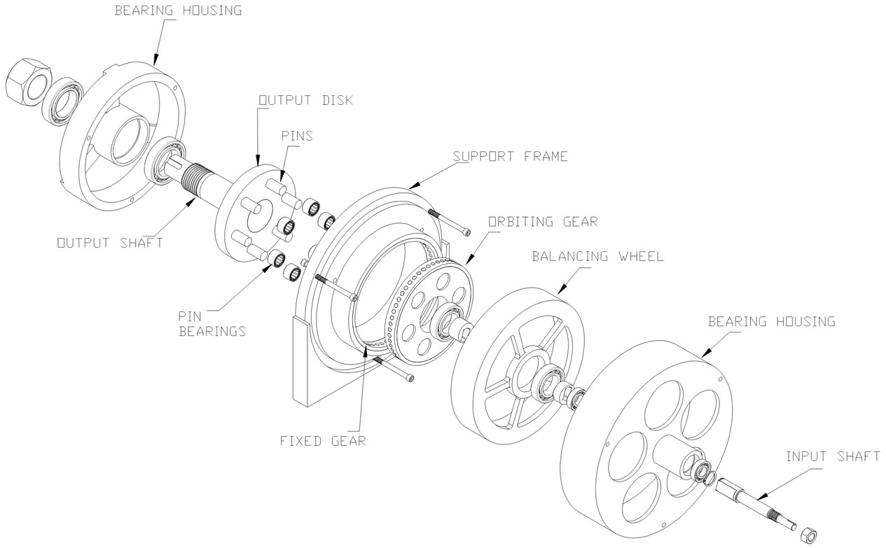
Figure 3. Exploded view of reducer prototype.
Figure 4. UNAM speed reducer.
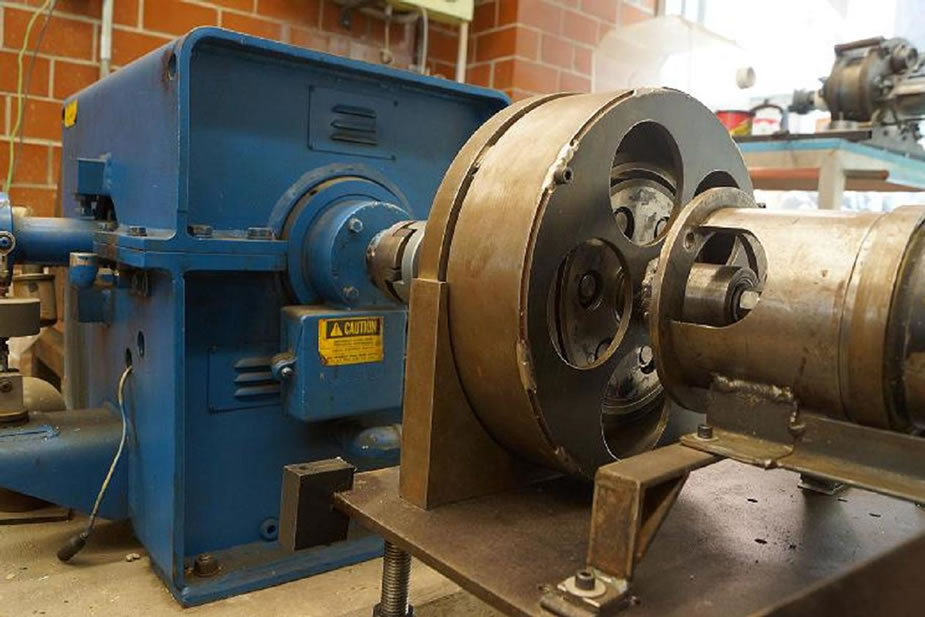
Figure 5. Test setup.
speed shaft is connected to an absorption dynamometer. The output torque is determined in a similar manner as the input torque, that is, by means of an arm of the dynamometer housing pressing on a force transducer. Preliminary results are shown in Table 1.
6. Conclusions
The UNAM cycloidal magnetic speed reducer incorporates novel features which confer it advantages over the state of the art. The most radical feature is the fact that the orbiting gear is free to move outwardly under the action of the magnetic attraction from the fixed gear and the centrifugal force, allowing it to contact the fixed gear and roll thereon. One effect is an increase in torque capacity due to a frictional force associated with the normal contact force. Another effect is the elimination of the radial load on the bearing supporting the orbiting gear resulting from the magnetic attraction between the gears and the centrifugal force on the orbiting gear. Additionally, the need to accurately control the separation between the gears is eliminated, and a greater attraction between magnets results from the elimination of the gap between them. The balancing wheel incorporated in the machine appears to be quite effective; however, a minor
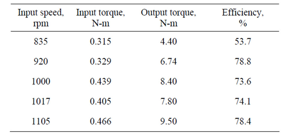
Table 1. Speed reducer test results.
design modification will be required to suppress a wobbling motion that has been observed. An analysis showed that, by eliminating the radial restraint on the orbiting gear, the output torque capacity is increased.
Test results, although preliminary, are encouraging.
7. Acknowledgements
This investigation was carried out with funding from the program PAPIIT (Program to Support Projects in Research and Technological Innovation) of the Universidad Nacional Autonoma de Mexico. The valuable contributions of Professors Gabriel Ascanio and Filiberto Gutierrez are gratefully acknowledged. The author is indebted to the students Jonathan Arenas, Luis A. Vazquez, Alvaro Nuñez and Omar Sanchez, who participated in the design, construction and testing of the speed reducer prototype as well as many other tasks related to the project.
REFERENCES
- P. O. Rasmussen, et al, “Development of a High Performance Magnetic Gear,” IEEE Transactions on Industry Applications, Vol. 41, No. 3, 2005, pp. 764-770. http://dx.doi.org/10.1109/TIA.2005.847319
- F. T. Jorgensen, et al, “The Cycloid Permanent Magnetic Gear,” IEEE Transactions on Industry Applications, Vol. 44, No. 6, 2008. pp. 1659-1665. http://dx.doi.org/10.1109/TIA.2008.2006295
- T. B. Martin Jr., “Magnetic Transmission,” US Patent No. 3,378,710, 1968.
- W. J. Mabe Jr., “Magnetic Transmission,” U.S. Patent No. 5,013,949, 1991.
- C. P. Cho and R. A. Bedingfield, “Permanent Magnet Torque/Force Transfer Apparatus,” Patent No. 5,569,111, 1996.
- G. Valmor da Cunha, “Orbital Magnetic Speed Change,” US Patent No. 8,210,980 B2, 2012.
- K. Atallah, “Magnetic Gear,” US Patent No. 7,973,441 B2, 2011.
- L. A. Vazquez-Perez, “Diseño y Construccion de un Redactor de Velocidad Cicloidal Magnetico Balaqnceado,” Master’s Degree Thesis, Universidad Nacional Autonoma de Mexico, 2013.