Modern Mechanical Engineering
Vol.2 No.2(2012), Article ID:19026,6 pages DOI:10.4236/mme.2012.22006
Millimeter Scale MEMS Air Turbine Generator by Winding Wire and Multilayer Magnetic Ceramic Circuit
College of Science and Technology, Nihon University, Chiba, Japan
Email: uchikoba@eme.cst.nihon-u.ac.jp
Received February 19, 2012; revised March 9, 2012; accepted March 20, 2012
Keywords: MEMS; Air Turbine; Generator; Multilayer Ceramic; Ferrite; Dr. Blade; Screen Print
ABSTRACT
This paper provides a new system and concept concerning to MEMS air turbine power generator. The generator was composed of the MEMS air turbine and the magnetic circuit. The magnetic circuit was fabricated by multilayer magnetic ceramic technology and achieved monolithic structure which included high permeability material and three dimensional helical conductor patterns inside. Although the output power was micro watt class, some features were extracted by comparing to the simple winding wire type magnetic circuit. In the power density measurement, almost same output power density was extracted though the turn number of the winding wire type was more than that of monolithic type. Also the resistance of the conductor was quarter of the winding type. The maximum output voltage and the maximum power of the monolithic generator was 6.2 mV and 1.92 µVA respectively. The DC conductor resistance was 1.2 Ω. The energy density was 0.046 µVA/mm3. The appearance size of the monolithic type was 3.6, 3.4, 3.5 mm, length, width and height respectively.
1. Introduction
Strong demand for miniaturized power sources becomes remarkable with progressive miniaturization of electronic equipment. Both small size and high power density are required for various applications. Although lithium secondary batteries have been used as the small and high power density sources, the power density is approaching the theoretical limit. Instead of the batteries, miniaturized generators have been studied as one of the candidate for exceeding the limit. Since UMGT (Ultra Micro Gas turbine) was presented by MIT group [1,2], a lot of MEMS (Micro Electro Mechanical Systems) micro generators have been studied widely.
Although a lot of studies of MEMS micro generator have been focused electrostatic types, the electromagnetic induction type shows low output impedance. Therefore, the electromagnetic induction type is more desirable than electrostatic type even in the miniaturized generator. Some outstanding studies were reported [3-12]. Among these studies, milli-watt to watt class generators were achieved. Also the complex three phase windings of copper conductor were reported.
In the commercial size generator, three dimensional wire windings such as helical structure and magnetic materials such as coil cores are used widely. However, in MEMS micro generator, the windings are usually designed in the planer structure such as spiral, meander or equivalent. Moreover the magnetic materials such coil cores have not been reported.
In the electromagnetic induction, the wide area and high magnetic flux density result large effect. Therefore, the combination of the helical structure that produces wide cross section and the magnetic material that concentrates magnetic flux is advantageous. Moreover, since the magnetic flux is focused in magnetic material of the small area, it is possible to shorten the conductor length. The shorter length results the less conductor loss.
The authors considered the three dimensional helical structure of the conductor and also introducing magnetic materials to the MEMS micro generator. Multilayer magnetic ceramic technology was used to realize helical windings and the magnetic material.
In this present study, the author fabricated a millimeter size generator with a MEMS micro air turbine and the multilayer magnetic ceramic circuit of the helical winding structure. As a fundamental benchmark study, we also prepared a simple winding wire circuit and compared output power, DC resistance of the conductor and so on. Although the obtained output power was micro watt level, some features were extracted. The obtained generator was monolithic structure in which high permeability magnetic material and helical winding conductor was formed. The output power density of the multilayer type achieved almost same in smaller volume with the less turn number of the coil than that of the winding wire. The DC resistance of the multilayer circuit was quarter of the simple winding wire type.
2. MEMS Air Turbine
The schematic illustration of the air turbine is shown in Figure 1. The air turbine part was made of 7 silicon layers. The upper layers were assigned for the air passage to the stator. The lower layers were formed for the passage to the fluid dynamic bearing system. The dimensions of the air turbine were 3.0, 3.0, 3.0 mm length, width and height, respectively.
The ring shape magnet was attached to the rotor and placed inside the hole of the stator. The shape of the rotor blade was referred to quasi-ultrasonic wings. The number of rotor blades were 20, the height was 100 μm.
The rotor and each layer were fabricated by a photolithography process. Aluminum etched pattern was used as resist films for high aspect ratio photolithograph, and resin photo resist was used for the low aspect ratio lithography. Each part layer was assembled by making use of the alignment pin and the hole, which reduced the dimensional error.
Figure 2 shows the component fabricated by photolithographic process. Also, Figure 3 shows the diameters of the rotor and the stator hole measured by a confocal microscope. The designed diameters of the rotor and stator were the 1590 μm and 1600 μm, respectively. And then the machined diameters were 1578.27 μm and 1603.32 μm, respectively. It is found that the error was quite small. In addition, Figure 4 shows the etched rotor structure observed by Scanning Electron Microscope (SEM). It is observed that the walls of the blade were formed perpendicular to the substrate.
3. Generator
3.1. Generator with Multilayer Magnetic Ceramic Circuit
At the bottom of the turbine, the multilayer magnetic ceramic circuit was mounted. The schematic illustration of the generator is shown in Figure 5. It is found that simple monolithic structure is achieved. The magnetic circuit is shown in Figure 6. The magnetic material was low temperature sintering nickel cupper zinc ferrite with the permeability of 900. Silver internal conductor was patterned inside the ferrite body. The average particle diameter of silver paste was 1μm. The magnetic circuit was made of 24 layers. The wiring conductor pattern was formed around the outer periphery on the 10 ferrite layers. The conductor was connected to the adjacent layer with via conductor. Therefore, the conductor formed helical structure inside the ferrite material. In addition, the upper 10 layers and the lower 4 layers were the ferrite without the conductor.
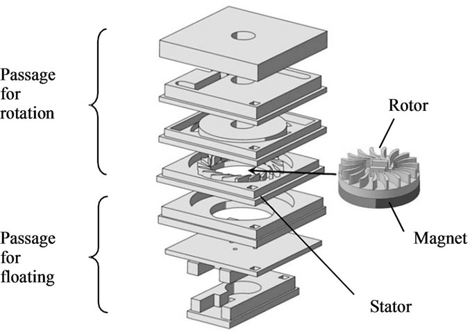
Figure 1. Schematic illustration of the MEMS air turbine.
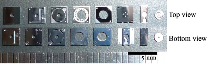
Figure 2. Components fabricated by photolithographic process.
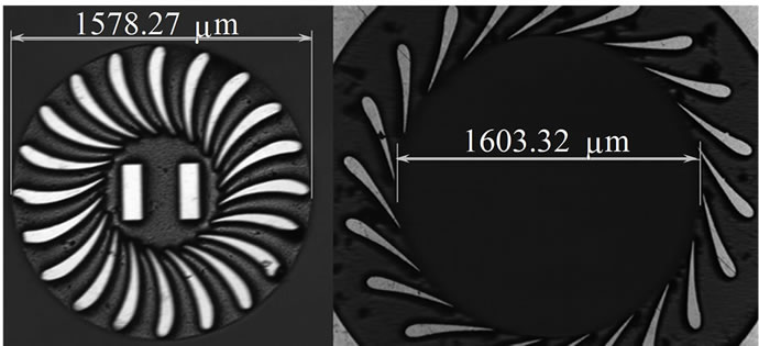
Figure 3. Diameters of the rotor and the stator hole measured by a confocal microscope.
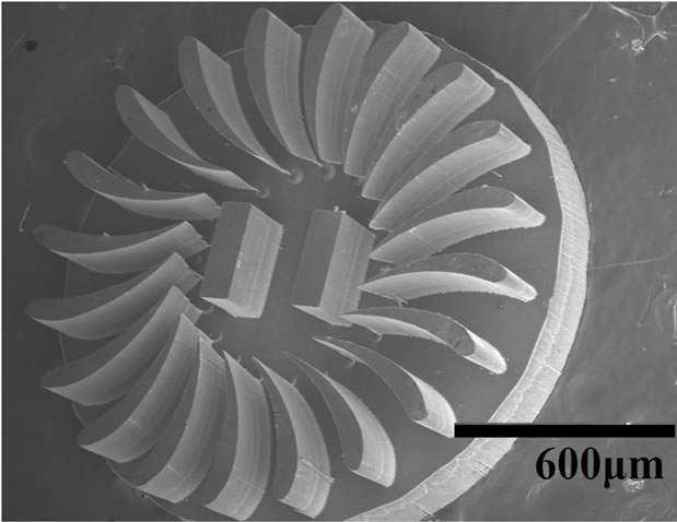
Figure 4. Etched rotor structure observed by Scanning Electron Microscope (SEM).
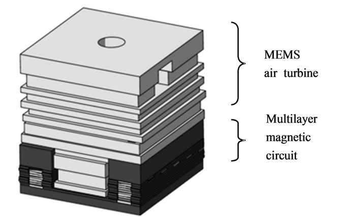
Figure 5. Schematic illustration of the monolithic structure by multilayer magnetic ceramic circuit.
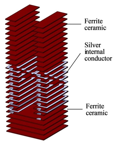
Figure 6. Magnetic circuit by multilayer magnetic ceramic.
The magnetic ceramic circuit was constructed by the ceramic green sheet process [13]. The word green sheet means a flexible sheet before firing, which is composed of ceramic powder and binder material. The compositional ratios of the slurry before tape casting are shown in Table 1. The tape cast method in this experiment was Dr. Blade method. Silver internal conductor was patterned on the green sheet by screen printing method. The number of turns was 18. The green sheet was stacked and compressed by CIP (Cold Isostatic Press). After the firing at 900 degrees Celsius, the magnetic circuit was obtained. the measured inductance and DC resistance were 6.25 μH and 1.2 Ω respectively. The dimensions of the generator combined of the micro air turbine and the multilayer magnetic ceramic circuit were 3.6, 3.4, 3.5 mm, length, width and height, respectively. The appearance of the multilayer magnetic ceramic circuit is shown in Figure 7. The appearance of the total generator including gas inlet pipes is shown in Figure 8.
3.2. Winding Wire Type Generator
As a benchmark sample, a simple winding wire type was
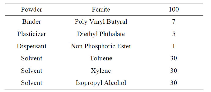
Table 1. Compositional weight ratios of the slurry before tape casting.
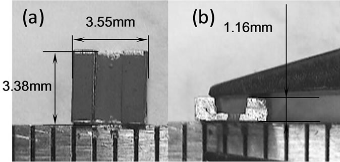
Figure 7. Appearance of the magnetic circuit including a pair of 9 turn-helical coils. (a) Top view; (b) Side View.
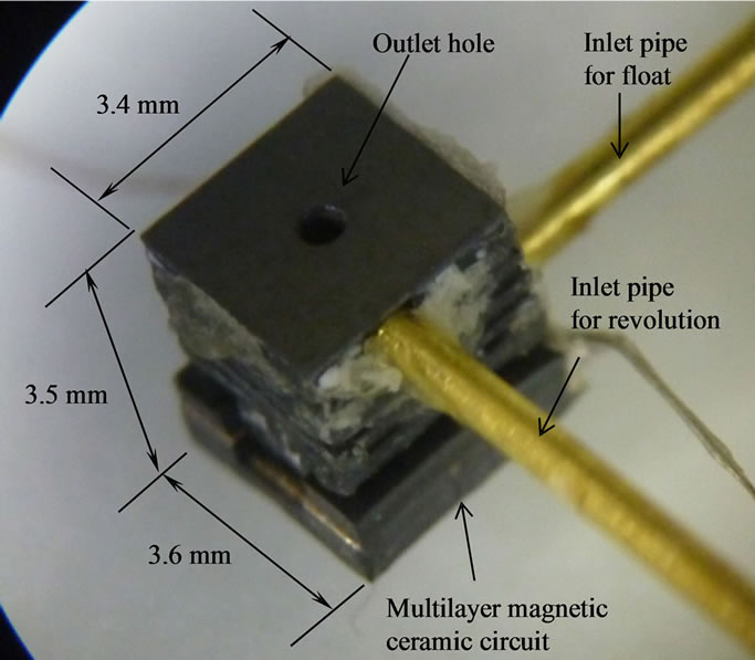
Figure 8. Generator with monolithic structure.
prepared. The poly urethane coated copper wire was wound around the air turbine. The turn number was 50, and the diameter of the wire was 50 μm. The schematic illustration of the winding wire type is shown in Figure 9. The measured inductance and DC resistance were 8.89 μH and 4.8 Ω. The appearance size was 4.4, 4.4, 4.1 mm, length, width and height, respectively.
4. Output Power Measurement
In the evaluation, a load resistance was connected to the output of the magnetic circuit. Since the output power
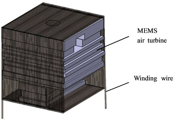
Figure 9. Schematic illustration of the winding wire type.
was depend on the value of the load resistance. The value of the resistance was adjusted to achieve the maximum output power. The output waveform was measured by an oscilloscope. The rotational speed was calculated from the output waveform. The power measurement was performed with changing the pressure of the inlet gas and the value of load resistance. During the measurement, the rotor was monitored by a high speed camera. The arrangement of the evaluation is shown in Figure 10.
5. Result and Discussion
5.1. Output Power
The rotational speed of the monolithic type was increased up to 0.28 MPa. Then the rotational speed was decreased. The reason will be discussed later. The maximum rotational speed was 58,000 rpm at 0.28 MPa. Figure 11 shows the output waveform at the maximum output voltage. At the load resistance of 20 Ω, the maximum power of the generator was 6.2 mV and 1.92 µVA, respectively.
On the contrary, in the case of winding wire type, the maximum rotational speed was 30,000 rpm on the condition of 0.20 MPa and it was constant up to 0.375 MPa. Figure 12 shows the output waveform at the maximum output voltage and the maximum power of the generator was 18.2 mV and 3.31 µVA, respectively. The load resistance was adjusted to 100 Ω for the maximum power.
Table 2 shows the comparison of the winding wire and the multilayer magnetic ceramic circuit. The energy density was 0.045 µVA/mm3. The value was almost same as the winding wire type. 50 turns of winding wire were required to achieve same energy density as the monolithic type of 18 turns. The multilayer magnetic circuit achieved same level energy density with smaller size and less turn number of the coil. The obtained structure was simple monolithic. The DC resistance of the multilayer circuit was quarter of the simple winding.
The reason of the different rotational speed should be discussed. One possible reason is attributed to be the re-
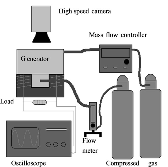
Figure 10. Arrangement of the power evaluation.
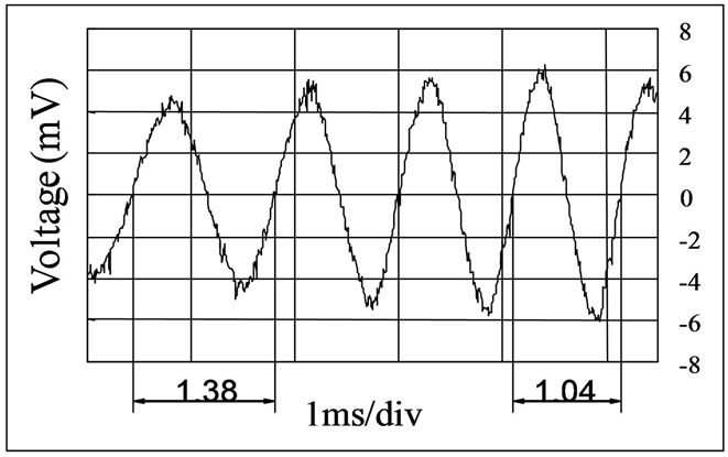
Figure 11. Output waveform of the monolithic type.
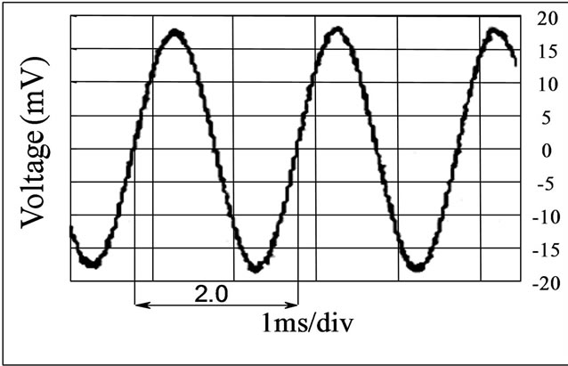
Figure12. Output waveform of winding wire type.
lation of the induced current and the generated break force. This relation is not simple because it is depend on the magnetic flux and the coil structure. In the case of the magnetic ceramics, the flux is concentrated in the narrow area. Therefore, it is possible to think the braking torque should be small.

Table 2. Comparison of the winding wire and the monolithic type.
5.2. Turbine Circulation
In the multilayer magnetic circuit type, it was observed that the time dependence of the rotational speed and the output voltage. The amplitude of the output voltage increases with the increase of the rotating speed. According to Faraday’s law of electromagnetic induction, the output voltage is proportional to the time derivative of the magnetic flux crossing the coil. The observed output voltage dependence is thought to follow this relation.
Also, the maximum rotational speed of 58,000 rpm was observed at 0.28 MPa. Even at the higher pressure, the rotational speed was decreased. In order to observe the circulation of the rotor, a glass top cover was prepared instead of the silicon rid. From the high speed camera observation, it was found that the rotor behaved shaky motion that the axis of the rotor was deviated from the center axis of the stator and changed the rotational speed. Figure 13 shows the two positions of the rotor at 0.28 MPa, the center and the deviated, respectively. In this air turbine, the restriction of the maximum speed seems to be due to this shaky motion. The higher pressure enhanced the shaky motion. And then the motion became unstable. Since the rotational speed is directly result in the output power, this motion has to be suppressed.
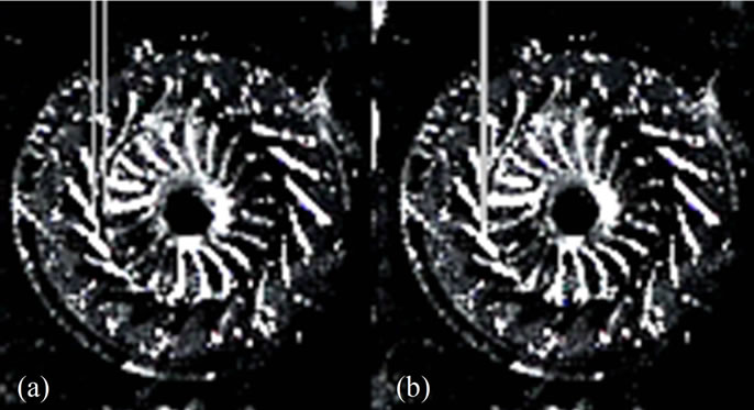
Figure 13. Two positions of the rotor observed by the high speed camera, (a) center and (b) deviated.
5.3. Power Evaluations
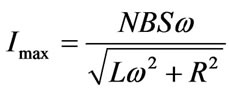
In this calculation model, it is assumed that all the magnetic flux passes through coil circuit. Therefore, major difference between the calculated value and the measured value is thought to be attributed to the flux leakage. The maximum current Imax is solved in the following Equation (1).
 (1)
(1)
Where the magnetic flux density is B, the surface area of the magnetization is S, the resistance is R, the inductance is L, turns of the coil is N and angle rate is ω. Assigning each value to formula, B = 1.5 × 10⁻¹ T, S = 0.87 mm2, R = 20 Ω, L = 6.25 μH, N = 18 turn, and ω = 2πf = 2π × 967 rad/s, the result of the maximum current 0.71 mA and the apparent power 10.1 μVA were calculated. In this calculation, 2π × 967 rad/s corresponding to the measured maximum rotational speed of 58000 rpm was used. The measured output power was 19% of the estimated power.
5.4. FEM Analysis
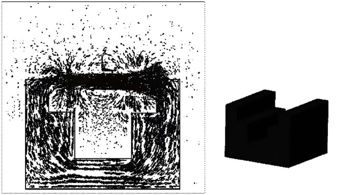
In order to discuss the reason of 19%. We consider the distribution of the magnetic flux. In the Equation (1), it is assumed that the all magnetic flux is passed through the magnetic materials. Figure 14 shows the analyzed results of the magnetic flux density distribution by using finite element method. It is found that a large number of magnetic flux outside the magnetic circuit existed around the part between the magnet bottom and the magnetic circuit. This flux leakage is thought to provide a significant influence on the obtained power. The calculated leakage of the flux was about 80%. It is corresponding to the measured result.
It is possible to suppress the leakage by reducing the gap between the magnet and the magnetic circuit. Figure 15 shows the FEM analysis on the narrow gap structure.
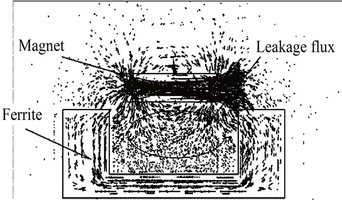
Figure 14. Analyzed results of the magnetic flux density distribution by finite element method.
 (a) (b)
Figure 15. Narrow gap structure for high output, (a) FEM analysis; (b) Schematic illustration.
From the view point of the magnetic leakage, the multilayer magnetic ceramic circuit has enough possibility to exceed the power density of the winding wire. Also, the multilayer magnetic ceramic circuit realizes the monolithic structure. Therefore, applying the multilayer magnetic ceramic circuit to the MEMS micro generator is quite effective.
6. Conclusion
The electromagnetic type MEMS micro power generator was fabricated in this study. The generator was composed of the MEMS air turbine and the magnetic circuit. The monolithic circuit by multilayer magnetic ceramic was proposed. The monolithic generator was compared to the simple winding wire type magnetic circuit. In the power density measurement, almost same output power density was extracted though the turn number of the winding wire type was more than that of monolithic type. Also the resistance of the conductor was quarter of the winding type. The maximum output voltage and the maximum power of the monolithic generator was 6.2 mV and 1.92 µVA respectively. The DC conductor resistance was 1.2 Ω. The energy density was 0.045 µVA/mm3. The appearance size of the monolithic type was 3.6, 3.4, 3.5 mm, length, width and height, respectively.
7. Acknowledgements
This research was supported by KAKENHI (22560254). Also, we used the facility of Research Center for Micro Functional Devices of Nihon University for the fabrication of the MEMS micro air turbine. The authors appreciate the support.
REFERENCES
- A. H. Epstein and S. D. Senturia, “Macro Power from Micro Machinery,” Science, vol. 276, No. 5316, 1997, p. 1211. doi:10.1126/science.276.5316.1211
- A. H. Epstein, “Millimeter-Scale MEMS Gas Turbine Engines,” Proceedings of ASME Turbo Expo 2003 International Joint Power Generation Conference, Atlanta, 16- 19 June 2003, pp. 669-696. doi:10.1115/GT2003-38866
- A. Holmes, G. Hong and K. Pullen, “Axial-Flux Permanent Magnet Machines for Micropower Generation,” Journal of Microelectromechanical Systems, Vol. 14, No. 1, 2005, pp. 54-62. doi:10.1109/JMEMS.2004.839016
- S. Das, D. P. Arnold, I. Zana, J. W. Park, J. H. Lang and M. G. Allen, “Multi-Watt Electric-Power from a Microfabricated Permanent-Magnet Generator,” 18th IEEE International Conference on Micro Electro Mechanical Systems, 30 January-3 February 2005, pp. 287-290. doi:10.1109/MEMSYS.2005.1453923
- H. Raisigel, O. Cugat and J. Delamare, “Permanent Magnet Planar Micro-Generators,” Sensors and Actuators A: Physical, Vol. 130-131, 2006, pp. 438-444. doi:10.1016/j.sna.2005.10.007
- D. P. Arnold, F. Herrault, I. Zana. P. Galle, J.-W. Park, S. Das, J. H. Lang and M. G. Allen, “Design optimization of an 8 W, microscale, Axial-Flux, Permanent-Magnet Generator,” Journal of Micromechanics and Microengineering, vol. 16, no. 9, 2006, pp. S290-S296. doi:10.1088/0960-1317/16/9/S17
- C. Pan and T. Wu, “Development of a Rotary Electromagnetic Microgenerator,” Journal of Micromechanics and Microengineering, Vol. 17, No. 1, 2007, pp. 120-128. doi:10.1088/0960-1317/17/1/016
- B. C. Yen, F. Herrault, K. J. Hillman, M. G. Allen, F. F. Ehrich, S. Jacobson, C.-H. Ji, J. H. Lang, H. Li, Z. S. Spakovszky and D. R. Veazie, “Characterization of A Fully-Integrated Permanent-Magnet Turbine Generator,” Proceedings of PowerMEMS, Sendai, 9-12 November 2008, pp. 121-124.
- F. Herrault, C.-H. Ji and M. G. Allen, “Ultraminiaturized, High-Speed, Permanent-Magnet Generators for MilliwattLevel Power Generation,” Journal of Microelectromechanical Systems, Vol. 17, No. 6, 2008, pp. 1376-1387. doi:10.1109/JMEMS.2008.2004854
- C. Pan and Y. Chen, “Application of Low Temperature Co-Fire Ceramic on In-Plane Micro-Generator,” Sensors and Actuators A: Physical, Vol. 144, No. 1, 2008, pp. 144- 153. doi:10.1016/j.sna.2007.12.008
- F. Herrault, B. C. Yen, C.-H. Ji, Z. S. Spakovszky J. H. Lang and M. G. Allen, “Fabrication and Performance of Silicon-Embedded Permanent-Magnet Microgenerators,” Journal of Microelectromechanical Systems, vol. 19, no. 1, 2010, pp. 4-13. doi:10.1109/JMEMS.2009.2036583
- R. Cordero, A. Rivera, M. Neuman, R. Warrington and E. Romero, “Micro-Rotational Electromagnetic Generator for High Speed Applications,” 25th International Conference on Micro Electro Mechanical Systems, Paris, 29 January-2 February 2012, pp. 287-290. doi:10.1109/MEMSYS.2012.6170385
- A. J. Blodgett, “A Multilayer Ceramic Multi-Chip Module,” IEEE Transactions on Components, Hybrids, and Manufacturing Technology, vol. 3, No. 4, 1980, pp. 634- 637. doi:10.1109/TCHMT.1980.1135663