Optics and Photonics Journal
Vol.4 No.7(2014), Article
ID:48138,5
pages
DOI:10.4236/opj.2014.47019
Erbium Doped Fiber Laser and Amplifier
Belloui Bouzid
Electrical Engineering Department, Affiliated Colleges Hafr Al-Batin, King Fahd University of Petroleum and Minerals (KFUPM), Riyadh, KSA
Email: belloui@kfupm.edu.sa
Copyright © 2014 by author and Scientific Research Publishing Inc.
This work is licensed under the Creative Commons Attribution International License (CC BY).
http://creativecommons.org/licenses/by/4.0/


Received 26 March 2014; revised 24 April 2014; accepted 21 May 2014
ABSTRACT
In this paper, new configuration is proposed, investigated and analyzed. Fiber laser and fiber amplifier are merged in one configuration which called Erbium Doped Fiber Laser and Amplifier (EDFLA) or integrating EDFL and EDFA in one design. The configuration has three main outputs; one for laser, second for amplifier and the third it can be used for on/off output. A surprising phenomenon was remarked during the operation of this configuration. The amplification is abolished during the lasing state and appeared again if the lasing is stopped or the switch is off. The difference between outputs with the lasing and without lasing has 30 dB EDFA gain value; it is a good sign that this optical configuration can be used as an on/off integrated optical device for fiber laser.
Keywords:Erbium Doped Fiber Amplifier, Erbium Doped Fiber Laser, Lasing, Amplification

1. Introduction
Laser and its derivatives are playing crucial roles in a wide domain of science and technology, due to their advantages and great efficiencies in army [1] [2] , medical [2] and communications [3] . The laser and amplifier field are very broad and innovative for the coming holography and optical computing generations.
Fiber laser and fiber amplifier are worth to play an important role in the coming new revolution of science due to their hands on experimental manipulations and to their clear experimental structure for any beginner. It is an easy task to deal with confined laser in fibers and replace the different components for both fiber laser and fiber amplifier configuration in order to characterize and analyze its outputs.
It is worth to prepare the physical engineers to analyze and study both the theory and experiment of lasers. The analysis of the experimental results based on theoretical explanations is the only way to clarify the deep complexity of lasers and amplifiers. Then the simulation is to simulate these results in an easy method for any beginner in lasers and amplifiers field.
The real and original discovery of lasing phenomenon starts with the lasing theory [4] , discovery of laser by Maiman [5] and the amplification of Snitzer [6] . Numerous books and papers have been published to clarify and explain the laser theory and its complex behavior at the atomic scale. Fiber laser at the late eighteenth was discovered [7] to show that EDFL and EDFA can be used as appropriate tools for communication at lower absorption and low power.
Fiber laser and fiber amplifier have their numerous components for each design with the effect of each parameters and parts on the output. By simplification of the role of each component and its formula, the theoretical dilemma can be solved. Nearly all the shown formulas are related to a general rule but not to specific state and component with a detailed theoretical background. Giving an example in fiber ring laser, any changes of the filter position in the ring can affect the output result. The question that needs theoretical answers is: How an agreement can be existed between the theory and the experiment for the different positions of the filter in the ring laser?
All the published papers studied separately the fiber laser and fiber amplifier. In this paper, a new and sophisticated design is discovered trying to merge both fiber laser and fiber amplifier in one configuration and use the same pump for both outputs. Unfortunately or fortunately, we have discovered that at the lasing time there is no amplification or the signal travels the erbium doped fiber core without any amplification or absorption. But in the case where there is no lasing, the amplification is occurred.
2. Experimental Design and Discussion of Results
A 6 m EDF length was used in this experiment with 1000 ppm of Erbium ions concentration. The measured loss was of 3.5 dB absorption between the input and output amplifier, and 6 dB inside the laser ring. The constructed configuration is shown in Figure 1. The input signal power is generated from tunable laser source (TLS) it travels through CIR1 from Port 1 to Port 2 it will be amplified in the EDF then travels through the WDM and CIR2 from Port 2 to Port 3 where an optical spectrum analyzer (OSA1) is connected to Port 3 to characterize the signal. The WDM is to multiplex the 980 nm pump power and the input signal power at different wavelength in a counter pumping configuration.
In the lasing case, a laser ring is constructed by connecting Port 1 CIR2 with Port 3 of the CIR2. The laser generated in the EDF, under the effect of 980 nm pump power, travels from Port 2 to Port 3 of CIR1, then it will be filtered via the TBF. After the TBF an on/off switch is positioned to choose between laser and amplifier. The coupler is to select the output ratio. The remained portion from the coupler travels to Port 1 then to Port 2 of the CIR2 to complete the turn of the laser condition in the ring.
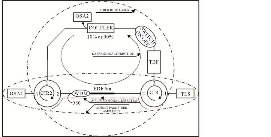
Figure 1. Experimental configuration of EDFLA.
As it was mentioned the configuration has three main outputs one is for amplification the second is for lasing and the third is for the on/off optical devices. Figure 2 shows the three bands of the used EDF amplification. S, C and L bands can be used for both lasing and amplifications. Figure 2 is shown based on the use of C + L and S + C reflectors. The graph shows also that the 1650 nm - 1420 nm = 230 nm Amplified Spontaneous Emission (ASE) can be used for amplification and lasing if the configuration is designed rightly and the pumping is used efficiently. The figure also shows that a high concentration of erbium doped inside the fiber core will broaden the lasing and amplification spectra.
Figure 3 shows the gain of 30 dB value at −45 dBm input signal power from the TLS with 100 mW pump power. The main result achieved with this new configuration is the difference between two amplified signal with and without lasing. If the switch is off, it means no lasing, a 30 dB gain was recorded but by switching the lasing on the gain value becomes 1 dB, no amplification and no absorption it seems the fiber becomes transparent for the 1550 nm input signal power at different values.
The OSA1 is recording the amplification and OSA2 is recording the laser. Figure 4 is illustrated using OSA1 at 1550 nm input signal power of −45 dBm with different pumping power at 10 mW increment. The gain amplification without lasing is around 30 dB but when the lasing is started the gain becomes 1 dB, with 30 dB difference between the on and off of lasing. This new result is considered to be new at two levels the first when the
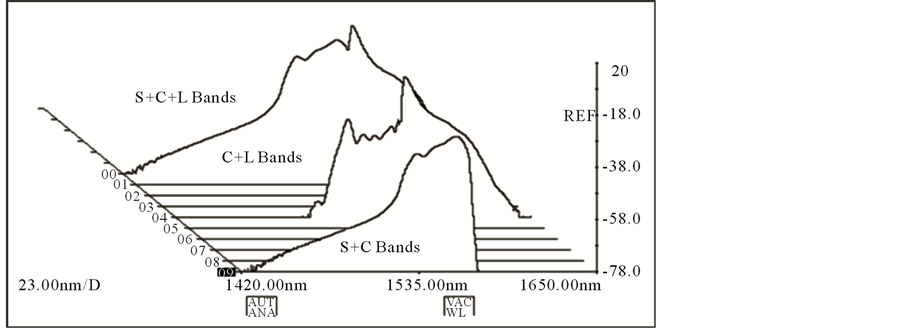
Figure 2. ASE spectra of the used EDF at 100 mW pump power.
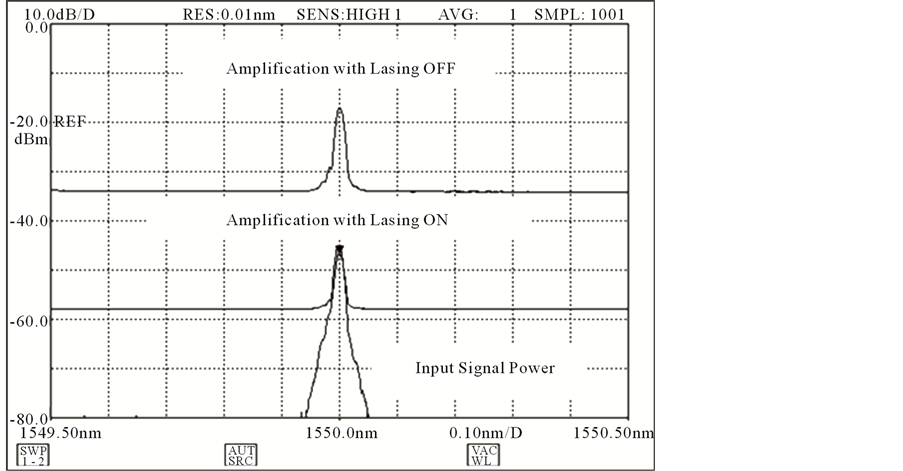
Figure 3. Amplification spectra recorded in OSA1 with laser OFF and ON.
configuration is used at the digital optical devices and the second is the elimination of the amplification if the lasing is on, it means also that the erbium excitation woks only in one side either amplification or lasing.
It is clearly remarked in Figure 4, the vanishing of ASE after we turn on the laser operation. It appeared that both forward and backward ASE’s are shifted to the generation of laser power. This figure shows an astonishing phenomena and it needs more explanation at the backward ASE abolishment level and at the pump power less than threshold limit level. The phenomenon of abolishment of the amplification during the laser shows that the energy of Erbium ions can be used only for one operation either for the laser or amplification. In this configuration, the lasing holds the energy and keeps the amplification at the value gain one dB, where the erbium ions are unable to absorb even the signal coming from the TLS. It is transparency EDF.
The 3D tuning range graph at 10 nm increments using the TBF of the ring laser was recorded using the OSA2 in Figure 5. It is evident the existence of the wide tuning range of the laser at high concentration erbium ions and short EDF length. A 90 nm tuning range is achieved using this configuration. Due to high concentration of ions of erbium in the fiber core a wide and stable lasing is recorded between 1521.66 nm and 1612.52 nm.
Figure 5 is recorded by tuning the TBF and recording the output laser power in OSA2. It was remarked that there is no ASE because in this case the TBF was positioned before the output coupler.
3. Conclusion
A new design was conceived and implemented to generate laser and amplifier in one single configuration. A
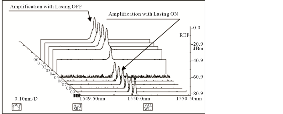
Figure 4. Amplification spectra recorded in OSA1 with laser OFF and ON.
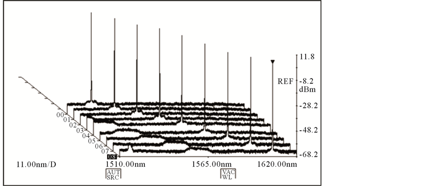
Figure 5. 3D tuning range of fiber ring laser.
noticeable effect of laser phenomena was recorded during the lasing and amplification. The EDF changes inversely its behavior of amplification during the lasing state, no amplification no absorption at the lasing state of the injected 1550 nm input signal power. It seems that the EDF is converted to transparent material during the lasing operation. If the laser is off, there is amplification with 30 dB gain at −45 dBm input signal power.
Acknowledgements
The author wishes to acknowledge MMU (Malaysia), KACST and ACHB/KFUPM (Saudi Arabia) for their support in providing the various facilities utilized in the presentation of this work.
References
- Curran, G.L. and Engelken, D.J. (1990) Ring Laser Gyro Applications for Tactical Missiles: The Army TACMS Solution. Position Location and Navigation Symposium, IEEE PLANS ‘90, IEEE Digital Object Identifier, 543-548.
- Canales, P., Meshal, A., Ricklin, J. and Vallestero, N. (1990) Bandwidth Enhancements for the Army Network through Laser. Aerospace Conference. 2004 IEEE Volume: 3 Digital Object Identifier.
- Alvarez-Chavez, J.A., Cruz, M., Martinez-Rios, A.L., Torres-Gomez, I. and Martinez-Pinon, F. (2006) High Power Er3-/Yb3+-Doped Fiber Laser Suitable for Medical Applications. Electronics and Photonics. Multiconference on Digital Object Identifier, 279-281.
- Schawlow, A.L. and Townes, C.H. (1958) Infrared and Optical Maser. Physical Review, 112, 1940-1949.http://dx.doi.org/10.1103/PhysRev.112.1940
- Maiman, T.H. (1960) Stimulated Optical Radiation in Ruby. Nature, 187, 493-496.http://dx.doi.org/10.1038/187493a0
- Koester, C.J. and Snitzer, E. (1964) Amplification in a Fiber Laser. Applied Optics, 3, 1182.http://dx.doi.org/10.1364/AO.3.001182
- Mears, R.J. (1987) Optical Fiber Lasers and Amplifiers. Ph.D. Thesis, University of Southampton, Southampton.