Optics and Photonics Journal
Vol.3 No.8(2013), Article ID:41595,6 pages DOI:10.4236/opj.2013.38059
Thermal Stress Monitoring on Piston Rings by Real Time Holographic Interferometry
1Department of Physics, Kenyatta University, Nairobi, Kenya
2Department of Physics, Jomo Kenyatta University of Agriculture & Technology, Nairobi, Kenya
Email: *grurimo@gmail.com
Copyright © 2013 Stephen N. Maina et al. This is an open access article distributed under the Creative Commons Attribution License, which permits unrestricted use, distribution, and reproduction in any medium, provided the original work is properly cited. In accordance of the Creative Commons Attribution License all Copyrights © 2013 are reserved for SCIRP and the owner of the intellectual property Stephen N. Maina et al. All Copyright © 2013 are guarded by law and by SCIRP as a guardian.
Received October 1, 2013; revised November 5, 2013; accepted November 28, 2013
Keywords: Interferogram; Hologram; Aberration; Piston Ring; Laser Beam
ABSTRACT
In this paper, real time holographic Interferometry (RTHI) technique was used to monitor the thermal stress on the piston rings. The piston rings holograms were recorded and the holographic plate replaced on the holder after development. The piston ring was subjected to thermal stress as it was illuminated by Laser beam acting as the object beam. This process led to generation of interferograms which were captured by a CCD camera at different temperatures. The captured interferograms were analyzed using atmosfringe version 3.3 software. From the analysis, the peak to valley (P-V) aberrations measured for each of the piston ring varied for the same temperature value. The P-V aberrations ranging from 0.0128λ to 1.2989λ were obtained. From this result, it was evident that the three rings on the piston had different unique structural characteristics due to their function.
1. Introduction
Holography is a technique of recording the interference pattern between an object wavefront and a reference wavefront on a photosensitive medium [1]. The unique aspect of the technique is to generate original wavefront by reconstruction. Apart from being an imaging technique that has received much attention since its inception by Dennis Gabor in 1948 [2,3], holography has also been employed in other fields.
One of the major applications of holography is holographic Interferometry which was developed in the late 1960s by Stetson and Powell [4,5]. Holographic Interferometry involves interference of two coherent wavefronts reflected from two different states of the object [6, 7]. Using the technique, the quantities of interest such as displacement, deformation, stress and body shape are encoded inform of interferograms [8,9]. The technique involves three major processes: hologram recording, hologram developing and reconstruction. These are the major principles of holography [10]. The hologram stores the complicated wave pattern which can be retrieved at a later time [11,12]. In order to record a hologram, a known reference wave is combined with an object wave (a wave diffracted from the object) onto a holographic plate. After recording, the hologram is developed using chemicals before reconstruction [12,13].
Holographic Interferometry has been widely used in detecting deformities on opaque surfaces or refractive index variation in a transparent media [14,15]. Unlike other non-destructive testing methods, holographic Interferometry is able to extract full field information of a body as opposed to point inspection. Using the technique, it is possible to resolve the optical path change up to one hundredth of the light source wavelength [16,17]. This implies that the technique yields extremely accurate measurement of minute surface deformation hence very advantageous [18].
More advantages of using Holographic Interferometry as an inspection technique include: measuring strain regardless of the direction. The variation of strain over the entire sample can be obtained with ease as there is no physical contact with the sample. The sample preparation is not required, and the experimental set up is simple to implement.
In order to understand the thermal mechanical behavior of the piston rings, an accurate measurement method is essential. In this paper, a non-destructive testing method based on real time holographic Interferometry is presented. The technique was used to investigate thermal stress subjected on the piston rings surface. This was done by analyzing the generated interferograms at different temperatures.
2. Experimental Set-Up
2.1. Recording of the Hologram
The recording of the holograms was carried out in a darkroom. This was done at a time when all the light sources were blocked, the movements within the room minimized and temperature equilibrium attained. The piston ring was placed in such a way that beam illumination was maxima and equalized at all parts of the piston ring whose hologram was to be recorded. To record the holograms PFG-01 holographic plates of dimensions 102 mm × 127 mm were used. The holographic plate was placed on a mount when the entire light source had been blocked with the emulsion side facing the direction of the beam source. The hologram recording set up used is as illustrated in Figure 1.
Light from a 35 mW linearly polarised Helium Neon Laser of wavelength 632.8 nm was used. The light from the Laser was spatially filtered using the microscope objective lens of ×10 magnification and a 30 µm diameter pinhole located at the microscope objective focal point. Using a beam splitter the Laser beam was split to give two arms (object beam and reference beam). The object beam was the beam transmitted through the Beam Splitter and incident on the piston ring whose hologram was to be recorded. This beam was reflected to the holographic plate by the piston ring as depicted in Figure 1.
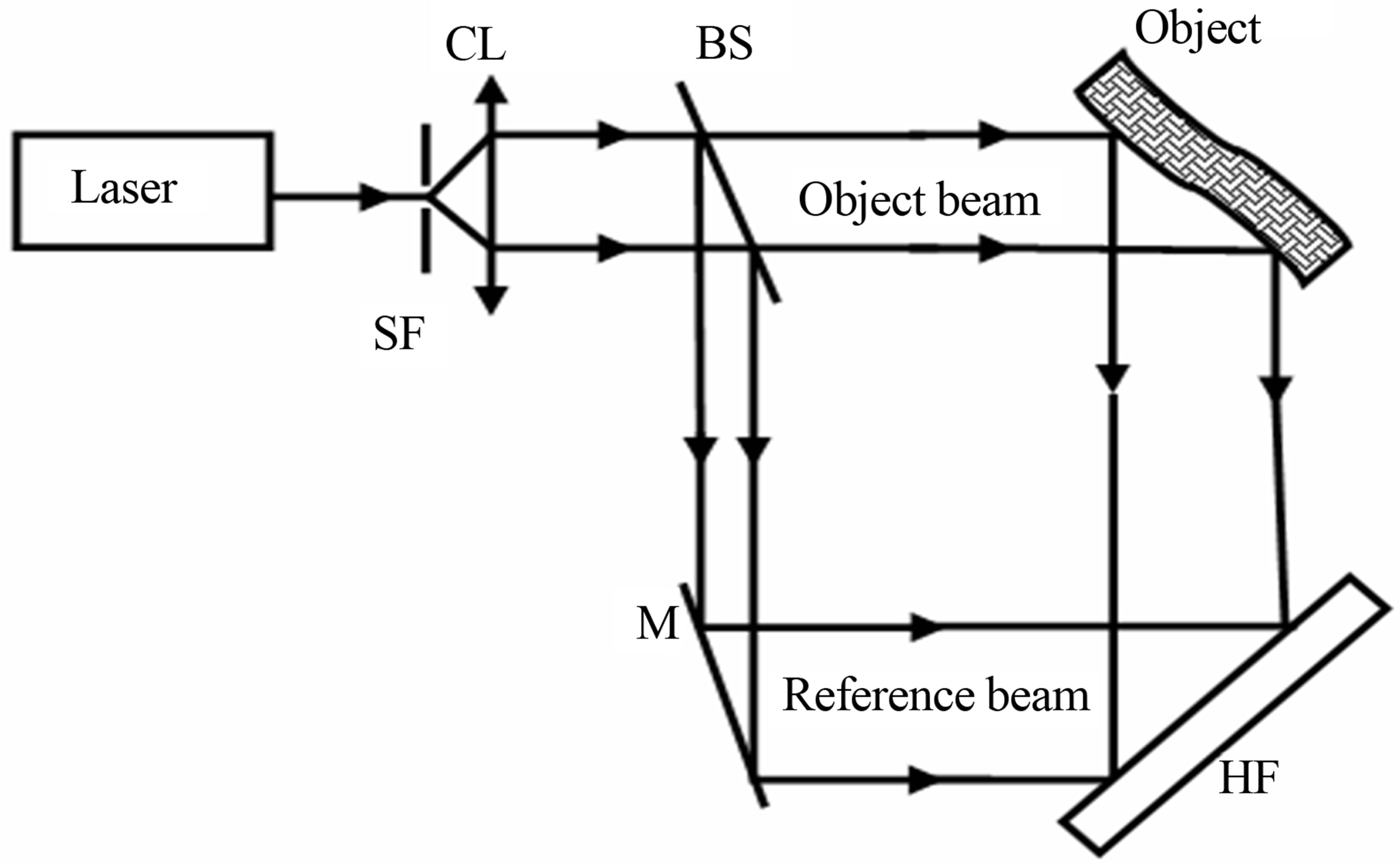
Figure 1. Schematic illustration of holographic recording set-up. SF is the spatial filter, CL is the collimating lens, BS is the beam splitter, HF is the holographic plate and M is reflecting mirror.
The beam reflected by the beam splitter (the reference beam) was incident on the holographic plate. The setup was allowed to stabilize for about two minutes before exposing the holographic plate. The stability of the Laser was ensured by use of a spectrum analyzer.
To record the hologram, the two beams were superimposed on the holographic plate for 20 seconds. After the holographic plates were exposed, they were ready for processing using developing chemicals. The chemical composition of the developer and bleaching solutions used are as shown in Tables 1 and 2 respectively.
The developing solution was prepared by mixing equal volumes of part A and B before exposing the holographic plate. The mixture was stirred to obtain a homogeneous developing solution. The exposed holographic plate was immersed into the developing solution with the emulsion side facing upwards for 120 seconds and swirled in the solution during developing period. It was rinsed for 180 seconds and later dipped into a bleaching solution for 120 seconds. After bleaching the holographic plate was dipped in photo flow solution for 30 seconds. The holographic plate was placed in an upright position for drying after processing.
2.2. Piston Rings Thermal Stress Measurement
To monitor the effect of thermal stress on the piston rings, three new piston rings of the same piston were used. The set-up used to monitor thermal stress is as shown in Figure 2. First the object holograms for each piston ring were recorded, processed and dried as earlier discussed in section 2.1. The dry processed holographic plate was inserted on the holographic plate holder and replayed using the object and reference beams. The interferograms generated were captured by a CCD camera of pixel resolution of 1024 × 768 and used as the reference interferogram. Caution was observed to avoid displacement of any of the optical component and the piston ring in ref-
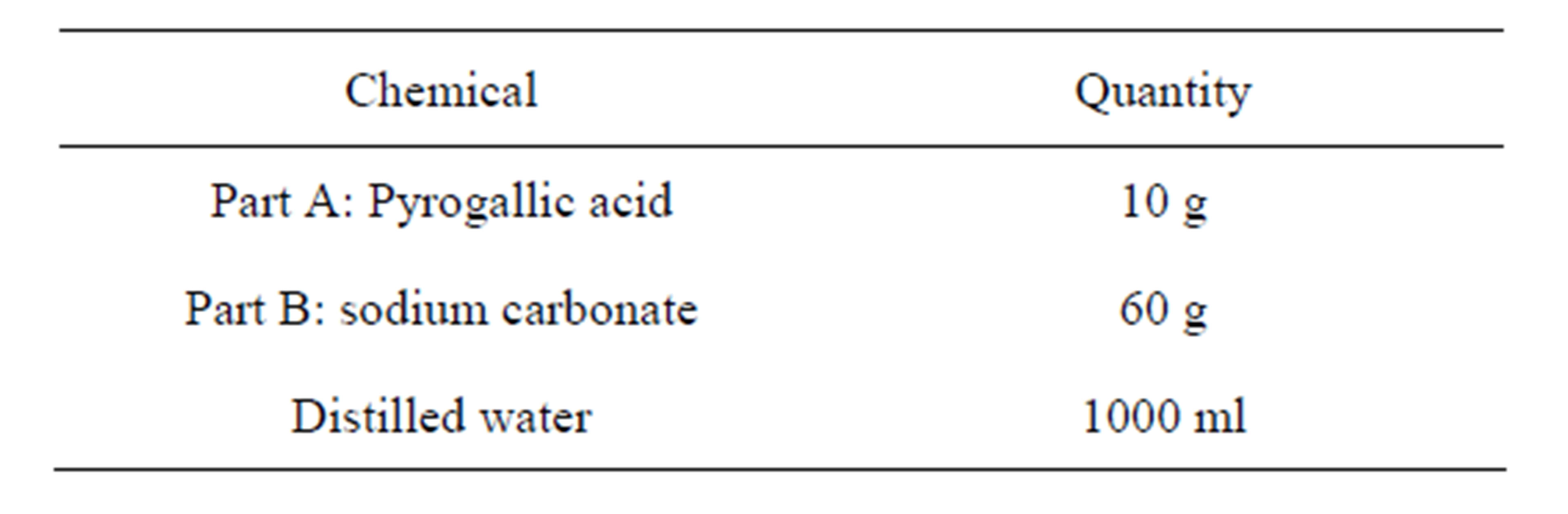
Table 1. Developer chemical composition.
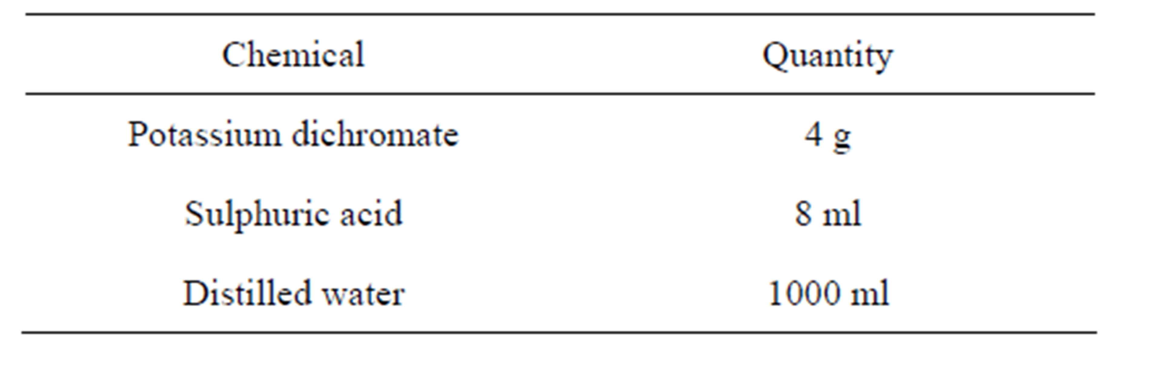
Table 2. Bleaching solution composition.
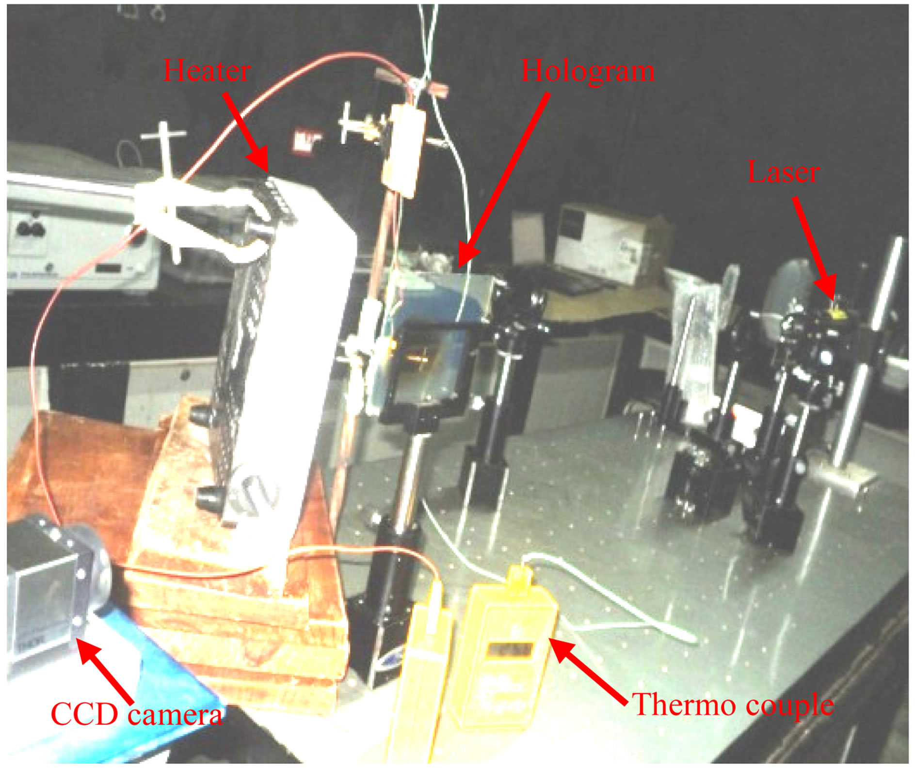
Figure 2. Real time holographic interferometric set up. The developed plate was replaced on the holder and the object subjected to heating. Using a CCD camera the generated interferograms were captured for analysis.
erence to their initial positions during hologram recording. The heating device was introduced behind the piston ring and the set-up allowed to stabilize as the movements within the room restricted before the heating device was switched on. To measure the temperature changes, two thermo couples were used placed equidistant from each other to ensure uniform temperature distribution.
On heating the piston ring as the developed holographic plate was illuminated by reference and object beams in the same orientation as during hologram recording, interferograms were generated. The generated interferograms were captured at temperature intervals of 5˚C. This was done for each of the three piston rings until a temperature of 100˚C was attained. To determine the effect of thermal stress on the piston rings analysis of the interferograms was done using Atmosfringe version 3.3 software.
3. Results and Discussion
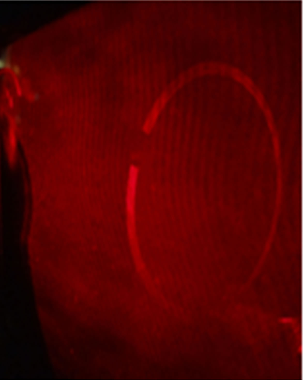
Exposing the holographic plate to the Laser beam causes a photochemical reaction that encodes information onto the holographic plate carried by the beam. To access the information, the development of the exposed plate was carried out. After processing of the exposed plate, it was inserted on the holographic plate holder and replayed. This was done by illuminating the processed holographic plate using reference beam. The reconstruction process affirmed the presence of successfully recorded hologram of the piston ring. The holographic images of the piston ring were captured using a 16.2 MegapixelsKodak digital camera. The photographs of the hologram images are as shown in Figures 3(a)-(c).
The three piston rings used in the work differed as they were subjected to thermal stress. This was exhibited by their respective interferograms as temperature varied. The interferograms are the result of the interference between the reconstructed object beam and the new object beam carrying information on thermal stress. In comparison with piston ring 1 and 3, piston ring 2 interferograms were stable at low temperatures though at higher temperatures they were adversely affected.
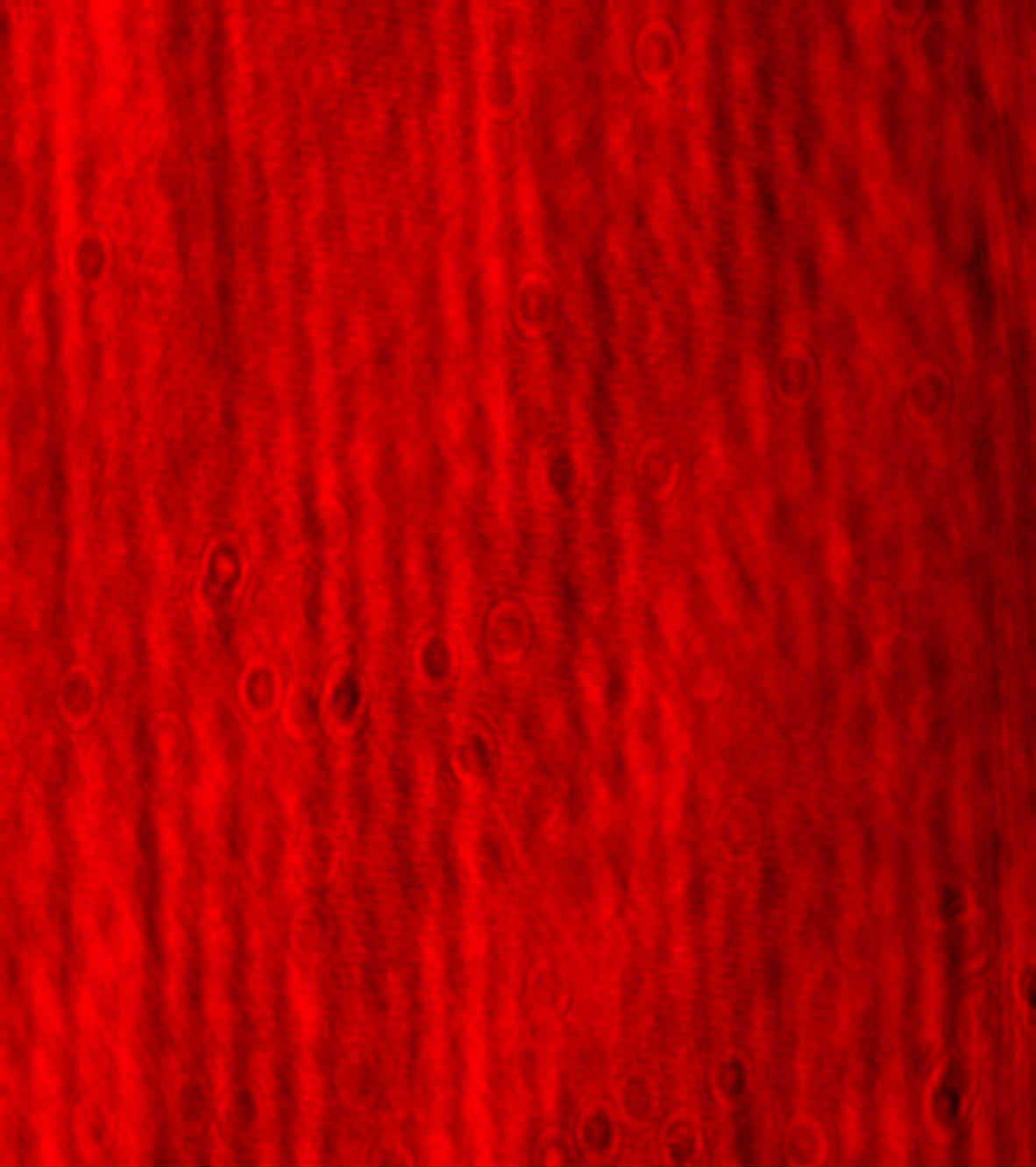
As piston ring 2 was subjected to thermal stress, a unique behavior of interferograms was observed. It was noticed that at low thermal stress (temperatures) the interference fringes were linear but from temperature of 35˚C and above the interferograms were characterized by geometrical variation in reference to interferograms recorded before the piston ring was subjected to thermal stress. These variations were more visible to the sense of sight at temperatures of 25˚C, 35˚C and 100˚C as shown in Figures 4(a)-(c).
The geometrical variations were characterized by bending and compression of the interferograms. The bending of the interferograms is due to change in fringe direction of some fringes as the piston ring was subjected to thermal stress. The compression of the interference fringes was depicted by an increase in optical fringe densities where more fringes occupy a unit length than before. This also affected visibility of the interferograms
 (a)
(a)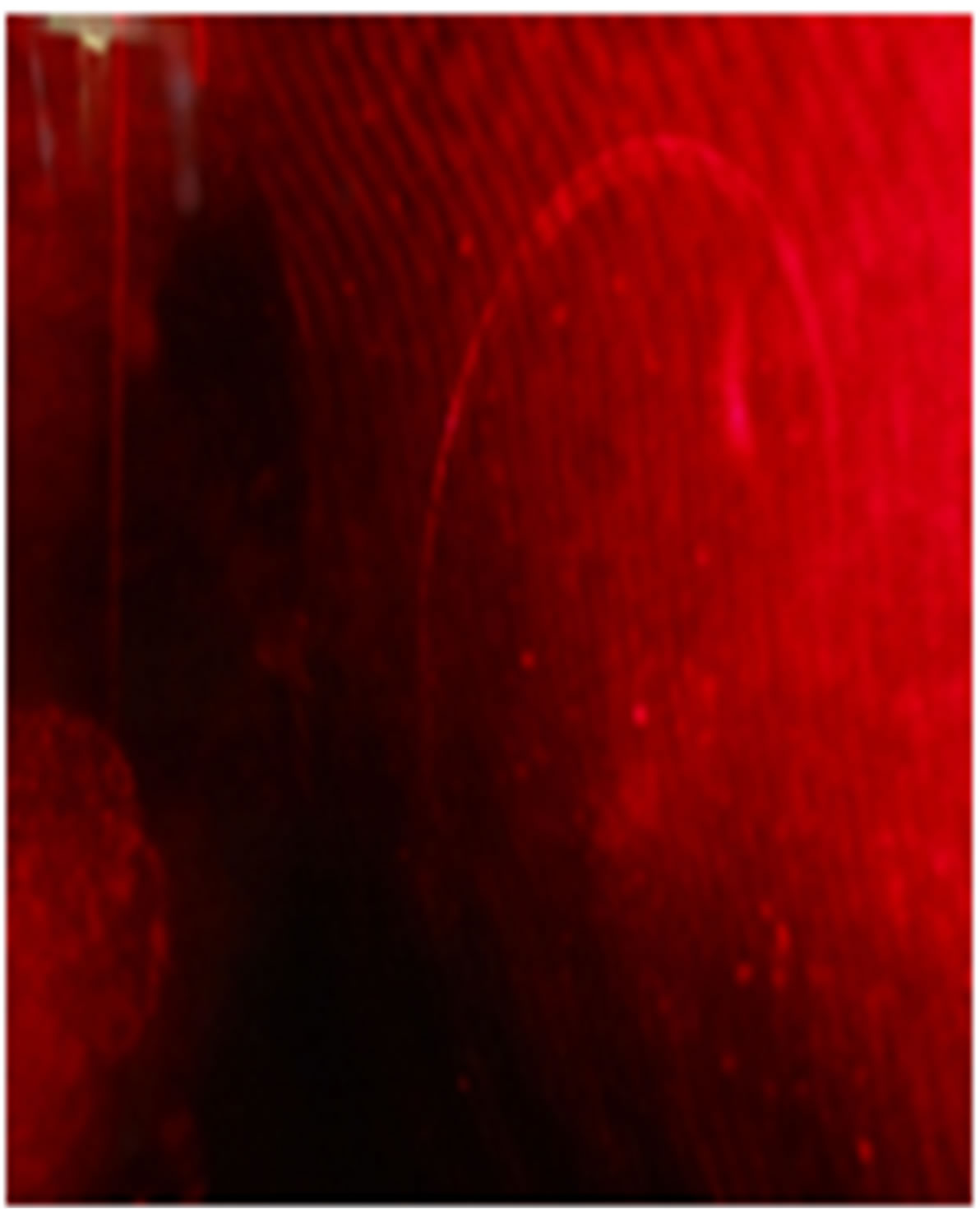 (b)
(b)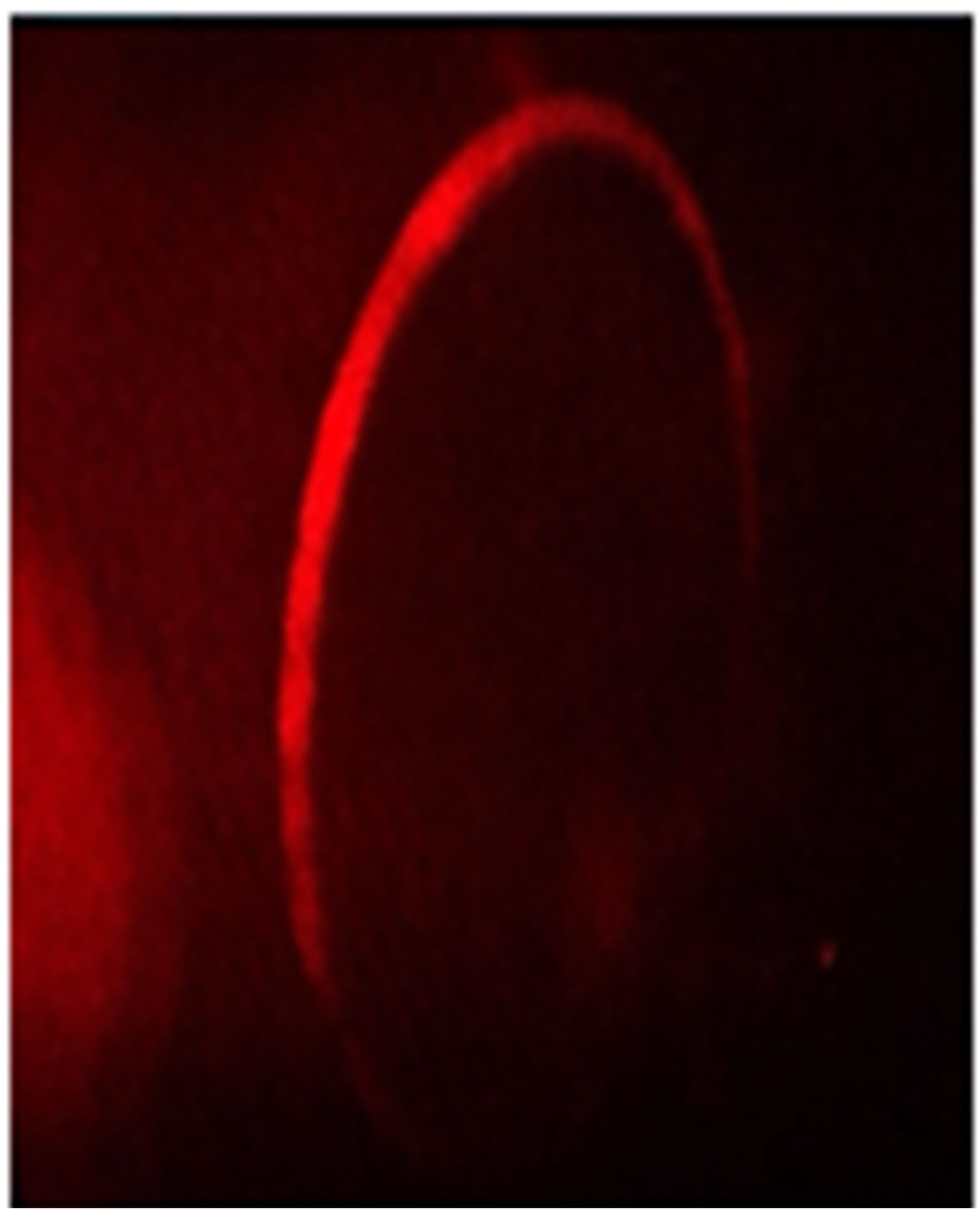 (c)
(c)
Figure 3. Photographic images of: (a) A hologram of piston ring 1; (b) A hologram of piston ring 2; (c) A hologram of piston ring 3.
 (a)
(a) (b)
(b)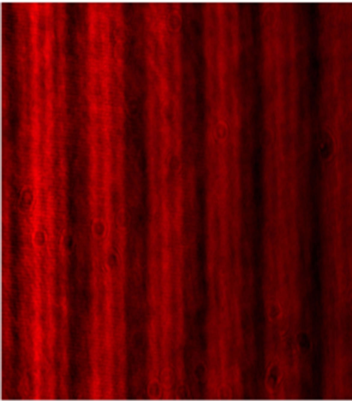 (c)
(c)
Figure 4. Sample interferograms captured by CCD for piston ring 2. The interferograms were characterized by geometrical variation as temperature increased. (a) The interference fringes are linear at 25˚C; (b) The interference fringes are curved at 35˚C; (c) The interference fringes appear compressed at 100˚C.
without the aid of a CCD camera due to resolution limitation of the human eyes as a result of change in spatial frequency of the fringes.
All the experimentally recorded interferograms were quantitatively analyzed using Atmosfringe version 3.3 from Astro-physics. The software is a powerful interferogram analyzer since it is capable of making measurements from the fringes such as aberrations, wavefront map, wavefront surface, modulation transfer function, point spread function among others. Using the software, quantitative measurements were done on the interferograms.
To analyze the interferograms captured using the CCD, they were loaded into the Atmosfringesoftware. Three points whose co-ordinates were given as follows: point 1: (231, 11), point 2: (13,251) and point 3: (502, 277) on each interferogram aperture were selected for analysis.
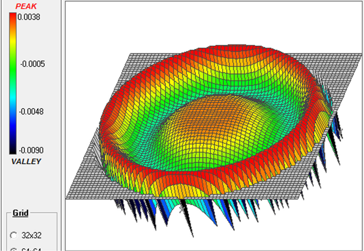
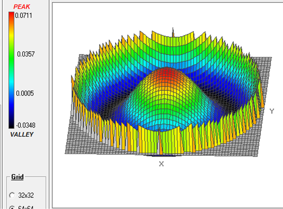
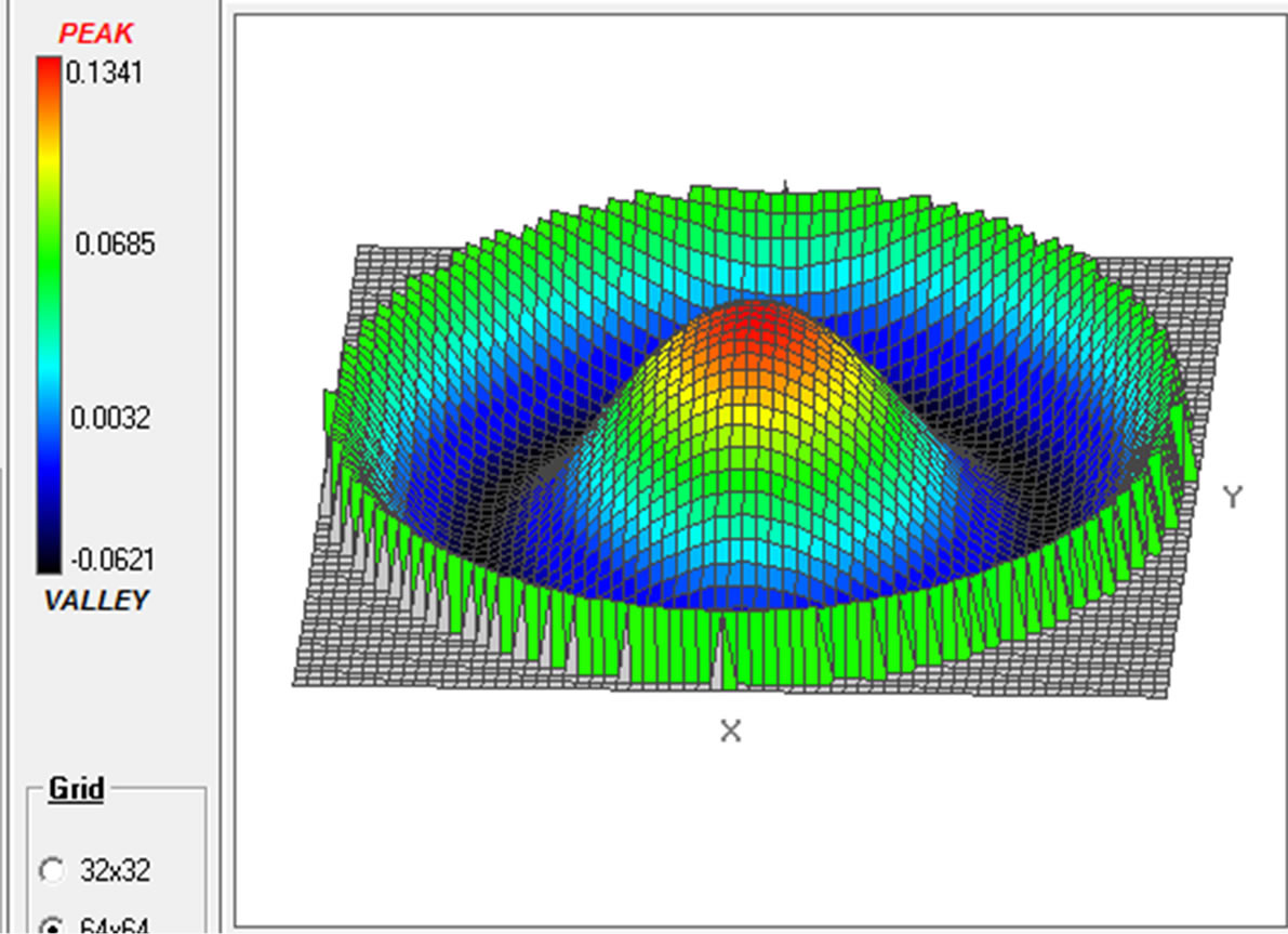
The Atmosfringe software extracted data from the interferogram. The extracted interferogram data was used in determination of the wavefronts aberration as different interferograms were loaded into the software. The peak to valley (P-V) aberrations, RMS,Strehl ratio and RMS fit errors (quality of fit) on the interferograms were obtained. The analysis revealed a variation of aberrations with change in temperature. The variations in aberrations were nonlinear as same temperature change resulted to different aberration values for each of the piston ring under test.3D graphical analysis of the inteferograms obtained for sampled temperature of 25˚C, 40˚C and 60˚C on the piston rings are displayed in the Figures 5(A)-(C).
The analysis clearly displays in Figure 5 of variation in peaks and valleys of the interferogram as temperature varied. The variations were characterised by shifts in
 (a)
(a) 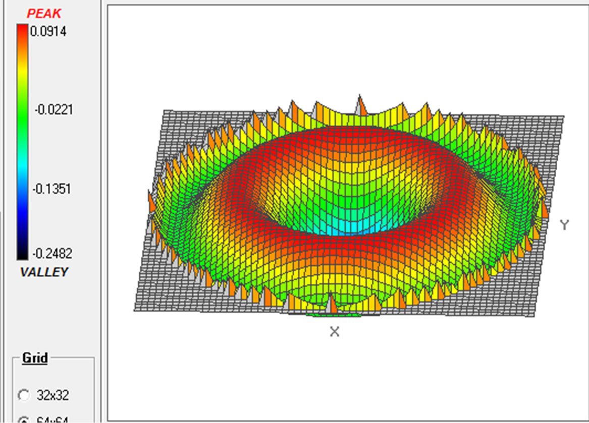 (a)
(a) 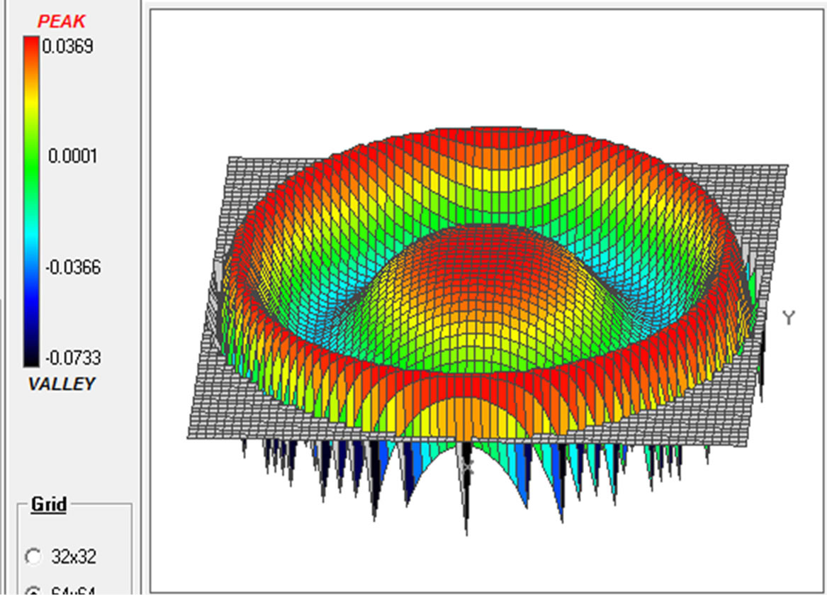 (a)
(a)
 (b)
(b) 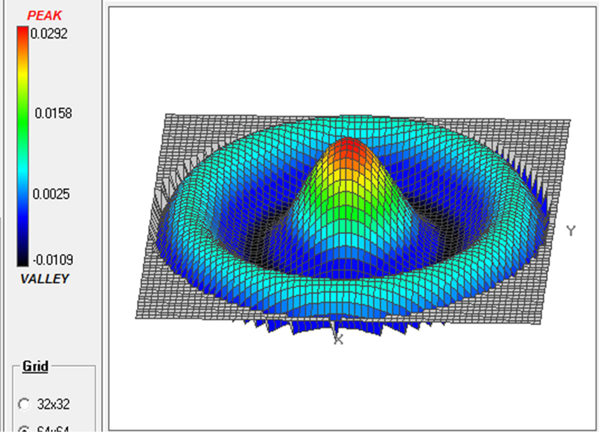 (b)
(b) 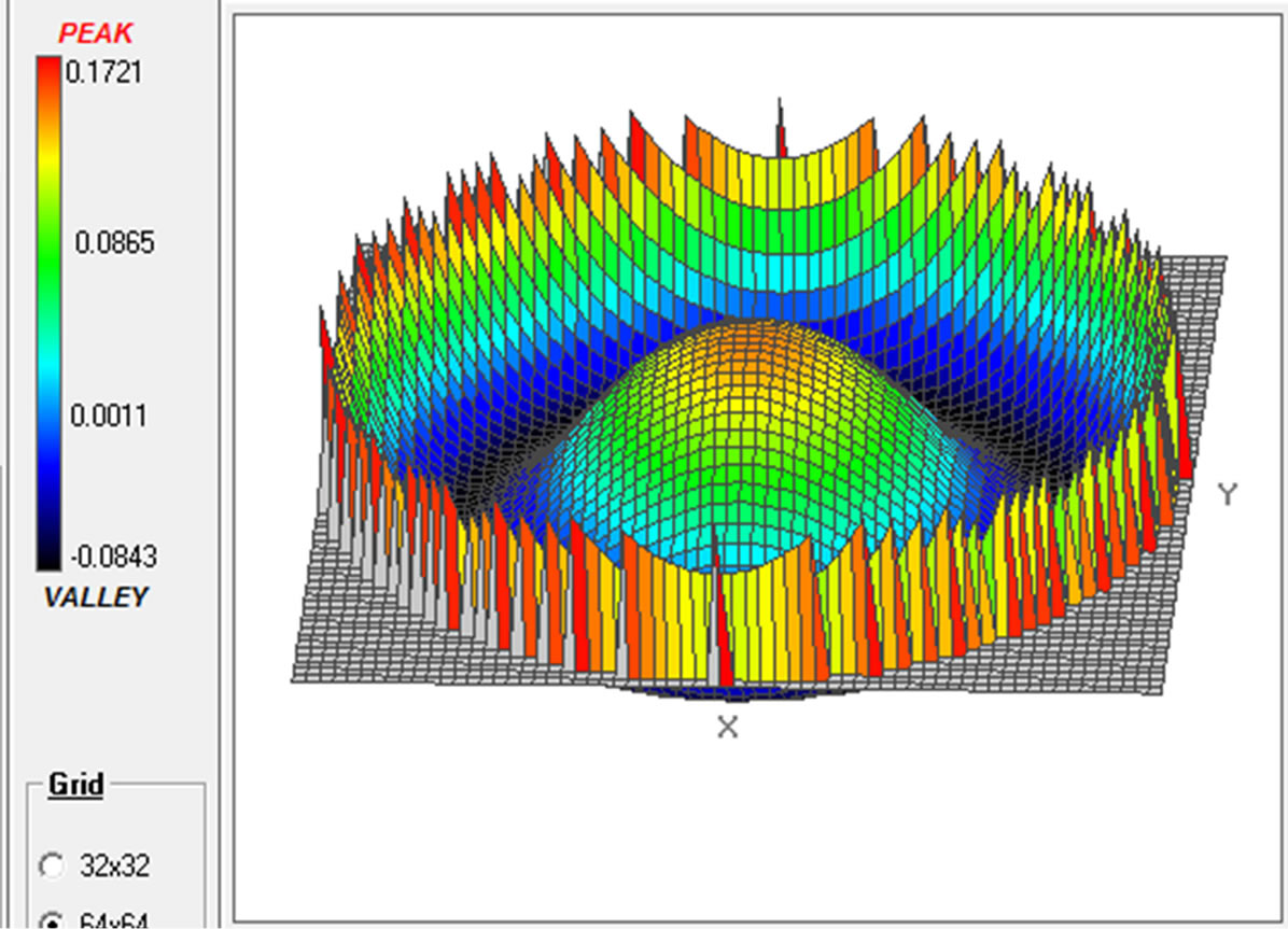 (b)
(b)
 (c)
(c) 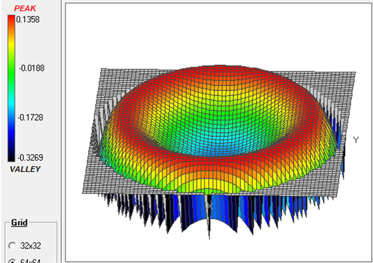 (c)
(c) 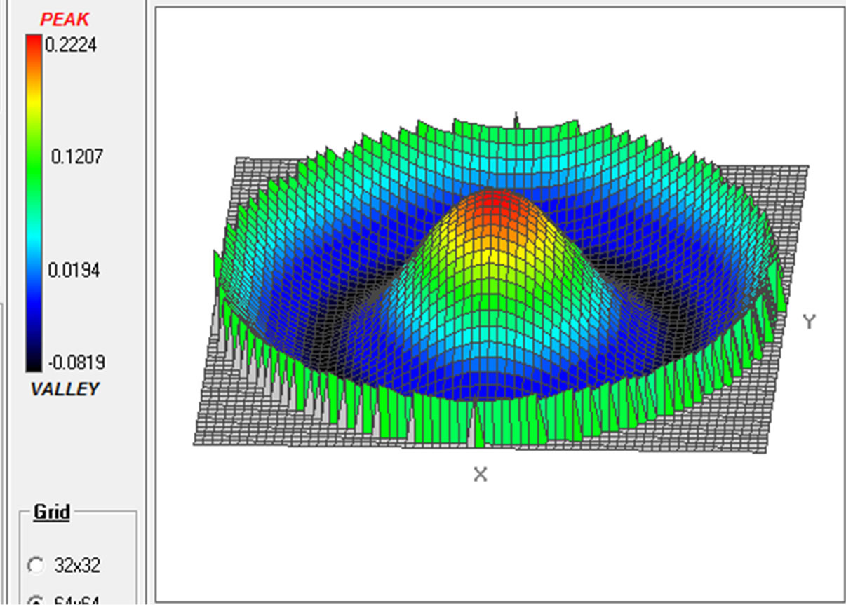 (c)
(c)
A B C
Figure 5. The profiles illustrate the P-V aberrations of the piston rings as they were subjected to thermal stress. (A) Graphical analysis of wavefront surface of piston rings at 25˚C. The P-V aberration for (a) ring 1 is 67.0 nm; (b) ring 2 is 8.1 nm and (c) ring 3 is 124.2 nm. (B) Graphical analysis of wavefront surface of piston rings at 40˚C. The P-V aberration for (a) ring 1 is 214.9 nm; (b) ring 2 is 825.4 nm and (c) ring 3 is 292.8 nm. (C) Graphical analysis of wavefront surface of piston rings at 60˚C. The P-V aberration for (a) ring 1 is 69.7 nm; (b) ring 2 is 162.2 nm and (c) ring 3 is 192.5 nm.
peak and valleys of the interferograms for the same piston ring as thermal stress was increased for example at temperature of 25˚C, 40˚C and 60˚C piston ring 1 had P-V aberrations of 67.0 nm, 214.9 nm and 69.7 nm respectively.The same trend was observed from the other two rings that were under investigation. Similarly at the same temperature the piston rings interferograms had different P-V aberrations. For example at 40˚C, ring 1, 2 and 3 had P-V aberrations of 214.9 nm, 25.4 nm and 292.8 nm respectively. The variations in aberration between piston rings at the same temperature demonstrated their structural differences.
4. Conclusions
Designing and configuring of highly sensitive surface analysing set-up was done. The set up was based on Real Time Holographic Interferometry (RTHI). Using the set-up, monitoring of the effect of thermal stress on the piston rings was achieved. The high sensitivity of the technique was demonstrated by its ability to measure small surface changes as a result of the piston ring subjection to thermal stress. The major advantage of technique was the continuous investigation of the rings as heating was done. This shows the ability of surface analysis in real time. The non-invasive property of the technique made it possible to analyze the surface of an object before using. The analysis of the surfaces can also be done either qualitatively or quantitatively.
In the qualitative analysis, change in fringe pattern was easily visualized. This analysis relies on visual inspection on the fringe patterns. In quantitative analysis, Atmosfringe version 3.3 was used. The analysis provided information on the magnitude of deformation as a result of thermal stress subjected on the piston rings. The deformations were expressed in terms of phase change and 3D wavefront surfaces. To verify the high sensitivity of the technique, small changes on the piston ring were determined. This resulted to obtaining P-V aberration values as low as 8.1 nm. The technique also demonstrated the difference in structural design of different piston rings on a piston.
5. Acknowledgements
The authors appreciate the Government of Kenya for funding this project through the National Council of Science and Technology (NCST). The research work was carried out at Jomo Kenyatta University of Agriculture and Technology (JKUAT) Optics and Laser laboratory.
REFERENCES
- M. B. Dongare, V. J. Fulari and C. S. Pawar, “Monitoring Intrinsic Stress Induced in the CdSe Thin Films Deposited by Double Exposure Holographic Interferometric Technique,” Chalcogenide Letters, Vol. 7, No. 7, 2010, pp. 455-463.
- G. K. Ackermann and J. Eichler, “Holography: A Practical Approach,” Wiley-VCH Verlag GmbH & Co-KGA, Weinaheim, 2007.
- M. Francon, “Holography,” Academic Press, New York, London, 1974, 29-40.
- E. N. Leith and J. Upatnieks, “Reconstructed Wavefronts and Communication Theory,” Journal of the Optical Society of America, Vol. 52, No. 10, 1962, pp. 1123-1130. http://dx.doi.org/10.1364/JOSA.52.001123
- E. N. Leith and J. Upatnieks, “Wavefronts reconstruction with diffused illumination and three dimensional object,” Journal of the Optical Society of America, Vol. 54, No. 11, 1964, pp. 1295-1301. http://dx.doi.org/10.1364/JOSA.54.001295
- P. Hariharan, “Optical Holography,” Cambridge University Press, Cambridge, 1996.
- L. A. Derzhypolska and O. V. Gnatovskiy, “Holographic Interferometry under Phase Distortions,” Semiconductor Physics, Quantum Electronics and Optoelectronics, Vol. 9, No. 3, 2006, pp. 56-59.
- P. K. Rastogi, “comparative Holographic Interferometry: A Non-Destructive Inspection System for Detection of Flaws,” Experiment on Breathing Mechanism, Vol. 25, No. 4, 1985, pp. 325-337. http://dx.doi.org/10.1007/BF02321330
- P. K. Rastogi, “Comparative Holographic Moire’ Interferometry,” Applied Optics, Vol. 23, No. 6, 1983, pp. 924-927. http://dx.doi.org/10.1364/AO.23.000924
- A. Hartmann, and A. Lucic, “Application of Holographic Interferometry in Transport Phenomena Studies,” Heat and Mass Transfer, Vol. 37, No.6, 2001, pp. 549-562.
- Jones, R. , and C. Wykes, “Holographic and Speckle Interferometry: A Discussion of the Theory, Practice and Application of the Technique,” Cambridge University press, New York, 1983.
- C. F. Ominde, S. M. Njoroge, G. K. Rurimo, P. M. Karimi, D. M. Kinyua and G. N. Nyakoe, “Optimal Conditions for High Diffraction Efficiency Phase Holograms,” International Journal of Optics and Applications, Vol. 3, No. 4, 2013, pp. 53-58.
- G. K. Rurimo, “Holographic Null Collector for Spherical Aberrations,” MSc Thesis, The University of Adelaide, Australia, 1997.
- T. Matsumoto, T. Watanabe and A. Kojima, “Deformation Analysis of Human Femur by Holographic Interferometry,” Engineering in Medicine and Biology Society, 2007. EMBS 2007. 29th Annual International Conference of the IEEE, Vol. 5, Lyon, 23-26 August 2007, pp. 4699- 4701.
- V. V. Balalov, V. S. Pisarev, V. V Yakovlev and V. P Shchepinov, “Holographic Interference Measurement of 3-D Displacement Field and Their Uses in Stress Determination,” Optics and Spectroscopy, Vol. 68, No. 1, 1990, pp. 75-78.
- C. M. Vest and D. W. Sweeney, “Application of Holographic Interferometry to Nondestructive Testing,” International Advances in Nondestructive Testing, Vol. 5, 1977, pp. 17-29.
- H. J. Tiziani, “Optical Methods for Precision Measurement,” Optical and Quantum Electronics, Vol. 21, No. 4, 1989, pp. 253-282. http://dx.doi.org/10.1007/BF02027299
- B. P. Hildebrand and Haines, “interferometric Measurement Using the Wavefront Reconstruction Technique,” Applied Optics, Vol. 5, No. 1, 1966, pp. 172-173. http://dx.doi.org/10.1364/AO.5.000172
NOTES
*Corresponding author.