Journal of Surface Engineered Materials and Advanced Technology
Vol.1 No.3(2011), Article ID:7985,6 pages DOI:10.4236/jsemat.2011.13015
Microstructure, Corrosion, and Fatigue Properties of Alumina-Titania Nanostructured Coatings
![]()
1Department of Mechanical Engineering, Farmingdale State College, Farmingdale, New York, USA; 2Max Planck Institute of Col-
loids and Interfaces, Am Mühlenberg, Germany.
Email: *Ahmed.ibrahim@farmingdale.edu
Received June 7th, 2011; revised August 5th, 2011; accepted August 25th, 2011.
Keywords: Nanostructured Coatings, Alumina-Tiania, Fatigue Strength, Corrosion Resistance
ABSTRACT
Air Plasma spray process was used to deposit a conventional and nanostructured Al2O3-13 wt% TiO2 coatings on a stainless steel substrates. Morphology of the powder particles, microstructure and phase composition of the coatings were characterized by XRD and SEM. Potentiodynamic polarization tests and Electrochemical Impedance Spectroscopy (EIS) were used to analyze the corrosion of the coated substrate in 3.5% NaCl solutions to determine the optimum conditions for corrosion protection. The fatigue strength and hardness of the coatings were investigated. The experimental data indicated that the nanostructured coated samples exhibited higher hardness and fatigue strength compared to the conventional coated samples. On the other hand, the conventional coatings showed a better localized corrosion resistance than the nanostructured coatings.
1. Introduction
The plasma-sprayed Al2O3 coatings have been extensively used in many applications due to their thermal, chemical and mechanical stability. The Al2O3 phase is characterised by the highest chemical resistance among all oxides, good heat and electric insulations, high hardness and wear resistance, etc [1].
Plasma sprayed Al2O3–TiO2 (AT-13) coating is one of the most important coatings for many industrial applications [1-6]. It provides a dense and hard surface coating which is resistant to abrasion, corrosion, cavitation, oxidation and erosion. AT-13 has been used for wear resistance, electrical insulation, thermal barrier applications etc. several researchers reported that the Al2O3– TiO2 coating containing 13 wt% of TiO2 showed the most excellent wear resistance among the Al2O3–TiO2 ones [2-6].
Nanostructured materials are one of the highest profile classes of materials in science and engineering today, and will continue to be well into the future. Development of nanostructured ceramic coatings has become an important research area mainly due their interesting chemical, physical, and mechanical properties. For example, nanostructured AT-13 ceramic coatings show much higher wear resistance than conventional AT-13 coatings [3-7].
Fatigue and corrosion resistance are important properties for many coatings selected for critical applications. Plasma-sprayed Al2O3 coatings are often used in corrosion-resistant applications [8,9]. Because of their lamellar structure, ceramic coatings usually are characterized by a relatively high open porosity and incomplete bonding between lamellae, which are detrimental when the coatings have to perform in an aggressive environment. The porosity allows a path for electrolytes from the outer surface to the substrate [10,11].
It is widely recognized that thermal spray coatings can significantly influence the fatigue strength of coated components [12-14].
This paper presents the findings of a research on the microstructure, fatigue and corrosion behavior of thermally sprayed nanostructured and conventional AT-13 titania coatings.
2. Experimental Procedure
2.1. Feedstock Powders
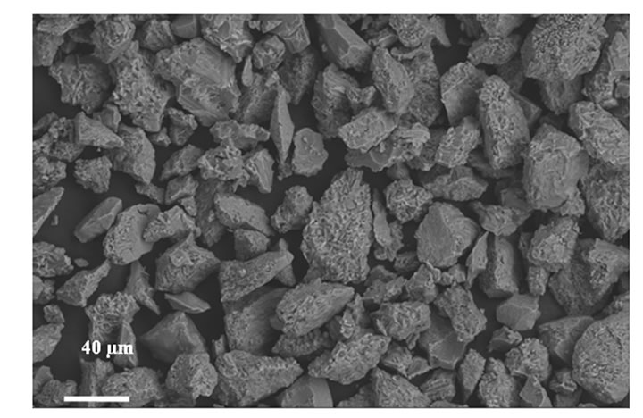
Nanostructured (2613S) and conventional (ALO187) AT- 13 feedstock powders employed in this study obtained from Inframat Corp. (Farmington, CT, USA) & Praxair, Indiana, USA. The morphologies of both AT-13 powders are shown in Figure 1. The nanostructured was agglomerated, spherical nanoparticles with high flowability and an average diameter of 30 µm. The conventional powder exhibited an angular and irregular morphology with size between 10 and 45 µm. Coatings were deposited using a Sulzer-Metco 9MB plasma torch under atmospheric conditions. Stainless steel cylindrical coupons were used as substrates. The typical spraying parameters for both conventional and nanostructured coatings are summarized in Table 1.
 (a)
(a)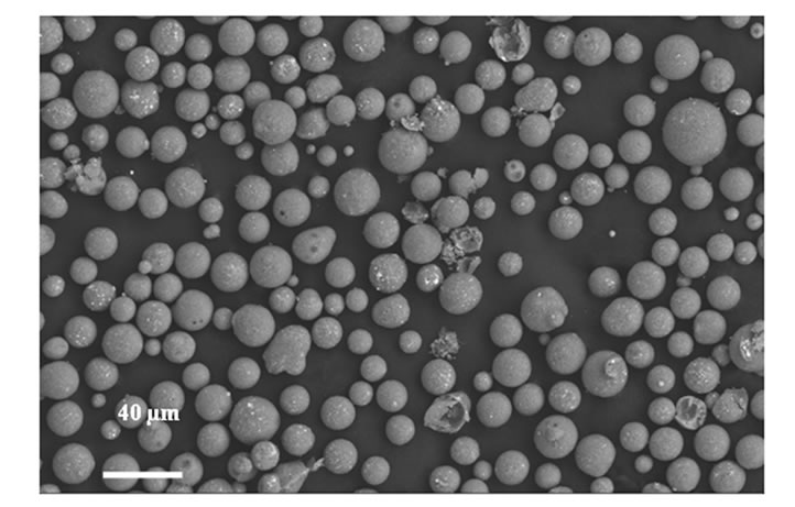 (b)
(b)
Figure 1. Morphologies of the AT-13 powders: (a) conventional; (b) nanostructured.
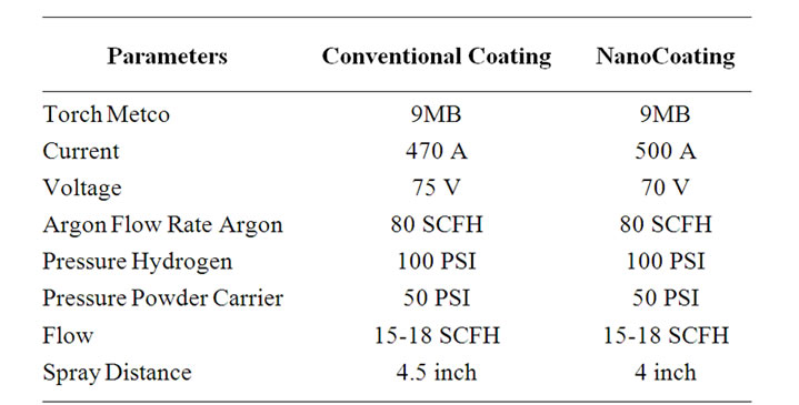
Table 1. Summary of the plasma spraying parameters.
2.2. Characterization of Coatings
The phase compositions of the as sprayed coatings were determined by X-ray diffraction (XRD) using a Philips X-ray diffractometer (Philips APD 3520). The microstructure of the as-sprayed coatings was examined by a LEO field emission scanning electron microscopy (SEM).
The microhardness measurements were conducted on the cross section of the as-sprayed coatings using Vickers Indentor. Microhardness values of the coatings were measured by digital hardness tester with load of 300 g on the cross-section of the polished samples.
2.3. Electrochemical Testing
2.3.1. Electrochemical Impedance
EIS technique was used to evaluate the electrochemical behaviour of the coated samples in 3.5% NaCl solution open to air and at room temperature for up to three weeks. A three-electrode set-up was used with impedance spectra being recorded at the corrosion potential Ecorr. A saturated calomel electrode (SCE) was used as the reference electrode. It was coupled capacitively to a Pt wire to reduce the phase shift at high frequencies. EIS was performed between 0.01 Hz and 65 kHz frequency range using a frequency response analyzer, FRA, (Autolab PGSTAT30, Eco-Chemie, The Netherlands). The amplitude of the sinusoidal voltage signal was 10mV.
2.3.2. Polarization Measurements
Linear polarization measurements were performed for the samples previously immersed for 30 minutes in 3.5% NaCl solution using Autolab PGSTAT30, Eco-Chemie, system. The scan rate was 0.05 mV/sec and the scan range was +/–20 mV with respect to the open circuit potential. The exposed surface area was 4 cm2. All curves were normalized to 1 cm2
2.4. Fatigue Testing
Rotating-beam fatigue testing was conducted on coated AISI low-carbon steel. The fatigue-testing machine is an RBF-200, rotating beam fatigue machine (Fatigue Dynamics Inc., Walled Lake, MI). The test specimen used in the fatigue testing was a 12.7 mm (1/2-inch) hourglass bar prepared according to ASTM E466 [15]. The nominal coating thickness was 100 mm (0.004 inches). The fatigue experiments were conducted at room temperature under a rotating beam fatigue and stress ratio of R = –1 configuration at a load frequency of 50 Hz. The surface of the specimen was prepared for coating by grit blasting with # 24 alumina, and no grinding was performed so as to not alter the surface roughness of the coatings. Fatigue life data generated in the fatigue tests were analyzed to determine the relationship between number of cycles to failure, N and probability of failure, Pf, for the samples tested.
3. Results and Discussion
3.1. Phase Composition of the Coatings
The XRD analysis of the AT-13 powders was confirmed in several previous studies [2-6] that both powders are prominently a-Al2O3 Rutile phase of TiO2. The XRD analysis of the conventional and nanostructured coatings are shown in Figures 2(a) and (b). The XRD patterns of the coatings show that most of a-alumina in the nanostructured powder converted into g-Al2O3 after plasma spraying process, which was similar to that in the conventionally commercial powder. It is well established that g-Al2O3 tends to be nucleated from the melt in preference to a-Al2O3 due to the higher cooling rate [4]. It can be seen from Figure 2 that both nanostructured and conventional coatings mostly contained the g-Al2O3 phase.
3.2. Microstructure of Coatings
The cross-sectional morphologies of the plasma sprayed coatings are shown in Figure 3. From the cross-sectional microstructures, it can be seen that both coatings consist of the lamella built up from the molten droplets impinging on the substrate. In case of the nanostructured coating, the interface between the steel substrate and the coating appears much stronger than that of the conventional coating. The “conventional” coating (Figure 3(a)) has a layered microstructure, typical of plasma sprayed coatings,
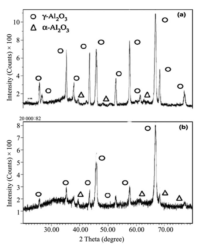
Figure 2. X-ray diffraction of the AT-13 sprayed coatings: (a) conventional coating; (b) nanostructured coating.
which is the result of full melting (FM) of the ceramic feedstock powder and its solidification as “splats” on the substrate. The FM regions in the conventional coating consist of nanocrystalline g-Al2O3 [1,17-20]. In all the coatings, some pores are observed, and splat boundaries are not clearly visible. A considerable amount (~16%) of partially melted regions (PM) is observed in the nanostructured coating (Figure 3(b)).
An SEM micrograph of the nanostructured coating is shown in Figure 3(b). This coating shows a bimodal microstructure composed of the two regions where nanopowders were fully (FM) and partially melted (PM). The partially melted region was formed when TiO2 was selectively melted because the temperature of nanopowders was not high enough during spray coating [2]. The partially melted (PM) rounded feature appears to consist of grains surrounded by a matrix phase, something similar to microstructures of liquid-phase sintered materials [6].
 (a)
(a)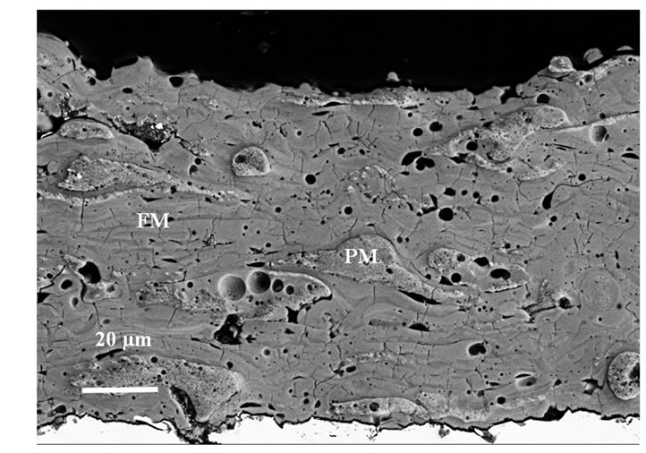 (b)
(b)
Figure 3. Cross-sectional morphologies of the as-sprayed AT-13 coatings: (a) conventional; (b) nanostructured.
Figure 4 shows a high-magnification SEM image of the partially-melted (PM) region in the nanostructured coating. The partially-molten (PM) microstructural features consists mainly of submicron a-Al2O3 fine equiaxed grains surrounded by a TiO2-rich amorphous phase.
3.3. Electrochemical Impedance Spectroscopy
EIS has been successfully applied to the study of corrosion systems for over thirty years and has been proven to be a powerful and accurate method for measuring corrosion rates especially for coatings and thin films. An important advantage of EIS over other laboratory techniques is the possibility of using very small amplitude signals without significantly disturbing the properties being measured. To make an EIS measurement, a small amplitude signal is applied to a specimen over a range of frequencies.
The expression for impedance is composed of a real and an imaginary part. If the real part is plotted on the Z axis and the imaginary part on the Y axis of a chart, we get a “Nyquist plot”. However, Nyquist plots have one major shortcoming. When you look at any data point on the plot, you cannot tell what frequency was used to record that point. Therefore other impedance plots such as “Bode plots” are important to make a correct interpretation. In Bode plots, the impedance is plotted with log frequency on the x-axis and both the absolute value of the impedance (|Z| = Z0) and phase-shift on the y-axis. Unlike the Nyquist plot, the Bode plot explicitly shows frequency information.
In this work, coated samples were immersed in NaCl solution for 21 days. Nyquist and Bode plots have been used to evaluate the corrosion resistance of the nanostructured and conventional sprayed coatings.
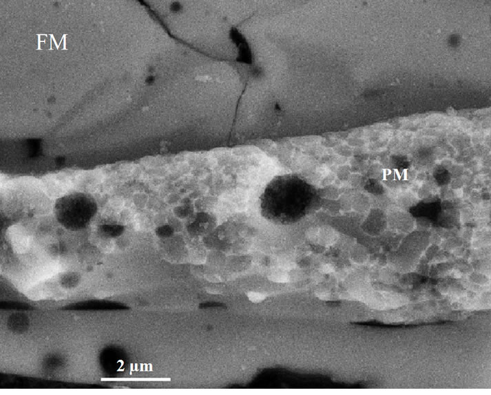
Figure 4. The partially melted region “PM” consists of α- Al2O3 (dark) embedded in TiO2-rich amorphous phase.
The EIS results shown in Figures 5 and 6 as well as the visual inspection of the tested samples suggested that the conventional sprayed samples have a strong surface resistance to chloride ion corrosion after three weeks of immersion in NaCl solution. Figure 5 (Nyquist plot) showed that the surface resistance of the conventional coated samples is 2.0 × 10⁴ Ω∙cm2 which is almost 10 times of that obtained from the nanostructured coated samples, Al-Ti N, (2.5 × 10³ Ω∙cm2).
Figure 6 indicated that the pitting resistance of the conventional coated samples was generally improved which was confirmed by the relaxation of the impedance spectra. It seems that the presence of partially melted regions (PM) in the nanostructured coating which contain many microand/or nano-pores affect negatively the the pitting corrosion resistance. Pitting corrosion can easily be done through the microor nano-pores in the nanocoatings. Therefore, the number of pitting areas increased sharply in the nanocoated samples compared with the conventional.
3.4. Linear Polarization Measurements
Polarization measurements (Figure 7) were performed for the conventional and naocoatings after 30 minutes of
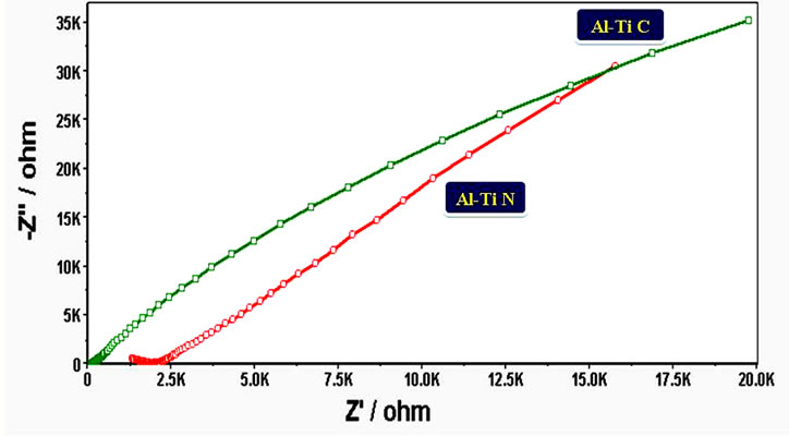
Figure 5. Electrochemical impedance spectroscopy (nyquist Plots) of alumina_titania coated samples: Al-Ti C (Conventional), Al-Ti N (Nanostructured).
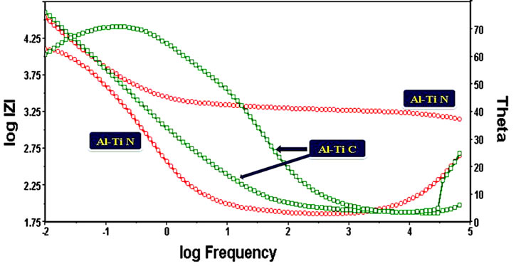
Figure 6. Electrochemical impedance spectroscopy (bode plots) of alumina-titania coated samples: Al-Ti C (Conventional), Al-Ti N (Nanostructured).
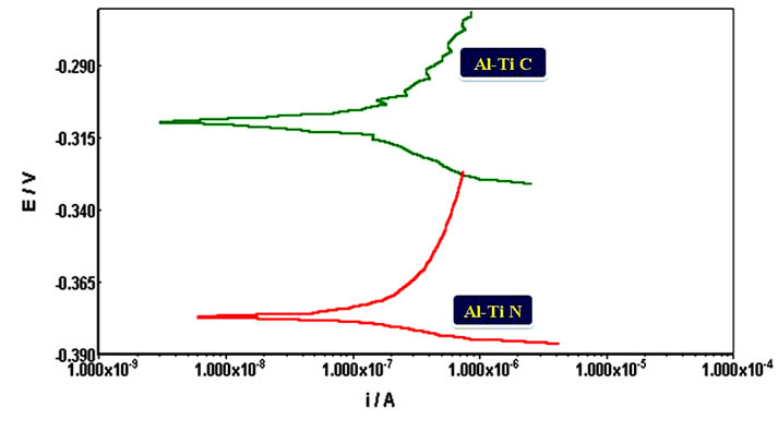
Figure 7. Polarization resistance measurments in NaCl solution.
immersion in NaCl solution. Conventional coatings samples showed a better polarization resistance than the nanocoated ones The corrosion potentioal of the conventional coated samples was shifted about 50 mV toward the passive direction compared with the nanocoated samples.
3.5. Hardness of the Coatings
Vickers microhardness measurements were performed under a 300 gf load for 15 s on the cross-sections of the coatings. A total of 10 microhardness measurements were carried out for each coating. The mean microhardness of conventional coating is about 840, which is lower than the mean microhardness of 965 achieved by the nanostructured coating. The observed hardness difference is believed to result partially from different coating microstructures and phase compositions, even though all these coatings have the same nominal chemical composition. Specifically, the distribution of TiO2 in these Al2O3/ TiO2 coatings affects the coating hardness. It is interesting to notice that the nanostructured coating contains partially melted regions (PM) contain many microor nano-pores and thus these regions should have a relatively low microhardness.
3.6. Results of the Fatigue Tests
Fatigue life data generated in the fatigue tests were analyzed to determine the relationship between stress level, S, number of cycles to failure, N and probability of failure, Pf, for the samples tested. The failure probability [12], Pf, corresponding to the order number i is given by:
 (1)
(1)
Figure 8 shows the fatigue life (cycles) at 50% failure probability for the coated and uncoated specimens. The results indicate that the nanostructured alumina-titania coating exhibited higher fatigue lives compared to the conventional alumina-titania coating. The increase in the
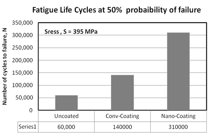
Figure 8. Fatigue life (cycles) for coated and uncoated specimens.
fatigue strength of nanostructured coatings can be related to the crack propagation resistance of these coatings. Several investigators have shown that the crack propagation resistance of nanostructured coatings is superior to that of the conventional coatings [2,19,20]. It is important to notice that the partially melted (PM) regions in the coating act as a crack arrest as seen in Figure 3. Another important factor that can play a major role in increasing the fatigue resistance is the interfacial toughness. Bansal et al. [20] have measured the interfacial toughness of the conventional and the nanostructured AT-13 plasma prayed coatings on steel substrates; the values were 22 and 45 J·m–2, respectively.
4. Conclusions
• The microstructure of the conventional coating consists primarily of fully-molten (FM) regions. The microstructure of nanostructured coating is a bimodal in nature and it consists of regions of (FM) mixed with partially-molten (PM) microstructural features.
• The presence of the partially melted (PM) region in the nanostructured coating act as a crack arrest and play a major rule in strengthening the crack propagation resistance.
• The significant increase in the fatigue strength of the nanostructured coatings compared to the conventional coating is attributed to the improvement in the crack propagation resistance resulted from the presence of the partially melted (PM) region.
• The presence of the partially melted regions (PM) in the nanostructured coating which contain many microand nano-pores affect negatively the pitting corrosion resistance. Therefore, conventional coatings showed a much better localized corrosion resistance than the nanocoatings.
REFERENCES
- J. Iwaszko, “Surface Remelting Treatment of PlasmaSprayed Al2O3 + 13 wt% TiO2 Coatings,” Surface and Coatings Technology, Vol. 201, No. 6, 2006, pp. 3443- 3451. doi:10.1016/j.surfcoat.2006.07.234
- E. H. Jordan, M. Gell and Y. H. Sohn, et al., “Fabrication and Evaluation of Plasma Sprayed Nanostructured Alumina-Titania Coatings with Superior Properties,” Materials Science and Engineering A, Vol. 301, No. 1, 2001, pp. 80-89. doi:10.1016/S0921-5093(00)01382-4
- E. Song, J. Ahn, S. Lee and N. Kim, “Effects of Critical Plasma Spray Parameter and Spray Distance on Wear Resistance of Al2O3 – 8 wt% TiO2 Coating PlasmaSprayed with Nanopowders,” Surface & Coatings Technology, Vol. 202, No. 2, 2008, pp. 3625-3632.
- M. Gell, E. H. Jordan, Y. H. Sohn, D. Goberman, L. Shaw and T. D. Xiao, “Development and Implementation of Plasma Sprayed Nanostructured Ceramic Coatings,” Surface and Coating Technology, Vol. 146-147, No. 1, 2001, pp. 48-54. doi:10.1016/S0257-8972(01)01470-0
- A. Ibrahim, H. Salem and S. Sedky, “Excimer Laser Surface Treatment of Plasma Sprayed Al2O3 + 13 wt% TiO2 Coatings,” Surface and Coating Technology, Vol. 203, No. 2, 2009, pp. 3579-3589. doi:10.1016/j.surfcoat.2009.05.034
- D. Goberman, Y. H. Sohn, L. Shaw, E. Jordan and M. Gell, “Microstructure Development of Al2O3 – 13 wt% TiO2 Plasma Sprayed Coatings Derived from Nanocrystalline Powders,” Acta Materialia, Vol. 50, No. 5, 2002, pp. 1141-1152. doi:10.1016/S1359-6454(01)00414-1
- H. Gleiter, “Nanostuctured Materials: Basic Concepts and Microstructure,” Acta Materialia, Vol. 48, No. 1, 2000, pp. 1-29. doi:10.1016/S1359-6454(99)00285-2
- M. Wang and L. Shaw, “Effects of Powder Manufacturing Methods on Microstructure and Wear Performance of Plasma Sprayed Alumina-Titania Coaings,” Surface and Coating Technology, Vol. 202, No. 1, 2007, pp. 34-44. doi:10.1016/j.surfcoat.2007.04.057
- J. Zhang, Z. Wang, P. Lin, W. LU, Z. Zhou and S. Jiang, “Effect of Sealing Treatment on the corrosion resistance of Plasma-Sprayed NiCrAl/Cr2O3 – 8 wt% TiO2 Coating,” Journal of Thermal Spray Technolog, Vol. 20, No. 3, 2010, pp. 508-513. doi:10.1007/s11666-010-9528-6
- S. Liscano, L. Gil and M. H. Staia, “Effect of Sealing Treatment on the Corrosion Resistance of Thermal-Sprayed Ceramic Coatings,” Surface and Coatings Technology, Vol. 188-189, No. 1, 2004, pp. 135-139. doi:10.1016/j.surfcoat.2004.08.009
- J. Creus, H. Idrissi, H. Mazille, F. Sanchette and P. Jacquot, “Corrosion Behaviour of Al/Ti Coating Elaborated by Cathodic Arc PVD Process onto Mild Steel SubStrate,” Thin Solid Films, Vol. 346, No. 1-2, 1999, pp. 150-154.
- A. Ibrahim and C. Berndt, “The Effect of High-Velocity Oxygen Fuel, Thermally Sprayed WC-Co on the High Cycle Fatigue (HCF) of Aluminum and Steel Thermally Sprayed with WC-Co,” Journal of Material Science, Vol. 33, No. 2, 1998, pp. 3095-3100.
- A. Ibrahim and C. Berndt, “Fatigue and Deformations of HVOF Sprayed WC-Co Coatings vs. Hard Chrome Plating,” International Thermal Spray Conference, Vol. 1, No. 1, 2003, pp. 377-380.
- H. J. C. Voorwald, R. C. Souza, W. L. Pigatin and M. O. H. Cioffi, “Evaluation of WC-17Co and WC-10Co-4Cr Thermal Spray Coatings by HVOF on the Fatigue and Corrosion Strength of AISI 4340 Steel,” Surface and Coatings Technology, Vol. 190, No. 2, 2005, pp. 154-164. doi:10.1016/j.surfcoat.2004.08.181
- R. Ahmed and M. Hadfield, “Mechanisms of Fatigue Failure in Thermal Spray Coatings,” Journal of Thermal Spray Technology, Vol. 11, No. 3, 2002, pp. 333-349. doi:10.1361/105996302770348727
- Y. Wang, S. Jiang, M. Wang, S. Wang, T. D. Xiao and P. R. Strutt, “Abrasive Wear Characteristics of Plasma Sprayed Nanostructured Alumina/Titania Coatings,” Wear, Vol. 237, No. 1, 1999, pp. 176-185.
- R. S. Lima and B. R. Marple, “Process-Property-Performance Relationships for Titanium Dioxide Coatings Engineered from Nanostructured and Conventional Powders,” Materials & Design, Vol. 29, No. 1, 2008, pp. 1845- 1855. doi:10.1016/j.matdes.2008.03.005
- R. S. Lima, S. Dimitrievska , M. N. Bureau, B. R. Marple, A. Petit, F. Mwale and J. Antoniou, “HVOF-Sprayed Nano TiO2-HA Coatings Exhibiting Enhanced Biocompatibility,” Journal of Thermal Spray Technology, Vol. 19, No. 1-2, 2010, pp. 336-343. doi:10.1007/s11666-009-9442-y
- R. S. Lima and B. R. Marple, “Thermal Spray Coatings Engineered from Nanostructured Ceramic Powders for Structural, Thermal Barrier and Biomedical Applications: A Review,” Journal of Thermal Spray Technology, Vol. 16, No. 1, 2007, pp. 40-63. doi:10.1007/s11666-006-9010-7
- P. Bansal, N. P. Padture and A. Vasiliev, “Improved Interfacial Mechanical Properties of Al2O3 – 13 wt% TiO2 Plasmasprayed Coatings Derived from Nanocrystalline Powders,” Acta Materials, Vol. 51, No. 10, 2003, pp. 2959-2970. doi:10.1016/S1359-6454(03)00109-5