Microscopy Research
Vol.2 No.1(2014), Article ID:42303,5 pages DOI:10.4236/mr.2014.21003
Microscopic Characterization of Ecological Concrete Polymeric
![]()
1Centro de Investigación en Ingeniería y Ciencias Aplicadas, Universidad Autónoma del Estado de Morelos, Cuernavaca, México; 2Facultad de Ciencias Químicas e Ingeniería, Universidad Autónoma del Estado de Morelos, Cuernavaca, México.
Email: delia_rm@yahoo.com.mx
Copyright © 2014 A. D. Rodríguez et al. This is an open access article distributed under the Creative Commons Attribution License, which permits unrestricted use, distribution, and reproduction in any medium, provided the original work is properly cited. In accordance of the Creative Commons Attribution License all Copyrights © 2014 are reserved for SCIRP and the owner of the intellectual property A. D. Rodríguez et al. All Copyright © 2014 are guarded by law and by SCIRP as a guardian.
Received November 14th, 2013; revised December 23rd, 2013; accepted January 10th, 2014
KEYWORDS
Polymer Concrete; Polymer Blend
ABSTRACT
The Scanning Electron Microscopy (SEM) and Optical Microscopy (OM) with integrated digital camera are techniques that are used in the present investigation, for the morphological characterization of a new composite material called “organic polymer concrete” in which microparticles added fibers and polyethylene terephthalate (PET) recycling mechanically (RM). Polymer concrete (PC) is a new composite material (MC) in the application considered as an alternative material of construction in which reinforcement particles are recycled polymers which have approximately the same dimensions in all directions. Therefore, the particles can be rods, spheres, chips and many other shapes whose appearance reasons are about 10 microns. These MC, the size, shape and distribution and the ratio and the modulus of the particles affect the properties of the material.
1. Introduction
At present, the science and engineering of materials focuses on the development of new synthetic methods, new ways to identify and characterize materials, a description of its structure, synthesis and custom design and innovate to obtain new materials with desired properties and controllable [1]. There are several ways to classify the materials. One of them is to describe the following groups: metals and alloys, ceramics, glasses and glass-ceramics, polymers (plastics), semiconductors, composites and biological materials. According to the above classification, the materials used for this study were classified into composite polymeric materials, because when there is the combination of solid materials, obtaining the new composite material is that it is called “polymer concrete”.
In this research, paper presents the microscopic characterization of a new polymer concrete using as raw material polyethylene terephthalate (PET) recycling mechanically because it is considered a 100 percent recyclable plastic based on the emerging Mexican standard NMX-E-232-SCFI-1999 of the Ministry of Commerce and Industrial Development. Note that in our country (Mexico), PET plastic waste is the second most important for their consumption as disposable bottles and recyclable municipal solid waste. Besides, primary or mechanical recycling is a feasible process for the revaluation of recyclable waste such as PET [2]. The process for obtaining the polymer concrete is considered technical, environmental and economically feasible to continue proposing it as a new composite material for their high mechanical strength.
1.1. Polymer Blends
The mixtures are combinations of polymers by mechanical means. Such combinations do not depend on chemical bonds, but typically require compatibilizers that prevent the segregation of components. In mixtures typically kept the best characteristics and in many cases the object is to find two or more components which, when mixed, produce synergistic improvement of the properties beyond those that are purely additive in their effect. The improvements sought are in the areas of impact resistance, weatherability, better low temperature performance and flame retardancy [2]. Research from 1990 to 2000 are focused on the combination of polymers to form plastic polymer blends and alloys when added coupling agents or compatibilizers as silanes, titanates and thermoplastic rubbers, innovation is what moves the technological development of the industry [3]. Plastics are the most important polymers in the market for production tonnage and the products it generates, an important point is that it is a new design material in more than 300 years and building it competes with steel, glass, wood, aluminum and many other materials and even with the same by its versatility [4].
Some of the microscopy techniques which are used to characterize composite materials are optical microscopes with integrated digital camera, SEM (scanning electron microscope), AFM (atomic force electron microscope) DRx (XRD). In particular, spectroscopic techniques were used in this research for the morphological characterization of the new composite material RPET mechanically. Polymeric concrete was conducted with the following equipment: Optical Microscope and Scanning Electron Microscope (SEM).
1.2. Optical Microscope (OM)
The micrographs obtained in metallographic microscope can be expanded due to the inclusion of various auxiliary devices such as for observing the structural features that are not visible to normal conditions. Minimum and maximum amplification obtained with the microscope Olympus brand and model GX71 is 50× to 2000× (Figure 1) with adaptation of a data acquisition system. The main limitation is the wavelength of visible light, which limits the resolution of fine details of the solid sample. The phase differences caused by variations in the level of extremely small microstructures, transform later on intensity differences in the observed image, thereby revealing aspects invisible under ordinary lighting.
1.3. Electron Microscope (SEM)
The main parts of SEM are: Electron gun, light source, magnetic lenses (condenser, objective), scanning coils (directs the beam), 2 detectors (Rx, secondary electrons), columns, camera, vacuum system, software for 3D structure and organic samples, mapping of chemical elements in the sample, secondary electrons gives threedimensional images. The SEM, JEOL model VP 1450 (Figure 2) is equipped with an energy dispersive spectrometer (EDS) allowing chemical analysis on the sur-

Figure 1. Optical microscope with a camera.
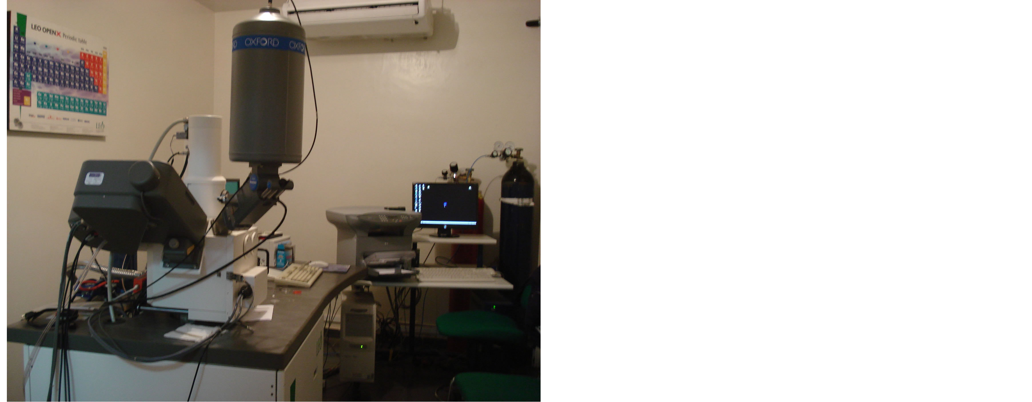
Figure 2. Scanning electron microscope.
faces of the samples. The high resolution on this computer to monitor rainfall inclusions, second phase particles with diameters of 1 - 2 microns. Images are formed by gathering or bouncing electrons are emitted from the surface of the sample when it is scanned by a beam of high energy electrons. The image formed is an extension of some detail of the sample, as would a light microscope. The difference lies, however, in the high resolution and depth of field you can achieve with the SEM; observation has two modes, one shows the signal produced by the secondary electrons and the other the signal produced by electrons scattered retro. The signal produced by secondary electrons is much more sensitive to topographical changes to changes in composition in a sample. Instead, retro scattered signal is much more sensitive to changes in composition and is very sensitive regarding topographic changes. For this reason, the secondary electron signal is used to examine the sample [5].
1.4. Evaporator
From the samples prepared by the method of evaporating gold-palladium (Au-Pd) through ionized plasma for surface coating of the polymeric material powder, in order to obtain driving inside the SEM chamber and observe morphologies present samples, for which we use a Sputter Coater Polaron evaporator brand, model SC7620 (Figure 3) [6].
2. Methodology
2.1. Preparation of Polymer Concrete Sample Mechanically Recycled PET
Raw Material: microfiber Particulates and mechanically recycled polyethylene terephthalate, polyester resin and calcium carbonate.
A homogeneous mixture is produced which contains polyester resin and calcium carbonate particulates and recycled polyethylene terephthalate microfibers mechanically conventional mill ratio (1:1:1) is poured into molds of HDPE into the desired shape (cube, cylinders, tablets) and allowed to dry at room temperature (26˚C to 32˚C) for about 6 hours.
The equipment used for the characterization of materials by microscopic analysis are:
2.2. Preparation of Sample for Analysis in Optical Microscope with Integrated Digital Camera
It breaks the sample of CP with MR PET electric cutter diamond tipped, solid surface for approximately 1 cm2, which is observed in the MO.
2.3. Preparation of Sample for Analysis in Scanning Electron Microscope
Sample is crushed recycled PET polymer concrete mechanically vibrating mill until fine powders that are placed in a stainless steel sample holder on which is fixed graphite tape, then placed the sample holder with the powder an evaporator (sputtering) for about 6 minutes, where gas is flowed argon inert element and have vacuum in the evaporator chamber to prevent sample contamination. This sample preparation technique using a target of palladium gold which has the function fragments powder coating of the polymeric material by deposition, in order to obtain a sample metal (conductive) and subsequently can be observed in the SEM.
3. Results
3.1. Microscopic Characterization of Surface Composite (Sliver)
Optical Microscope Images. In Figures 4 and 5 are images that were obtained in the MO of the composite surface “Polymeric Concrete RM PET”.

Figure 3. Evaporating metal coating (Au-Pd) in non-conductive samples.

Figure 4. Image of the surface microstructure of the composite, (MO, 10x magnification).

Figure 5. Image of the surface microstructure of the composite, (MO, 20× magnification).
3.2. Microscopic Characterization of Composite (Spray)
Micrographs of scanning electron microscope (SEM). Were obtained in the SEM micrographs of the combination of materials used in the concrete samples obtained polymeric RPET and thus observe the structure of the materials which in combination form the CP.
3.3. Characterization of Fractured Composite
To characterize the composite fractured fragment is a sample to observe the solid structure in its thickness.
In the images of Figures 4 and 5 which were obtained in the MO with a magnification of 10× and 20×, into an area of the sample surface are observed pores with a size of about 8 μm, and also shows the presence of pores larger than about 200 μm, this manual mixing because that is applied during the preparation of PET RM CP.
In Figure 6 the composite panoramic image contrast observed in white crystalline particles in the form of elongated rods of approximately 100 μm, because of the presence of microfibers mechanically recycled polyethylene terephthalate.
In the photomicrographs of Figures 7 and 8 show crystal morphology particles with rod-shaped or elongated thin fibers and PET RM (a).
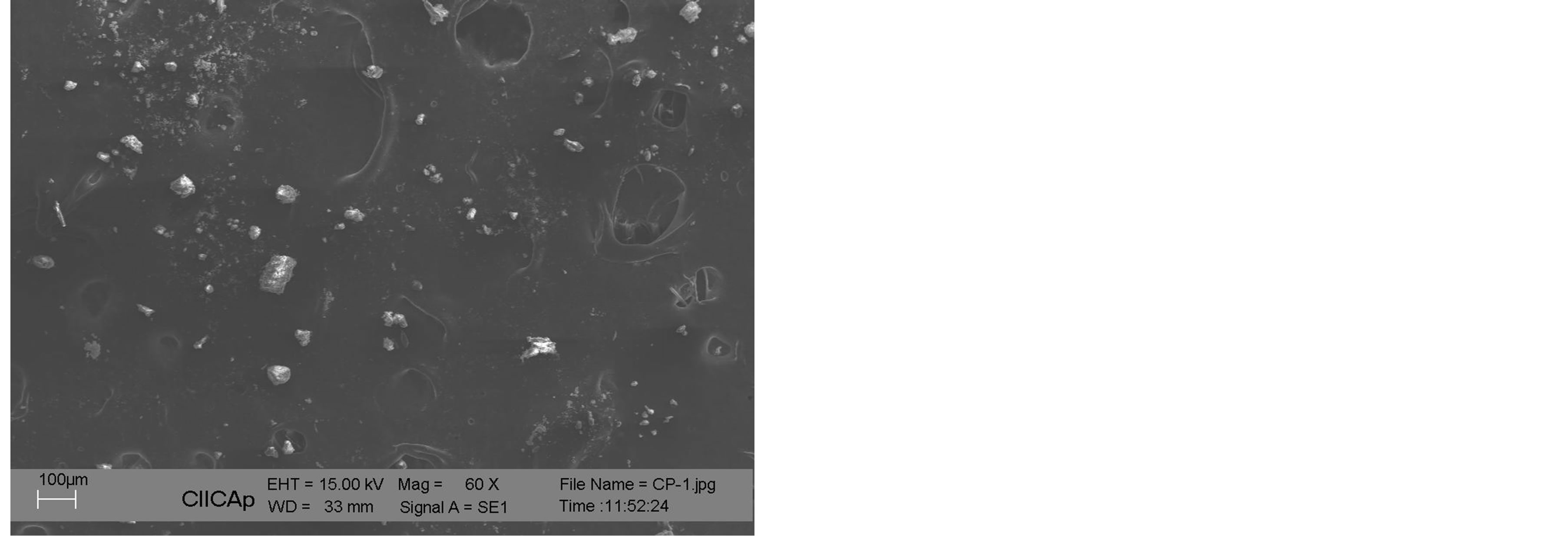
Figure 6. Panoramic image of the composite material, called “concrete polymeric recyclable polyethylene terephthalate”.

Figure 7. Image of a localized area of the CP with RPET, pulverized.
Figure 9 shows that a panoramic image of a blockshaped piece of solid composite material is fractured.
Figure 10 is observed in the presence of dark areas brittle fractures (a), in the light areas of the material plastic deformation (b) and formation of cleavage rivers (c).
In Figure 11, if there are particles less than 10 μ (a) of
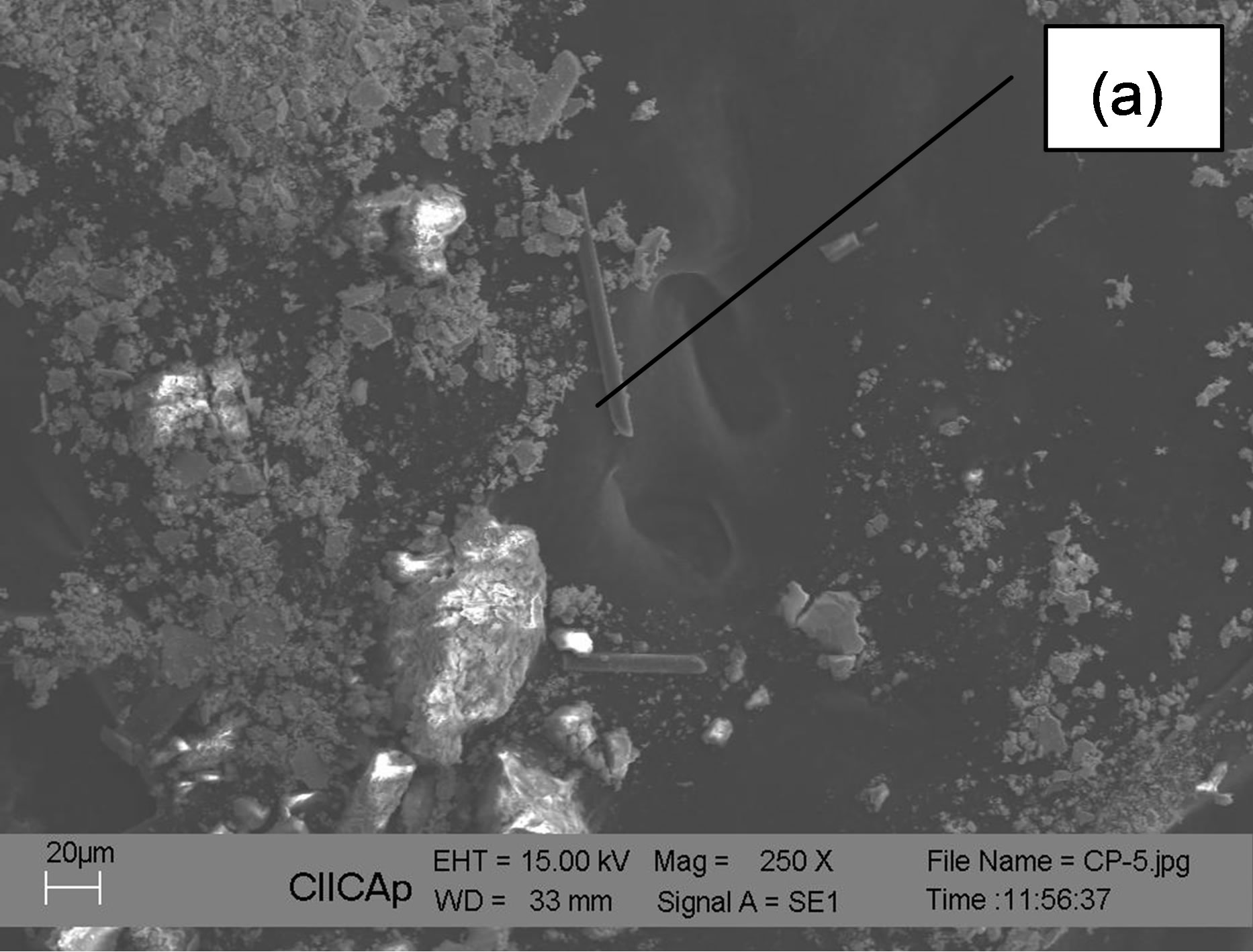
Figure 8. An image area of the composite powder.

Figure 9. Panoramic image of a block-shaped fragment of broken solid composite material.

Figure 10. Detail of a fractured zone.

Figure 11. Detail of a granular fracture site.
different phases and grains larger than about 60 μ in some grains, type crystal morphologies (b) are staggered.
Acknowledgements
The authors are grateful to the support of the Centre for Research in Engineering and Applied Sciences at the Autonomous University of the State of Morelos.
REFERENCES
- W. F. Smith, “Fundamentals of Materials Science and Engineering,” 3rd Edition, McGraw Hill, New York, 2003.
- P. L. Mangonon, “Science of Materials,” Institute of Technology, Prentice Hall Pearson Education, Florida, 2001.
- O. R. Blanco, “Enciclopedia del Plástico 2000,” Tercera Edición, Instituto Mexicano del Plástico Industrial S.C. México D.F., 2000.
- M. J. Morales, “Eduardo Introducción a la Ciencia y Tecnología de los Plásticos,” Editorial Trillas, S.A. de C.V. 2010.
- J. I. Goldstein, D. E. Newbury, P. Echlin, D. C. Joy, A. D. Romig, C. E. Lyman, C. Floril and E. Lifshin. “Scanning Electron Microscopy and X-Ray Analisys,” Plenum Press, New York, 1992. http://dx.doi.org/10.1007/978-1-4613-0491-3
- T. R. Guardián, “Modificación Superficial de Aceros de Aplicación Industrial,” Tesis profesional de Doctorado Centro de Investigación en Ingeniería y Ciencias Aplicadas, Universidad Autónoma del Estado de Morelos, Cuernavaca, 2010.