World Journal of Nuclear Science and Technology
Vol.2 No.1(2012), Article ID:16567,7 pages DOI:10.4236/wjnst.2012.21003
Localization of Plastic Deformation in Copper Canisters for Spent Nuclear Fuel
Laboratory of Engineering Materials, School of Engineering, Aalto University, Espoo, Finland
Email: *Kati.Savolainen@hut.fi
Received October 3, 2011; revised November 4, 2011; accepted December 8, 2011
Keywords: Copper; Deformation; Localization; Friction Stir Welding; Electron Beam Welding
ABSTRACT
Localization of plastic deformation in different parts (extruded and forged base materials as well as EB and FSW welds) of the corrosion barrier copper canister for final disposal of spent nuclear fuel was studied using tensile testing, optical strain measurement, scanning electron microscopy (SEM), and electron back-scatter diffraction (EBSD). Results show that in the base materials plastic deformation occurs very uniformly. In FSW welds the deformation localizes in the weld either at the processing line or at a line of entrapped oxide particles. In EB welds the deformation localizes to the equally oriented large grains at the weld centreline or at the steep grain size gradient in the fusion line.
1. Introduction
In Finland and Sweden the spent nuclear fuel will be encapsulated and deposited into long-term repositories deep in the bedrock [1,2]. The spent nuclear fuel will be placed in cast iron inserts surrounded by corrosion barrier copper canisters. The 50 mm thick copper canisters consist of an extruded tubular body and forged lid and bottom parts. The tubes and the lids/bottoms will be joined using either electron beam (EB) or friction stir welding (FSW). Different parts of the copper canister have inhomogeneous grain structures and the canister itself contains discontinuities and welds as well as possible minor defects, which cause stress concentrations. These regions may have a significant influence on the deformation of the canister during its lifetime, and their impact on the damage tolerance of the copper canister must be known. Plastic deformation of the canister caused by the repository conditions, such as hydrostatic pressure and bentonite swelling, will not be distributed evenly around the canister, but instead it will concentrate to certain locations. Microstructural defects, geometric discontinuities, as well as microstructural heterogeneity and residual stresses and strains of the welds, in particular, localize plastic deformation.
Residual stress and strain profiles in constrained thicksection copper welds on a local scale and their relaxation under creep and irradiation has not been assessed in detail. Also the relationship of strain localization and strain history to cold work distribution in copper canister has not been explored. The amount of residual plastic strain is known to have an effect on different long-term materials properties. For instance, effect of prestrain (dislocation density) on creep of copper has been shown [3]. In austenitic AISI 304 stainless steel the amount of cold work exceeding 20% is known to result in initiation of the stress corrosion cracking [4]. Thus, when wanting to ascertain and evaluate the integrity of the copper canister it is very important to know the material properties even in very small localized areas. Electron backscatter diffraction (EBSD) and electron microscopy have in recent years proved to be a promising method to study the plastic strain and other material properties in localized areas. However, due to time constraint when wanting to map large areas, it is beneficial to be able to concentrate only on the critical areas. The different regions of a weld are typically exhibiting large variations of residual plastic strain and various discontinuities in the material properties. The optical strain measurement using large test samples containing the whole weld area is an ideal method to detect the critical areas for strain localization, which can later be studied with electron microscopy in detail.
Welding of 50 mm thick copper is difficult and the two currently available methods are EBW and FSW. In EBW, a beam of high-energy electrons locally melts the material to be welded and as the beam passes, the material solidifies producing a very distinctive grain structure. Solidification initiates epitaxially on the base material on both sides of the weld [5]. The solidification forms long columnar grains, which turn to the welding direction (Figure 1). At the centreline of the weld the long columnar grains are almost parallel to the welding direction. The

Figure 1. Macrograph of the transverse cross-section of an EB weld. Tube material is on the left side and lid material on the right side. The large grain size of the weld can be clearly seen. Fracture locations are marked with black lines. Thickness of the joint is 50 mm.
morphology of the grain structure can be controlled by several EB welding parameters, e.g. the acceleration voltage and the current of the electron beam and the welding speed. FSW is a solid state welding method, where a rotating tool with complicated features is plunged between the work pieces. The frictional heat between the tool and the work pieces plasticises the base material without melting it. The resulting microstructure has an equiaxed, small grain size and nearly random texture, similar to that of the base materials. Properties of the FSW welds have been reported to be very close to those of the base materials [6].
The aim of this study was to determine where the plastic deformation localizes in different parts of the copper canister. Different manufacturing and welding methods result in different microstructures. Samples of the extruded and forged base materials as well as EB and FSW welds transverse to the welding direction were tensile tested. An optical strain measurement system comprising of a CCD camera and a PC with an imaging software was used to measure and analyze the plastic deformation of the samples during tensile testing. The system records successive images of the sample surface and constructs the deformation field using advanced cross-correlation algorithms. Many studies have shown the usefulness of the OIC/DIC method in determining the mechanical properties of the welds [7-9].
2. Material and Methods
The base material was hot-worked phosphorus-doped (40 ppm) oxygen-free copper (Cu-OFP). The base materials of the forged lids and extruded tubes are slightly different depending on the manufacturing method. Therefore, the base materials of the studied welds were different. Due to their similarity and restrictions in the amount of available test material, optical strain measurements were made only with tube material of the EB weld and lid material of the FSW weld. Forged and extruded base materials have a small grain size (appr. 75 µm).
Tensile testing was performed by a MTS 810 material test system at three strain rates: 10–4, 10–5, and 10–6 1/s using flat dog-bone shaped tensile test samples. The tensile test samples were electro-discharge machined from full-size welding trial canisters with specific canister geometries for both welding methods. Gauge length of the samples was 40 mm, width 35 mm, and thickness 5 mm. Welds were located at the centre of the gauge length of the cross-weld specimens. Images for optical strain measurement were obtained at a rate of 0.3 Hz during tensile testing. Deformation fields were determined using StrainMaster optical strain measurement system by LaVision. Sample preparation for FEG-SEM/EBSD was made using SiC grinding papers, diamond polishing up to 1 µm, and electrolytic polishing. Zeiss Ultra 55 FEG-SEM and Channel 5 acquisition and analysis software by HKL Technologies were used in SEM and EBSD studies. For macroscopic studies the samples were etched using 50%/ 50% solution of distilled water and nitric acid for 60 s. Experimental methods to reveal the processing lines of FSW welds were developed using optimized values of electrolytic polishing.
3. Results
Figure 2 shows stress-strain curves for the test samples tested at strain rate 10–4 1/s. It can be seen that the tensile strength of the EB weld is lower than that of the other samples. Tensile strength of the EB weld is 175 MPa while the other samples have a tensile strength of 200 MPa or higher. The extruded tube material has the highest tensile strength of 210 MPa. It can also be seen that the elongation to fracture of the EB weld is significantly lower compared to the other materials. Yield strength was 75 MPa for the tube material and EB weld, 95 MPa for the FSW weld, and 105 MPa for the lid material.
The effect of the strain rate in the studied range was negligible, as the tensile properties and fracture locations were the same for all corresponding test samples regardless of the strain rate. EB welds exhibited lowest tensile properties, while FSW welds showed tensile properties comparable to those of the base materials. Figure 3 shows the final fracture of the cross-weld specimens of EB and FSW welds exhibiting the location of fracture in EB weld in the middle of the weld and partially along the fusion line between the weld metal and the lid material and in FSW weld fracture occurs along the line of entrapped oxide particles and the nearby processing line. In the base material specimens plastic deformation occurred very uniformly and fracture took place at the centre of the gauge
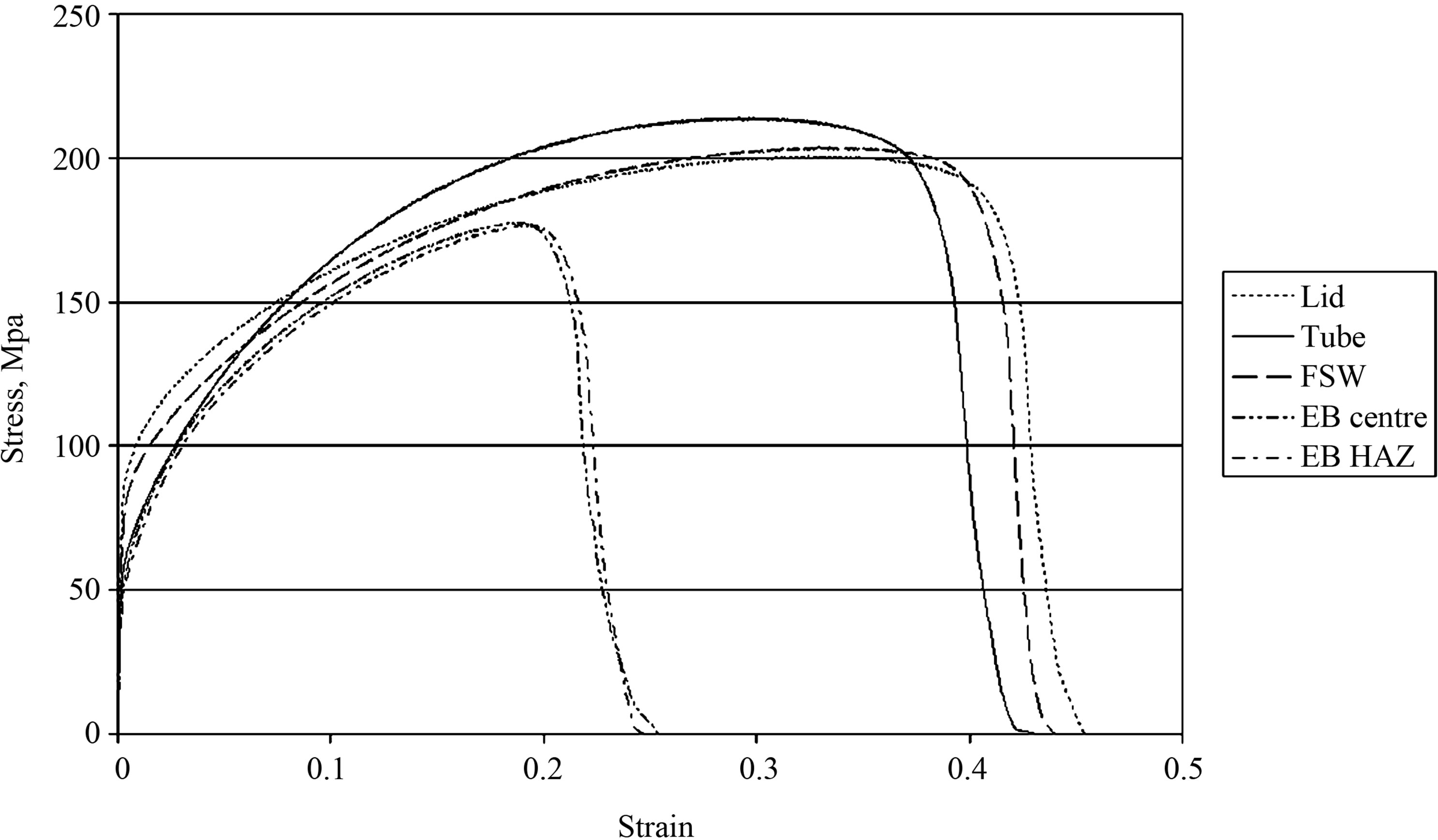
Figure 2. Stress-strain curves of test samples tested at strain rate 10–4 1/s. Tensile strength of the EB weld is low compared to that of the other samples, 175 MPa as compared to 200 MPa or higher and the uniform elongation is about half of that of the FSW weld and the lid and tube base materials.
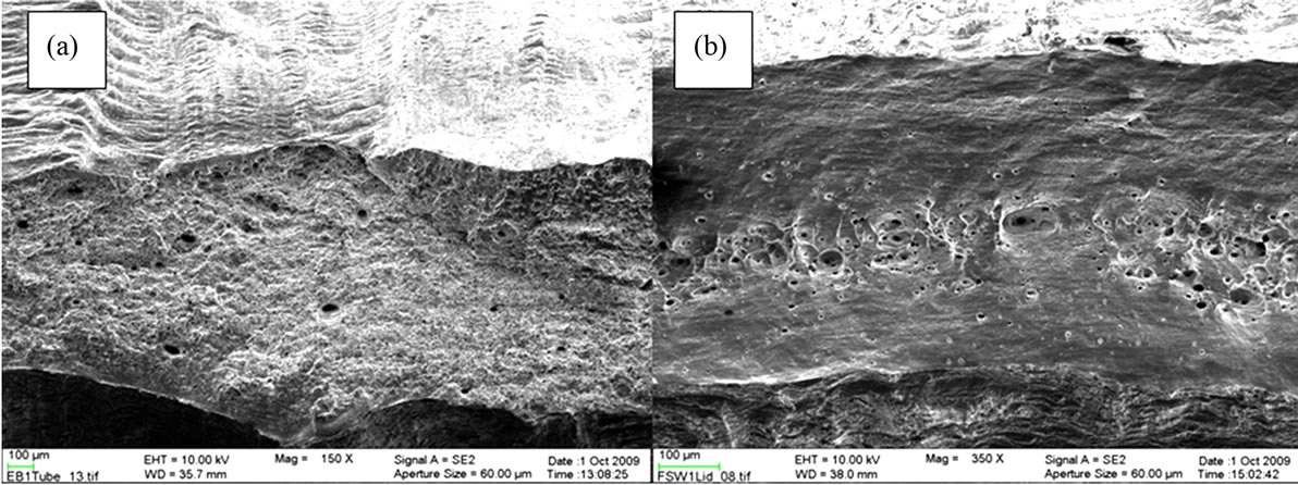
Figure 3. Examples of the fracture surfaces of cross-weld samples of (a) EB weld and (b) FSW weld showing the final ductile fracture mode and location of fracture in the weld metal.
length. Dimples and shear lips indicate a ductile fracture process. EB weld shows ductile shear fracture through the whole specimen. The appearance differs significantly from those of the FSW and the base materials where the shear lips formed on both side surfaces of the specimens.
Macrographs of the transverse sections of the studied FSW and EB welds are shown in Figures 4 and 1, respectively. Although both FSW and EB welds are heterogeneous, it can be seen that the grain size variation in the EB weld is significantly higher than that in the FSW weld. In FSW weld the grain size is slightly smaller than in the base materials (60 µm and 75 µm, respectively). The grain size in the EB weld can reach up to 12 mm. Fracture localizes in specific locations in the studied cross-weld specimens similarly at all strain rates used in the mechanical testing. The fracture locations are marked by black lines in the figures. FSW welds fracture either at a processing line or a line of the entrapped oxide particles (see details

Figure 4. Macrograph of the transverse cross-section of an FSW weld. Tube material is on the right side and lid material on the left side. Different zones of the weld can be clearly seen. Fracture locations are marked with a black line. Thickness of the joint is 50 mm.
in Figure 5). Processing lines in the FSW welds are due to the etching effects revealed by the experimental electrolytic polishing method used. As can be seen from Figures 5(a) and (b) the processing line is not connected to any texture change or with local variation of residual strain in the weld metal. EB welds fractured either at the centreline of the weld or at the fusion line between the weld metal and the lid material (see details in Figures 6 and 7). Based on the finite element (FE) modelling of an isotropic Cu-OFP material, the fracture occurs and deformation localizes at a different location than it does in the weld metal containing cross-weld samples.
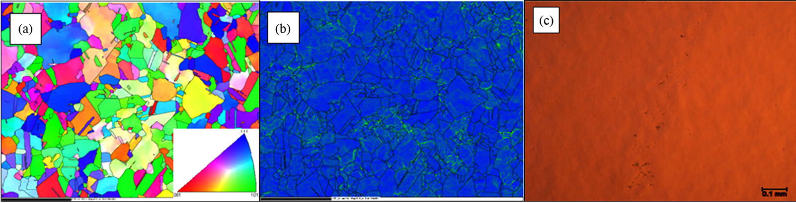
Figure 5. Details of the fracture locations in FSW welds. (a) Inverse pole figure EBSD map and (b) local misorientation map of the processing line (scale bar is 100 µm) in the middle of the pictures. Colour key for the IPF map is shown in the insert and for the local misorientation map the colour key is the same as in Figure 6. There is no change in texture or distribution of residual strain (green colour) in the area of the processing line. Only a line of slightly smaller grain size can be vaguely discerned. (c) Optical microscopy image of the entrapped oxide particle line.
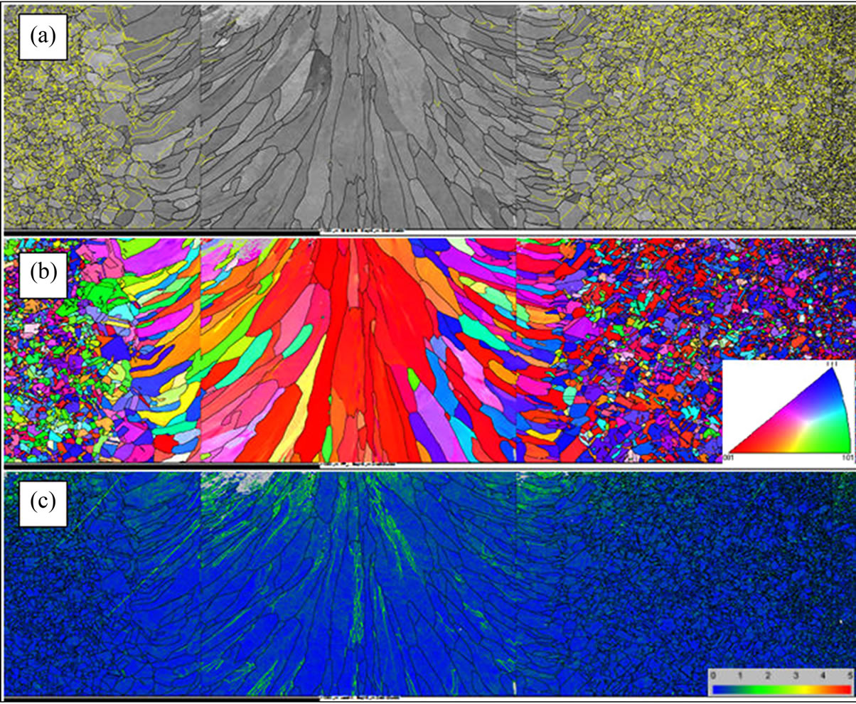
Figure 6. EBSD maps of a horizontal cross-section (top view) of the EB weld; lid base material is on the left side. (a) Pattern quality map shows the distribution of the grain size in the weld metal and the base materials. The yellow lines show twin boundaries inside the grains of the base materials. In the solidified weld metal twin boundaries are not present except in some grains close to the fusion line. (b) Inverse pole figure map (IPF) in the Z-direction shows that in the middle of the EB weld a highly oriented microstructure with <100> direction is dominating. (c) Local misorientation map shows the local concentration of higher strain (green colour) at the centreline of the weld and close to the fusion line between the weld metal and the base materials. Colour keys for the IPF and local misorientation maps are shown in the inserts.

Figure 7. EBSD maps of the transverse cross-section of the EB weld. (a) Local misorientation map of the entire width of the weld; (b) High magnification IFP map of the centre line of the weld (colour key is shown in the insert); (c) Local misorientation map of the same area as in (b). Weld defect close to the fusion line in (a) does not show any marked residual strain accumulation. The colour key for the local misorientation maps is the same as in Figure 6.
Using the specially developed macro-etching technique and electrolytic polishing techniques, different areas and processing lines can be discerned by naked eye from the macro cross-section of the FSW weld. Especially the electrolytic polishing method reveals specific processing lines, which reflect light differently from the surrounding material. Even though these features and processing lines can be detected by naked eye or with small magnification stereo microscopy, they are very difficult to find in a SEM either in normal mode or using the EBSD mapping. This reveals that there are no easily discernible differences in grain size or orientation across these lines, as seen in Figure 5(a). Figure 5(b) shows a typical local misorientation map of the dynamically recrystallized structure, in which some areas of the grains are just recrystallized (blue areas) and the continued deformation induces new strain (green areas) in the newly recrystallized grains. Also, in micro-hardness testing there are no differences in hardness across the processing lines. there are no differences in hardness across the processing lines. When using the intentionally too cold processing parameters some localization of strain and increase in the nanohardness could be detected in connection with the processing lines in our earlier studies reported elsewhere [10]. Only when the processing lines are exactly marked on the FSW weld cross-section it can be surely stated, that the EBSD maps are run across the processing lines. Some of these processing lines are clearly associated with a concentration of oxide particles, but on other processing lines no features explaining their origin can be detected by FEG-SEM. In the lower part of the FSW weld, a change in the morphology of small Cu2S precipitates has been observed across the processing line [11]. This can be a partial explanation to the optical contrast difference at the boundaries in the macro-section of the FSW weld. Figure 5(c) shows a detail of the entrapped oxide particle line.
Figures 6 and 7 show details of the regions of fracture localization in EB welds. In EB welds plastic deformation localizes mainly to the large grains in the middle of the weld or at the fusion line with a large grain size gradient between the weld metal and the forged lid material. In the middle of the weld metal a highly oriented microstructure is formed consisting of columnar grains oriented in <100> direction. Local misorientation map shows also that the residual plastic strain is highest in the middle of the weld and that the residual plastic strain distribution follows the elongated columnar grain structure of the weld metal showing highest strain close to the long grain boundaries of the elongated weld metal microstructure. The EB welds contained some small 0.5 mm welding defects (pores), but they had no effect on the localization of plastic deformation. The large grain size gradient between the base metals and EB weld metal localizes plastic deformation and causes sometimes fracture close to the fusion line between the weld metal and the lid material. Additional reason for cracking at the fusion line between the lid material and the weld metal is the high yield stress of the lid material causing a mechanical property gradient at this location.
4. Discussion
The effect of the strain rate in the studied range was negligible, as the tensile properties and fracture locations were the same for all corresponding test samples regardless of the strain rate. EB welds exhibited lowest tensile properties, while FSW welds showed tensile properties comparable to those of the base materials. The solid state nature of FSW is most likely the reason for the excellent mechanical properties of the FSW welds. Contrary to EB, there is no melting, no large solidified columnar grains or grain size gradients, and no local anisotropy or residual plastic strain gradients. Microstructure of the FSW welds is similar to that of the hot-worked base materials and there is also very little difference in the mechanical properties despite the processing lines and entrapped oxide particle lines of the FSW welds [12]. Also the creep testing results of Andersson et al. [13,14] at temperatures ranging from 20˚C to 175˚C at various testing configurations show that FSW welds have similar creep life and ductility as those of the base materials.
Laboratory mechanical testing of cross-weld specimens using small standard test samples across narrow, a few millimeter wide welds may give a wrong view of the localization of plastic deformation and ductility of the welds. It is important to use full-thickness samples covering the whole weld to have a realistic constraint of the weld structure with different microstructure and mechanical property gradients. For example, Lee and Jung [15] studied the transverse tensile strength of 4 mm thick FSW welds of commercially pure copper with small dog-bone cross-weld specimens. They noticed that fracture occurred outside the weld nugget in the HAZ in the area of lowest hardness. Ollonqvist [16] measured the tensile properties of the prototypical EB welds using the proportional cross-weld tensile specimens with rectangular cross-section (10 mm
× 8 mm). In the cross-weld testing failure occurred always in the centreline of the EB weld, but the measured elongations to fracture were high and comparable to the base material testing results. Specimens comprising the whole weld area used in this study give a different view of the ductility of the EB welds. The uniform elongation and the elongation to fracture are much smaller than the corresponding values of the base materials and the FSW weld. This is due to constraints caused by the large gradients in the grain size and orientation not covered by small standard specimens. Therefore, the present kind of mechanical testing of heterogeneous weld microstructures gives more realistic view of the strain localization and fracture in the welds of the thick-wall copper canisters of spent nuclear fuel than the small specimen standard type of cross-weld mechanical testing anticipating homogeneous behaviour of the samples.
It has to be noted that the strain rates used in this study are high compared to the real strain rates during the 100,000 years in the repository. The actual strain rates are comparable to those of creep. The strain localization at extremely low strain rates combined with elevated temperatures will be significantly higher than that presented in this study. Creep of EB welded 50 mm thick copper was studied by Aalto [17] in the temperature range of 20˚C - 150˚C. The EB welds are clearly weaker than the base material. The creep failure occurred close to the weld centreline especially in the low stress region of creep. It was also noticed that fracture was intergranular in the weld metal. The cause of the creep strength reduction was thought to be due to the cast microstructure and the strong anisotropy of the EB weld. Andersson et al. [13] studied creep of copper EB welds at temperatures ranging from 75˚C to 175˚C. Also their results show that the main creep strain accumulation and fracture occurred in the weld metal. Thus, the present mechanical tests give also indications of the strain localization tendency in various heterogeneous microstructures of thick-wall copper welds in creep.
Welding of thick-wall copper canister results in the development of heterogeneous microstructures and, since microstructure and properties are related, welds will exhibit variations in strength and ductility. Laboratory testing using standard cross-weld small specimen geometries anticipating homogeneous plastic deformation cannot give critical information on strain localization and damage development in the variable heterogeneous microstructure of the welds where deformation is heterogeneous. Strain localization and local damage development are significant in assessing the in-service mechanical failure processes, failure criteria and behaviour of the copper canister.
5. Conclusions
Based on the results obtained in this study, the following can be concluded about localization of plastic deformation in different parts of the copper canister for spent nuclear fuel:
1) In FSW welds fracture occurs mainly at a processing line and occasionally on the line of entrapped oxide particles.
2) In EB welds fracture occurs in the middle of the weld or at the fusion line between the weld metal and the lid material.
3) In base materials deformation occurs uniformly.
4) Tensile strength and elongation to fracture of the EB welds were considerably lower compared to the base materials and FSW welds, which exhibited similar mechanical properties.
5) The microstructure of the EB weld shows large variable grain size with high anisotropy of the large columnar grains as well as residual strain accumulation in the middle of the weld and high grain size gradient at the fusion line between the weld metal and the base materials. The FSW weld shows similar hot worked microstructure with low localized residual strain accumulation as the base materials.
6. Acknowledgements
The authors wish to thank KUUMA, KYT2010, and KYT 2014 projects for funding, the Swedish Nuclear Fuel and Waste Management Co. (SKB) for FSW welds, Posiva Oy for EB welds, and Kim Widell for help in tensile testing and optical strain measurement.
REFERENCES
- B. Rosborg and L. Werme, “The Swedish Nuclear Waste Program and the Long-Term Corrosion Behaviour of Copper,” Journal of Nuclear Materials, Vol. 379, No. 1-3, 2008, pp. 142-153. doi:10.1016/j.jnucmat.2008.06.025
- D. W. Shoesmith, “Assessing the Corrosion Performance of High-Level Nuclear Waste Containers,” Corrosion, Vol. 62, No. 8, 2006, pp. 703-722. doi:10.5006/1.3278296
- B. Wilshire and C. J. Palmer, “Strain Accumulation during Dislocation Creep of Prestrained Copper,” Materials Science and Engineering: A, Vol. 387-389, 2004, pp. 716- 718.
- U. Ehrnstèn, P. Aaltonen, P. Nenonen, H. Hänninen, C. Jansson and T. Angeliu, “Intergranular Cracking of AISI 316 NG Stainless Steel is BWR Environment,” Proceedings of the Tenth Symposium on Environmental Degradation of Materials in Nuclear Power Systems—Water Reactors, Lake Tahoe, Nevada, 5-9 August 2001.
- S. Kou, “Welding Metallurgy,” 2nd Edition, John Wiley and Sons, New York, 2003.
- L. Cederqvist, “FSW to Seal 50 mm Thick Copper Canisters—A Weld that Lasts for 100,000 Years,” Proceedings of the Fifth International Friction Stir Welding Conference, Metz, France, 14-16 September 2004.
- W. D. Lockwood and A. P. Reynolds, “Simulation of the Global Response of a Friction Stir Weld Using Local Constitutive Behaviour,” Materials Science and Engineering A, Vol. 339, No. 1-2, 2003, pp. 35-42.
- C. Genevois, A. Deschamps and P. Vacher, “Comparative Study on Local and Global Mechanical Properties of 2024 T351, 2024 T6 and 5251 O Friction Stir Welds,” Materials Science and Engineering A, Vol. 415, No. 1-2, 2006, pp. 162-170.
- W. D. Lockwood, B. Tomaz and A. P. Reynolds, “Mechanical Response of Friction Stir Welded AA2024: Experiment and Modelling,” Materials Science and Engineering A, Vol. 323, No. 1-2, 2002, pp. 348-353.
- K. Savolainen, T. Saukkonen and H. Hänninen, “Banding in Copper Friction Stir Weld,” Science and Technology of Welding & Joining. doi:10.1179/1362171811Y.0000000089
- T. Saukkonen, K. Savolainen, J. Mononen and H. Hänninen, “Microstructure and Texture Analysis of Friction Stir Welds of Copper,” In: A. D. Rollet, Ed., Materials Processing and Texture: A Collection of Papers Presented at the 15th International Conference on Textures of Materials, John Wiley & Sons, Hoboken, 2008, pp. 53-60.
- K. Savolainen, T. Saukkonen and H. Hänninen, “Optical Strain Measurement of Plastic Strain Localization in Nuclear Waste Copper Canisters,” Proceedings of Baltica VIII—International Conference on Life Management and Maintenance for Nuclear Power Plants, VTT, Espoo, Finland, 9-14 August 2009, pp. 163-177.
- H. C. M. Andersson, F. Seitisleam and R. Sandström, “Creep Testing of Thick-Wall Copper Electron Beam and Friction Stir Welds at 75, 125 and 175˚C,” SKB Report TR- 05-08, SKB, Sweden, 2005.
- H. C. M. Andersson, F. Seitisleam and R. Sandström, “Creep Testing and Creep Loading Experiments on Friction Stir Welds in Copper at 75˚C,” SKB Report TR-07-08, SKB, Sweden, 2007.
- W.-B. Lee and S.-B. Jung, “The Joint Properties of Copper by Friction Stir Welding,” Materials Letters, Vol. 58, No. 6, 2004, pp. 1041-1046. doi:10.1016/j.matlet.2003.08.014
- P. Ollonqvist, “Microstructural Characterization and Mechanical Properties of Electron Beam Welded Thick Phosphorous Microalloyed Oxygen Free Copper (Cu-OFP),” M.Sc. Thesis, Helsinki University of Technology, Helsinki, Finland, 2007.
- H. Aalto, “EB-Welding of the Copper Canister for the Nuclear Waste Disposal,” Posiva Report 98-03, Posiva, Finland, 1998.
NOTES
*Corresponding author.