Journal of Encapsulation and Adsorption Sciences
Vol.3 No.1(2013), Article ID:29445,8 pages DOI:10.4236/jeas.2013.31003
Electrochemical Bioencapsulation of Nanomaterials into Collagen for Biomedical Applications
Microencapsulation and Nanomaterials Department, Southwest Research Institute, San Antonio, USA
Email: xcheng@swri.org
Received December 29, 2012; revised January 30, 2013; accepted February 8, 2013
Keywords: Nanomaterials; Electrochemical; Bioencapsulation; Collagen; Biomedical Applications
ABSTRACT
Here we reported a novel electrochemical encapsulation method to encapsulate various nanomaterials and bimolecules into collagen. The electrochemical encapsulation process involves assembling of collagen along with Nano/bio materials using an isoelectric focusing mechanism. We have showed that a wide range of Nanomaterials such as carbon nanotubes, polymeric nanoparticles, magnetic calcium phosphate nanoparticles and biomolecules can be encapsulated into collagen. These novel collagen-based composite materials possess improved electric, mechanical, antimicrobial, magnetic, bioactive properties. Thus, this novel electrochemical encapsulation process offers a means to fabricate novel biomaterials for various biomedical applications such as tendon/ligament, nerve, skin tissue engineering, tendon/ligament to bone grafts, and sutures, etc.
1. Introduction
Collagen (Col) is a major structural protein and extracellular matrix of human body and it can be found in abundance in connective tissues such as tendon/ligament, bone, skin, cornea, nerve sheaths, blood vessels and stroma of interstine [1]. As a biomaterial, collagen can be extracted as a soluble protein from animal sources (e.g., fetal bovine calf) or produced by recombinant approach. The soluble collagen can then be polymerized into insoluble fibrillar protein as 3D scaffolds or 2D sheets, or 1D fibers. Due to lack of natural crosslinking, packing density, and natural hierarchical organization, the mechanical properties of assembled collagen material are normally weak, limiting their application in dense connective tissue engineering [2]. Collagen is also not electrically conductive, non-magnetic, and non-antimicrobial. Thus, to improve the multifunctional properties of collagen biomaterial, an encapsulation process is needed to load other Nanomaterials or biomolecules inside.
When dialyzed collagen was put in electrochemical cell with a DC voltage applied between two electrodes, the electrolysis of water created a pH gradient between two electrodes. The charged collagen molecules will move towards isoelectric point, where they assemble and form a densely-packed aligned structure. This assembly phenomenon is based mainly on isoelectric focusing and discussed in our previous publications [3,4].
To further improve the mechanical properties and functionalities, we expanded the electrochemical process which allows for encapsulation of a wide range of Nanomaterials along with collagen [5-7]. Due to entanglement of Nanomaterials with collagen, the nanoparticles (NPs) or carbon naontubes (CNTs) will be trapped inside the collagen and assembled together. The encapsulation process is schematically shown in Figure 1. The resultant collagen composite takes the shape of electrode. For example, if wire electrodes are used, collagen-based fiber will be formed. If plate electrodes are used, collagen-based sheet will be formed.
The encapsulation of these Nanomaterials inside collagen provides a new class of collagen-based biomaterials with good electric, magnetic, antimicrobial, biomechanical properties. In this paper, we first described the method to electrochemically encapsulate Nanomaterials into collagen. We then reported the characterization of these materials (e.g., electrical and mechanical properties). Finally, we demonstrated two potential tissue engineering examples where these materials allow for cell attachment and proliferation.
2. Materials and Methods
2.1. Fabrication of Collagen Fibers Encapsulating PLGA-m-PEG NPs, Carbon Nanotubes, Magnetic Calcium Phosphate NPs
The collagen (8.2 mg/mL, soluble collagen extracted from fetal bovine hide) used in our experiments was purchased from Collagen Solutions LLC (San Jose, CA). The collagen was dialyzed at 5˚C for 48 hr to remove the acid (MwCutoff of dialysis tubing, 3500 Da, Spectrum Laboratories, CA). The electrochemical encapsulation process to form Col-NP fiber was shown in Figures 2(A) and (B). Poly(lactic-co-glycolic acid-poly(ethylene glycol) with 5% PEG at 5000 Dalton (PLGA-m-PEG, Boehringer Ingelheim, Germany) NPs)were fabricated using a standard water-oil-water double emulsion technique as described previously [6]. Washed NPs were collected by centrifugation at 20,000 rpm for 30 min and re-suspended for use. Three different kinds of PLGA NPs were made. The first is empty PLGA NPs (control). The second is Rhodamine 6G fluorescent dye-loaded NPs. The third is recombinant human platelet-derived growth factor (PDGF, R&D Systems, MN)-loaded NPs. Rhodamine dye-loaded NPs were mixed with dialyzed collagen to form a uniform mixture, as shown by the red color due to the dye-loading inside NPs (Figure 2(A)). After a
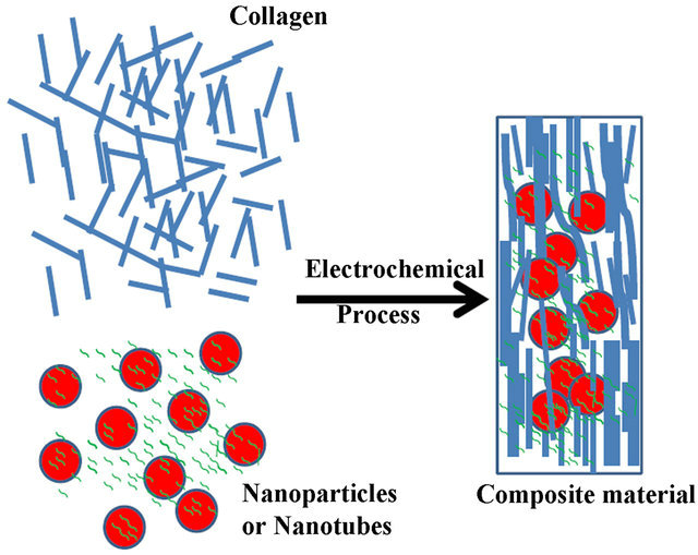
Figure 1. Schematic electrochemical encapsulation of Nanomaterials or biomolecules inside collagen to form materials with novel mechanical, electric, magnetic, and antimicrobial properties.
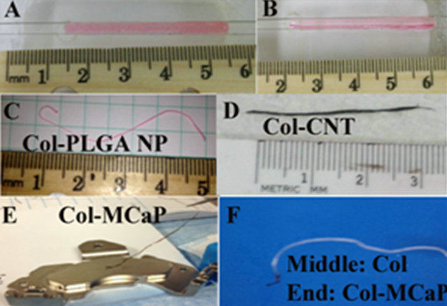
Figure 2. Electrochemical encapsulation of Nanomaterials inside collagen to form fibers. (A), (B) Collagen and dyeloaded NPs before and after electrochemical process; (C) Col-PLGA NP fiber; (D) Col-CNT fiber; (E) Magnetic ColMCaP fiber; (F) A fiber with the middle made from pure collagen and both ends made from Col-MCaP.
2.5 voltage was applied between two electrodes for 5 min, a Col-PLGA NP fiber was formed close to the cathode side (Figures 2(B) and (C)). Similarly, washed and dispersed single wall carbon nanotubes (CNTs, Outer diameter: ~1.5 nm, Length: 1 - 5 μm, Nanolab Inc., Waltham, MA) were mixed with dialyzed collagen, and subjected to the same electrochemical encapsulation process to form Col-CNT fiber (Figure 2(D)). Magnetic calcium phosphate (MCaP) NPs were prepared using our previously described procedure [8] and used to prepare ColMCaP fiber (Figure 2(E)). Moreover, by putting pure dialyzed collagen in the middle and Col-MCaP mixture in both ends of the electrochemical chamber, we formed a fiber with three different compositions, i.e., the middle was composed of collagen, and either end was composed of collagen-MCaP (Figure 2F).
2.2. Fabrication of Collagen Sheets Encapsulating, PLGA-m-PEG NPs, Chitosan/Silver, MCaP NPs, CNTs
The experimental set up to form collagen-based sheet was shown in Figure 3(A). The electrodes used are stainless steel (anode) and Pt (cathode) sheets. Each ColNano/bio material mixture was filled inside the chamber and similar voltage was applied to form different sheets (Figures 3(B)-(F)). In the end, each sheet was deposited on the platy cathode due to high basic pH on the cathode side.
For preparation of Col-Chitosan-Ag sheet, a two-step special procedure was used as described previously [9]. First, Chitosan was added to acidic collagen (3 mg/
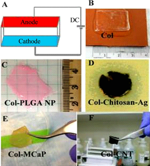
Figure 3. Electrochemical encapsulation of Nanomaterials inside collagen to form multifunctional sheets. (A) Electrochemical chamber set up; (B) Pure Col sheet, (C) Col-PLGA NP sheet; (D) Antimicrobial Col-chitosan-nanosilver sheet; (E) Magnetic Col-MCaP sheet; (F) Col-CNT sheet.
mL, Devro Medical Inc.) solution at 2% concentration and form a circular sheet using the electrochemical process. Then Chitosan-collagen sheets were placed inside 1% glutaraldehyde for mild crosslinking and introduction of aldehyde pending groups. Then they were placed in silver nitrate solution for silver deposition to form ColChitosan-Ag sheets.
2.3. Electric Conductivity Measurement and Mechanical Testing of CNT-Collagen Fiber
Electrical conductivity of the dried collagen-CNT fibers were studied by the electrical impedance spectroscopy (EIS) and direct DC methods at room temperature. The assembled instrumentation involves two spring contacted gold spheres attached to two separate micro-manipulators mounted on an optical breadboard with a wafer holding stage and connected to either a BAS Zhaner IM6 impedance analyzer or multimeter.
Col fibers and Col-CNT fibers were both tested to determine their tensile mechanical properties. Both ends of dried bundles were fixed between thin PVC tabs using cyanoacrylate and the bundles were rehydrated in phosphate-buffered saline. Prior to testing, rehydrated specimen thickness was measured using a calibrated digital microscope (VHX-100, Keyence Corp., Elmwood Park, NJ). Specimens were also photographed using the digital microscope in order to determine the initial distance between PVC tabs and to determine specimen width at the approximate point of failure following testing. Specimens were mounted in a screw-driven electromechanical testing frame (Insight, MTS Systems Corp, Eden Prairie, MN), and loaded monotonically under displacement control (10 mm/min.) to tensile failure. Crosshead displacement was measured using the testing frame LVDT and load was measured using a 5 lb. (22.24 N) load cell (Transducer Techniques, Temecula, CA). After testing, specimen width was determined from the calibrated photographs at the approximate point of failure. In order to account for any slack in the specimens prior to testing, initial specimen length was determined as the sum of the distance between PVC tabs and the displacement at the point when tensile load was registered. Specimen strain was determined by dividing displacement data by initial specimen length and stress was determined by dividing load data by the cross-sectional area calculated as the product of specimen thickness and width at the point of failure. Specimen modulus was determined as the steepest slope in the stress-strain data using a moving window approach. Maximum tensile stress and strain at the point of maximum tensile stress were also determined. Nonparametric Wilcoxon rank-sum tests were used to evaluate the statistical significance of differences between modulus and peak stress for the Col and Col-CNT fiber bundles.
2.4. Antimicrobial Testing of Col-Chitosan-Ag Sheet
The antimicrobial test was conducted to compare the zone of inhibition (ZOI) of chitosan disks on two bacterial strains, Staphylococcus aureus (gram positive) and Pseudomonas aeruginosa (gram negative). Kirby Bauer Disk Diffusion method was used to determine the ZOIs on large (15 cm) Mueller Hinton agar plates. The inoculated plates were allowed to dry for 15 min. Col-Chitosan-Ag disks were placed at the center of agar plates. The plates were then inverted and incubated for 24 hours at 37˚C. The clear area surrounding the disks represents the antibiotic activity and is called ZOI. After 24 hours the diameter of ZOIs were measured in millimeters. The tests were conducted in duplicates.
2.5. Attachment and Proliferation of Neuron Progenitor Cells (NPCs) on Col-CNT Fiber
Col and Col-CNT fibers were removed from 70% ethanol solution and washed in [N2] medium, a modified version of neurobasal medium containing B27 and N2 supplements to remove any excess ethanol. Using a dissecting microscope, the fibers were then placed into a 35 mm culture dish which has been coated with a thin layer of inert vacuum grease. This was necessary in order to assure that the fibers do not move during testing period and to prevent floating. Glass weights were placed on the edges of the fibers as an additional preventative measure. Fibers were then seeded with mouse neural progenitor cells (NPCs). NPCs had been previously derived from mouse cells using the stromal cell derived factor method [10]. These cells were also genetically modified to express GFP using lentivirus pWPXL-GFP [11]. The derivation of the cell line and the genetic modification were performed in Dr. Hornsby’s lab (unpublished observations). Cells were grown for four days and photographed via fluorescence microscopy on days 2, 3, and 4. The presence of green fluorescent protein was required for cell viewing. CNTs are black and when combined with clear collagen, a black fiber was formed and phase contrast cannot be used to view the cells. Thus imaging of the cells on the surface of the Col-CNT fibers cannot be achieved unless the cells are fluorescent. This requires the presence of GFP expressing cells and the use of a fluorescence microscope for viewing.
2.6. Enhanced Proliferation of Adipose-Derived Stem Cells (ADSCs) from PDGF-Loaded Col-PLGA NP Fibers
ADSCs derived from Lewis rats were provided frozen from Dr. Robert Christy at the US Army Institute of Surgical Research (USA ISR) using an approved protocol. Cells were thawed and placed in a T-75 culture flasks with MesenPRO RSTM Medium and Growth Supplement, HBSS, L-glutamine 200 mM and antimycotics (all Invitrogen). MesenPRO RSTM Medium is a reduced serum (2%) medium specifically formulated to support the growth of human mesenchymal stem cells (MSCs) in culture. Using MesenPRO RSTM Medium, MSCs can be expanded for multiple passages while maintaining their multipotential phenotype (i.e., differentiation into osteogenic, chondrogenic, and adipogenic lineages). Cells were incubated and passed twice into T-75 flasks with media.
Two different types of Col-NP fibers were placed inside 6-well cell culture plates (N = 3 per well). In the control group, the PLGA NPs have no PDGF loaded. In the experimental group, NPs were loaded with PDGF. Each plate was seeded with ~89,500 Passage 2 cells and returned to the incubator. After 7 days of incubation, both control fibers and experiment fibers were removed and stained with 4 drops of NucBlueTM (Life Technologies) nucleus stain. Substrates were placed on a Nikon Eclipse TE2000-S fluorescent microscope and imaged with a 20× objective with NIS-Elements BR (v3.00) software. A UV dicrotic mirror was used to observe cell nuclei. Four observations were conducted per fiber (3 fibers per well). After live cell counts were complete, cells were then fixed with glutaraldehyde, stained with DAPI (D3511, Lot 983827, Invitrogen) and Palloidin Alexa Flour 488 (A12379-3000U, Lot 808465, Invitrogen) and viewed with a FITC filter. Images were taken on an Olympus IX81 inverted fluorescence microscope with a halogen light source and an Olympus DP72 camera.
3. Results
3.1. Fabrication of Collagen Fibers Encapsulating PLGA-m-PEG NPs, Carbon Nanotubes, Magnetic Calcium Phosphate NPs
Figures 2(A) and (B) demonstrated the electrochemical encapsulation process to form Col-PLGA NP fiber. Due to loading of rhodamine 6G dye inside PLGA-m-PEG NPs, the NPs suspension appeared red. The Col-PLGA NP mixture appeared uniform red between two wire electrodes (Figure 2(A)). After applying 2.5 DC voltage between two electrodes for only 5 min., the Col-PLGA NP mixture already turned into a fiber lying close to the cathode side. The fiber appeared red color, while the rest of electrochemical chamber appear only slightly red, indicating that most of NPs were incorporated inside collagen fiber. The Col-PLGA NP fiber was collected and shown in Figure 2(C). Similarly, Col-CNT fiber (Figure 2(D)) appeared black due to incorporation of CNTs (up to 30% by wt% as measured by thermogravemetric analysis, data not shown). Col-MCaP fiber appears brown due to incorporation of yellow MCaP NPs. The magnetic property of Col-MCaP fiber was evident by the attraction of fiber by a permanent magnet (Figure 2(E)). To mimic the tendon/ligament to bone junctions, a composite fiber (Figure 2(F)) was formed, where the middle part was composed of collagen, while the end (brown color) was composed of Col/MCaP.
To further verify the loading of NPs inside collagen, two different Col-PLGA NP fibers were viewed by both optical microscope and fluorescence microscope. One fiber was formed by using rhodamine dye-loaded PLGA NPs (red arrow, Figure 4(A)), another fiber was formed using only empty PLGA NPs (white arrow, Figure 4(A)). As shown in Figure 4(A), both fibers are visible on the optical microscope. However, only the Col-PLGA NP fiber which was loaded with dye was visible using a fluorescence microscope (Figure 4(B), red arrow).
3.2. Fabrication of Collagen Sheets Encapsulating, PLGA-m-PEG NPs, Chitosan-Silver NPs, Magnetic CaP NPs and CNTs
In a similar way, collagen sheets encapsulating various Nanomaterials or biomolecules were shown in Figures 3(B)-(F). Compare to transparent pure collagen sheet (Figure 3(B)), the Col-PLGA NP sheet appeared red due to the loading of rhodamine dye inside PLGA NPs (Figure 3(C)). On the other hand, the Col-chitosan-Ag sheet appeared brown due to deposition of nano silver (Figure 3(D)) [8]. A clear zone of inhibition against Pseudomonas aeruginosa was shown on agar plate due to its antimicrobial activities. Similarly to the fibers, the Col-MCaP sheet and Col-CNT sheet appeared brown and black (Figures 3(E) and (F)), respectively.
3.3. Electric Conductivity Measurement and Mechanical Testing of CNT-Collagen Fiber
The electronic behavior of the Col-CNT composite fibers was characterized using EIS and also with a standard voltmeter. Figure 5 shows EIS Nyquist plot of a ColCNT fiber. Despite that collagen is an electrical insulator,
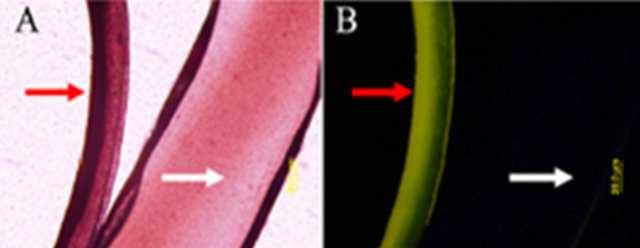
Figure 4. Confirmation of NP loading inside collagen fibers using optical microscope and fluorescence microscope. (A) Optical images of Col-PLGA NP fiber one fiber (red arrow) was loaded with dye, while the other only has empty NPs (control, white arrow); (B) Fluorescence image of fiber.
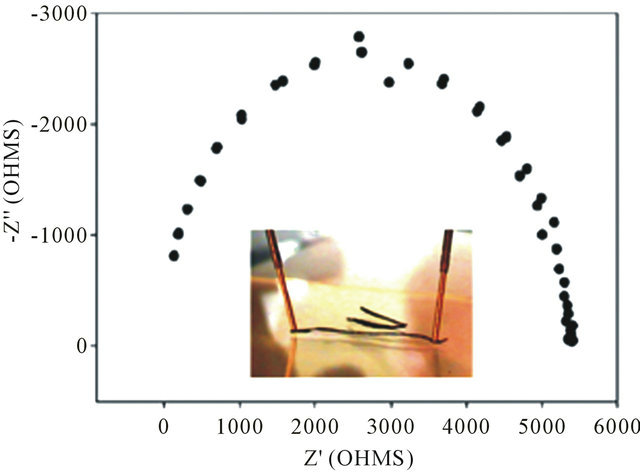
Figure 5. EIS Nyquist plot of a Col-CNT fiber. Inset shows photograph of electrical measurement. DC resistance measured with a probe distance of 9 mm was 135 Ω.
the Col-CNT fibers were electrically conductive. DC resistance measured with a probe distance of 1 cm was 135 Ω. Based on their conductivity, Col-CNT fibers could aid in cell growth and differentiation with electrical stimulation and be used for nerve applications.
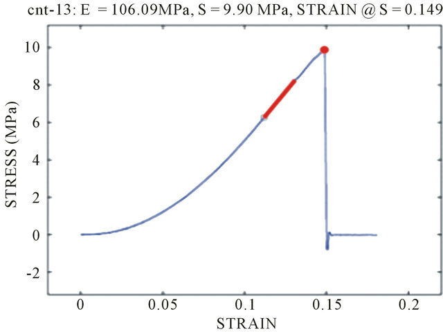
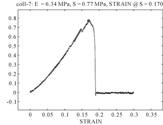
Typical stress strain curves for Col-CNT fiber and collagen fiber are shown in Figure 6. The mechanical properties (tensile strength) of the Col-CNT were evidently superior to those of the counterpart pure Col fibers. The Col-CNT fibers exhibited a 15-fold increases in modulus and a 13-fold improvement in tensile strength as compared to collagen control fibers (Figure 6).
3.4. Antimicrobial Testing of Col-Chitosan-Ag Sheet
Due to encapsulation of chitosan which is enriched with amine groups, silver NPs can be deposited onto ColChitosan sheet to form Col-Chitosan-Ag. The resultant sheet successfully inhibited two common strains of bacteria (Gram-positive and Gram negative, Figure 7). This novel Col-Chitosan-Ag sheet can be used as antimicrobial haemostatic wound healing product.
3.5. Attachment and Proliferation of NPCs on Col-CNT Fiber
Biocompatibility was tested by assessing the process of attachment and growth of NPCs. Col-CNT fibers were seeded with GFP-expressing NPCs. They were imaged on days 2, 3, and 4. Figure 8 above show the fibers as imaged on day on 4. The images indicated that the addition of CNTs did not affect the biocompatibility of the fibers and the cell growth was unhindered. Additionally, the cells seem to attach well onto the surface of the fibers. There was no evidence of the cells detaching and even though the fibers were subjected to some movement
(A)
(B)
Figure 6. Typical stress-strain curves of (A) a Col-CNT fiber and (b) a neat Col fiber (N = 5).

(A) (B)
Figure 7. Col-Chitosan-Ag sheet has broad-spectrum antimicrobial activities. ZOI against (A) S. aureus (gram positive) and (B) Peudomonas aeruginosa (gram negative).
when being turned over for cell imaging, the cells maintained their growth and attachment. The Col-CNT fibers displayed areas of alignment along the fiber. In these areas, cells were lined parallel to the fiber with neurite extensions reaching out towards one another. Overall the Col-CNT fiber showed excellent cell growth and attachment while displaying no toxicity while exhibiting areas of aligned cell growth with neurite extensions (Figure 8).
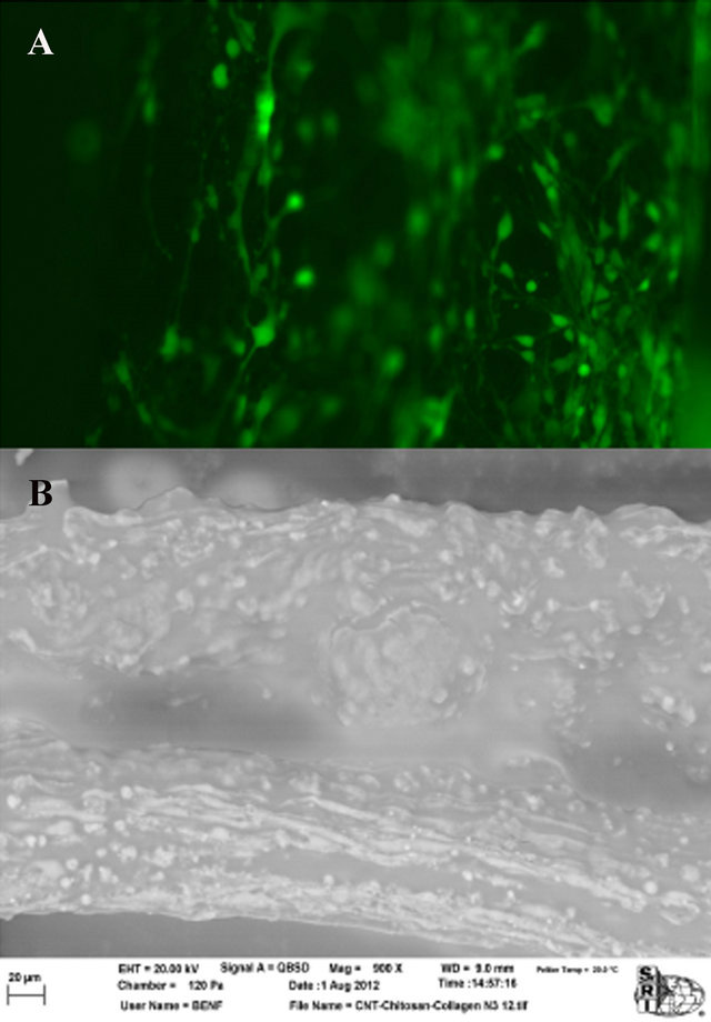
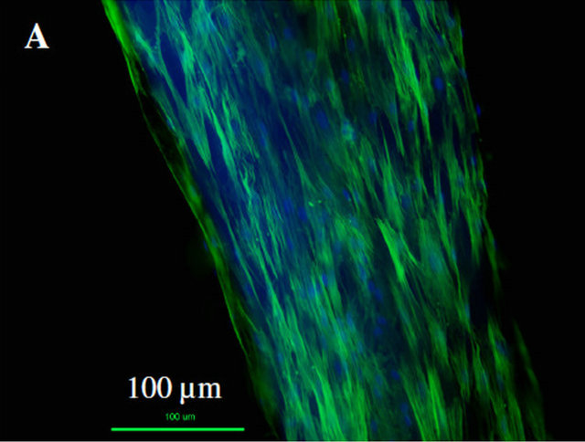
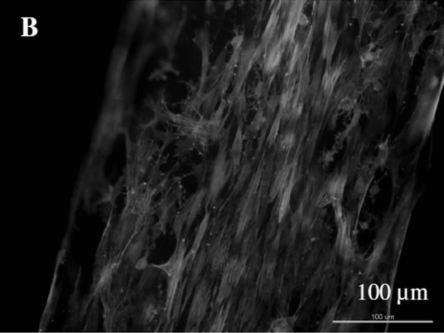
Figure 8. NPCs attached to the surface of Col-CNT fibers. (A) Fluorescence microscope image of GFP-expressing NPCs on Col-CNT fibers. Images were taken on day 4 of cell testing; (B) SEM image of NPCs on Col-CNT after osmium tetroxide staining. Bar = 20 µm.
3.6. Enhanced Proliferation of Adipose-Derived Stem Cells from PDGF-Loaded Col-PLGA NP Fibers
As shown in Figure 9, for both type of Col-NP fibers (PDGF and control), ADSCs can proliferate well on it. The cytoskeleton and nuclei of ADSCs were extended along the fiber direction due to the alignment of collagen fibers (Figures 9(A) and (B)). Live cell counting directly on aligned collagen-NP fibers indicated that there is significant increase in cell proliferation (at least 2 fold) on aligned collagen-NP fibers that contain PDGF than control (Figure 9(C)).
4. Discussion
We have demonstrated here a novel electrochemical encapsulation process which takes advantage of controlled co-assembly of collagen with a wide range of nanomaterials and biomolecules. For Nanomaterials, we have demonstrated CNTs, PLGA NPs, MCaP NPs can be encapsulated inside the collagen. For biomolecules, we

(C)
Figure 9. ADSC cell proliferation directly on two types of Col-PLGA NP fibers. (A)-(B) Composite fluorescence image of ADSCs on Col-PLGA NP fibers (control and PDGF); (C) Cell proliferation directly measured on top of the ColPLGA NP fibers (control and PDGF).
demonstrated that chitosan, and eventually silver can be encapsulated inside the collagen.
The advantage of the electrochemical process is as follows: 1) easiness of experimental set up; 2) the encapsulation process only involves water and low DC voltage, unlike other process which involve toxic solvents (e.g., Electrospinning); 3) most Nanomaterials can be encapsulated. Despite possibility of digestion of PLGA NPs at basic pH, we have demonstrated PLGA NPs can be encapsulated inside collagen, due to quickness of the encapsulation process. Finally, and most importantly, through encapsulation of various Nanomaterials and biomolecules, multifunctional collagen-based biomaterials (fibers and sheets) with improved electric, mechanical, antimicrobial, magnetic properties can be formed.
A convincing example is the Col-CNT fiber. Due to incorporation of a large amount of CNTs (up to 33%) using this process, the dried fiber is electrically conductive. On the other hand, Col fiber itself is not. We also showed the modulus, tensile strength of Col-CNT is superior to those of pure Col fiber, without any crosslinking. NPC can attach and grow well on these fibers. Thus, these Col-CNT fibers have potential to be used as neuron interface materials, tendon/ligament grafts, etc.
Another example is formation of magnetic Col-MCaP fibers and sheets. We have previously showed that MCaP NPs can be remotely heated up (e.g., 42˚C) using alternating magnetic field [8]. As an implantation materials, the Col-MCaP fiber or sheets offers a new means to change the cell and tissue behavior through local change of temperature. For example, Col-MCaP sheets might be used as a wound dressing while acts as a “magnetic thermo blanket”. Similarly, pure Col sheet and antimicrobial Col-chitosan-Ag are a promising wound dressing material [12]. On the other hand, the biphasic fiber with two different compositions, i.e., the middle was composed of collagen, and either end was composed of collagen-MCaP, has great potential to be used as an engineering orthopedic interfacing material (e.g., tendon/ ligament/bone junction) [13,14].
Finally, we demonstrated by loading drugs/growth factors such as PDGF inside Col-PLGA NP fiber, the proliferation of ADSCs was significantly enhanced (Figure 9).
5. Conclusion
In summary, we have demonstrated a novel encapsulation technique/method, i.e., electrochemical encapsulation process. By changing electrode configuration and electrochemical chamber set up, a wide range of Nanomaterials (e.g., CNTs, PLGA NPs, MCaP NPs) and biomolecules (Chitosan, silver) can be encapsulated and formed into fibers or sheets. Through encapsulation of these Nanomaterials and biomolecules inside collagen, collagen-based biomaterials with improved electric, magnetic, mechanical, antimicrobial, and bioactive properties can be formed. The electrochemical encapsulation process provides us an effecitve means to fabricate novel collagen-based composite nano/biomaterials for various biomedical applications.
6. Acknowledgements
The authors gratefully acknowledge support of this work from the Southwest Research Institute® (SwRI®) Internal Research and Development (IR&D) Program and funding from US ARMY MED RESEARCH ACQ ACTIVITY (Contract No. W81XWH-10-1-0986). We would also like to thank Professor Bingyun Li for his help with antimicrobial testing of Col-chitosan-silver sheet. In addition, support of Professor Victor Sylvia and Douglas Cornet (a Ph.D. candidate) at University of Texas Health Science Center at San Antonio in conducting the ADSCs proliferation and imaging study and Dr. Robert Christy at USA ISR in providing the ADSCs are greatly appreciated. Finally, we want to thank Dr. Peter Hornsby at University of Texas Health Science Center for his help in the NPC experiment.
REFERENCES
- V. Ottani, M. Raspanti and A. Ruggeri, “Collagen Structure and Functional Implications,” Micron, Vol. 32, No. 3, 2001, pp. 251-260. doi:10.1016/S0968-4328(00)00042-1
- L. Cen, W. Liu, L. Cui, W. J. Zhang and Y. L. Cao, “Collagen Tissue Engineering: Development of Novel Biomaterials and Applications,” Pediatric Research, Vol. 63, No. 5, 2008, pp. 492-496. doi:10.1203/PDR.0b013e31816c5bc3
- O. Akkus, A. Panitch and X. G. Cheng, “Aligned Collagen and Method Therefor,” International Patent Application No. PCT/US2008/084958, 2009.
- X. G. Cheng, U. A. Gurkan, C. J. Dehen, M. P. Tate, H. W. Hillhouse, G. J. Simpson and O. Akkus, “An Electrochemical Fabrication Process for the Assembly of Anisotropically Oriented Collagen Bundles,” Biomaterials, Vol. 29, No. 22, 2008, pp. 3278-3288. doi:10.1016/j.biomaterials.2008.04.028
- X. G. Cheng and C. Tsao, “Delivery Substrates from Aligned Polymer Biomaterials for Tissue Repair,” US Patent No. 61/730261, 2012.
- X. G. Cheng and S. Desai, “Preparation of NanoparticleContaining Aligned Collagen Fibers for Dense Connective Tissue Repair and Regeneration,” MRS Conference Proceedings, Cambridge Journals Online, Vol. 1417, 2012, p. 5.
- X. G. Cheng and V. Poenitzsch, “Aligned Polymers Including Bonded Substrates,” US Patent No. 12/813834, 2010.
- X. G. Cheng, Q. W. Ni and T. Potter, “Magnetic Calcium Phosphate Nanoparticles, Applications and Methods of Preparation Thereof,” US Patent No. 13/568644, 2012.
- X. G. Cheng, “Development of Amorphous NanosilverChitosan-Collagen Biomaterial as an Antimicrobial Haemostatic Wound Healing Dressing,” Proceedings of 2011 MRS Fall Meeting, Boston, 2011.
- H. Kawasaki, K. Mizuseki, S. Nishikawa, S. Kaneko, Y. Kuwana, S. Nakanishi, S. I. Nishikawa and Y. Sasai, “Induction of Midbrain Dopaminergic Neurons from ES Cells by Stromal Cell-Derived Inducing Activity,” Neuron, Vol. 28, No. 1, 2000, pp. 31-40. doi:10.1016/S0896-6273(00)00083-0
- R. Zufferey, J. E. Donello, D. Trono and T. J. Hope, “Woodchuck Hepatitis Virus Posttranscriptional Regulatory Element Enhances Expression of Transgenes Delivered by Retroviral Vectors,” Journal of Virology, Vol. 73, No. 4, 1999, pp. 2886-2892.
- X. G. Cheng, A. Ben and J. Ling, “Electrochemical Aligned Collagen Sheet Cultured with Mesenchymal Stem Cells (MSCs) for Potential Skin Tissue Regeneration Applications,” Tissue Engineering and Regenerative Medicine (Termis) Conference, Houston, 18-21 December 2011, p. 14.
- P. J. Yang and J. S. Temenoff, “Engineering Orthopedic Tissue Interfaces,” Tissue Engineering—Part B: Reviews, Vol. 15, No. 2, 2009, pp. 127-141.
- H. H. Lu, S. D. Subramony, M. K. Boushell and X. Zhang, “Tissue Engineering Strategies for the Regeneration of Orthopedic Interfaces,” Annals of Biomedical Engineering, Vol. 38, No. 6, 2010, pp. 2142-2154. doi:10.1007/s10439-010-0046-y