 Open Journal of Civil Engineering, 2013, 3, 29-44 http://dx.doi.org/10.4236/ojce.2013.31005 Published Online March 2013 (http://www.scirp.org/journal/ojce) The Compactions of Elasto-Plastic and Visco-Plastic Granular Assemblies Pengfei He, Yuching Wu, Huiliang Chen College of Civil Engineering, Tongji University, Shanghai, China Email: ycwu@tongji.edu. cn Received November 16, 2012; revised December 18, 2012; accepted December 30, 2012 ABSTRACT In this paper, the compactions of the elasto-plastic and the visco-plastic granular assemblies are simulated using the finite element method. Governing equations for motion and deformation for particles, including coupling of rigid body motion and deformation for deformable bodies, are investigated. An implicit discrete element method for block systems is developed to make visco-plastic analysis for the assemblies. Among particles, three different contact types, cohering, rubbing and sliding, are taken into account. To verify accuracy and efficiency of the numerical method, some numerical example is simulated and the results are in a satisfactory agreement with the solutions in literatures. The effects of fric- tional condition , the initial solid volume ratio, the number of particles in the assembly, and different types of co mpact- tion on the compaction of the elasto-plastic and the visco-plastic aggregates are investigated. It is demonstrated that the effect of frictional condition, the initial solid volume ratio, the number of particles in the assembly, and different types of compaction on the global behavior of the elasto-plastic the visco-plastic granular assemblies under compacting are considerable. The numerical model is extended to simulate the compaction of aggregates consisting of mixed particles of different viscous incompressible materials. It is indicated that, with minor modification, the method could be used in a variety of problems that can be represented using granular media, such as asphalt, polymers, aluminum, snow, food product, etc. Keywords: Compaction; Elasto-Plastic; Visco-Plastic; Granular Assembly; Finite Element Method 1. Introduction Researches focused on particulate materials were devel- oped rapidly in the past 20 years. In the 1990s, basic physics of particle material characteristics were de- scribed in detail by Jaeger and Nagel [1], and fundamen- tal theory of mechanics of granular materials was devel- oped. At the same time, the load distribution for two- dimensional aggregates compaction was studied by Lud- ing [2]. For the issue of the particle shape, two-dimen- sional quasi-static analysis for circular particle compres- sion state was made by Bashir and Goddard [3]. The fric- tional pressure of oval particles was taken into accoun t in theoretical analysis and numerical simulation by Tzafer- opoulos [4]. Coppersmith et al. [5] studied the problem of bead-like particles model. Matuttis [6] simulated two- dimensional hexagonal particle under distributed loading. Satake [7] presented a random distribution method to define particle position based on theoretical and numeri- cal analysis. Emeriault et al. [8] proposed a uniform method to create a structure consisting of the oval-shaped particles. Antony et al. [9] investigated limit state of compression and impact of aggregates consisting of the flat round, round and elong ated spherical particles. I t was demonstrated that the effect of particle shape on the final result was little. The same particle samples under differ- ent pressure distribution were studied. In the final state of compression of the particles, it was indicated that the shape and distribution of particles had little effect on the global elastic deformation resulted from rigid body movement of particles. In addition, some scholars have begun to investigate compaction of particles of non-spherical shape. Wu [10] simulated compaction of adhesive polygonal particles in different size. A step-by-step incremental numerical model was developed to simulate the compaction of granular system of non-spherical nonlinear visco-plastic particles. The nonlinear visco-plastic constitutive law of each particle was derived based on the generalized Maxwell model that the material property of each ele- ment was treated as a series connection of a linear elastic matter to the other nonlinear visco-plastic media. The mesh upgrade scheme, consisting of contact detection algorithms, mesh update algorithms, concave four-node element modification, and locking preven tion subroutine, was generated based on a mixed triangular and quadric- C opyright © 2013 SciRes. OJCE 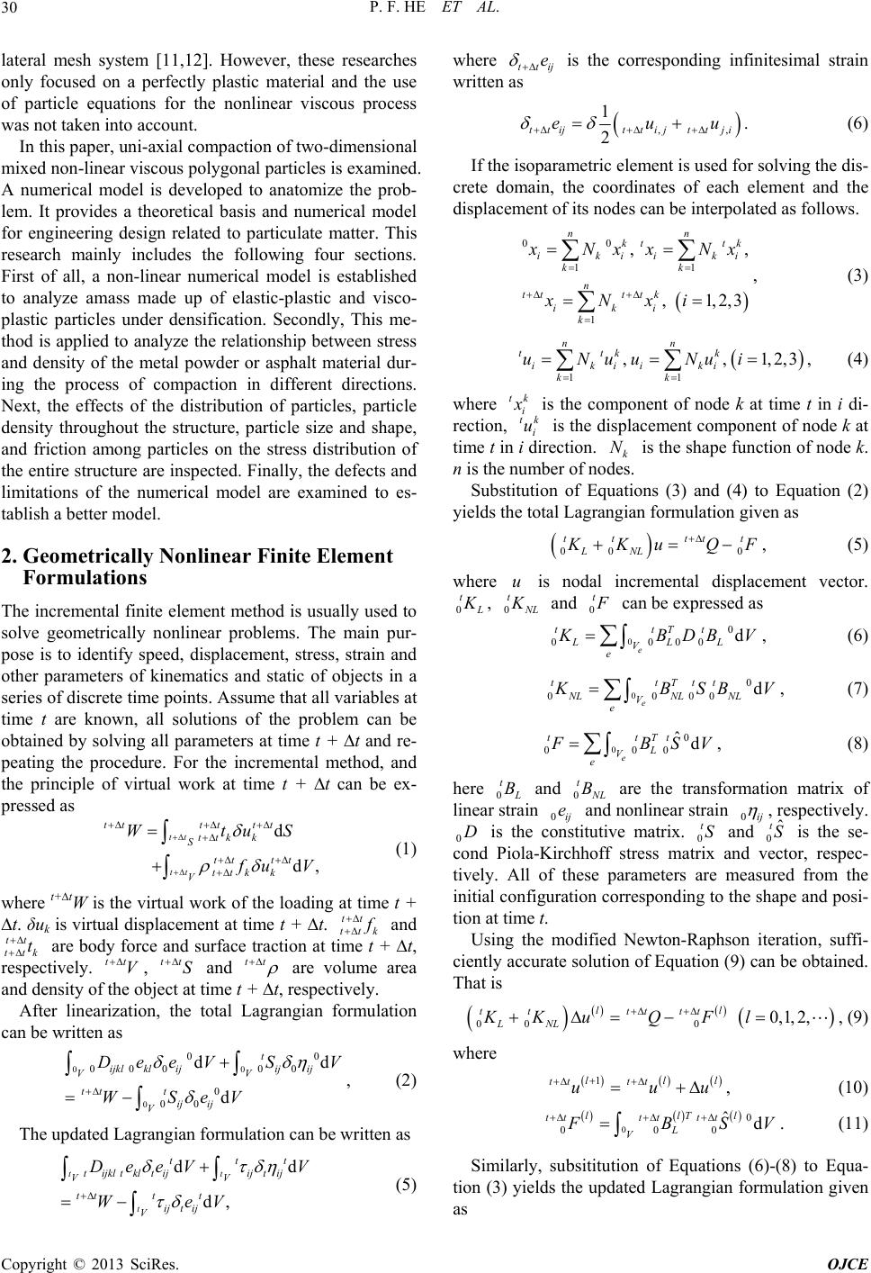 P. F. HE ET AL. 30 lateral mesh system [11,12]. However, these researches only focused on a perfectly plastic material and the use of particle equations for the nonlinear viscous process was not taken into account. In this paper, uni-axial compaction of two-dimensional mixed non-linear v iscous po lygon al particles is ex amined. A numerical model is developed to anatomize the prob- lem. It provides a theoretical basis and numerical model for engineering design related to particulate matter. This research mainly includes the following four sections. First of all, a non-linear numerical model is established to analyze amass made up of elastic-plastic and visco- plastic particles under densification. Secondly, This me- thod is applied to an alyze the relationship between stress and density of the metal powder or asphalt material dur- ing the process of compaction in different directions. Next, the effects of the distribution of particles, particle density throughout the structure, particle size and shape, and friction among particles on the stress distribution of the entir e structure a re inspected. Finally, the defects and limitations of the numerical model are examined to es- tablish a better model. 2. Geometrically Nonlinear Finite Element Formulations The incremental finite element method is usually used to solve geometrically nonlinear problems. The main pur- pose is to identify speed, displacement, stress, strain and other parameters of kinematics and static of objects in a series of discrete time points. Assume that all variables at time t are known, all solutions of the problem can be obtained by solving all parameters at time t + t and re- peating the procedure. For the incremental method, and the principle of virtual work at time t + t can be ex- pressed as d d, tt k k tttt ttk k uS tt tt tt tt tt S V Wt uV tt (1) where t+tW is the virtual work of th e loading at time t + t. δuk is virtual displacement at time t + t. tt k tt and tt t k tt V S are body force and surface traction at time t + t, respectively. , and tt tt are volume area and density of the object at time t + t, respectively. After linearization, the total Lagrangian formulation can be written as 0 0 00 0 0 00 d ijkl kl ij V tt t ij ij V DeeV WSe 0 00 00 dd t ij ij V S V V dd d, t ttt ij t ij V V V ij e , (2) The updated Lagrangian formulation can be written as t t tijkltkltij V ttt t ijt ij V DeeV We (5) where tt is the corresponding infinitesimal strain written as ,, 1 2 ttijttij ttji euu 00 11 1 ,, ,1,2,3 nn kt tk ikiiki kk n tt ttk iki k . (6) If the isoparametric element is used for solving the dis- crete domain, the coordinates of each element and the displacement of its nodes can be interpolated as follows. Nx xNx xNxi 11 ,,1,2,3 nn ttk k ikiiki kk uNuuNui tk i , (3) , (4) where is the component of node k at time t in i di- rection, i is the displacement component of node k at time t in i direction. k is the shape function of node k. n is the num ber of nodes. tk u N Substitution of Equations (3) and (4) to Equation (2) yields the total Lagrangian formulation given as 00 0 tt ttt LNL Ku QF u 0 t , (5) where is nodal incremental displacement vector. 0 t0 t , L and can be expressed as 00 0000 d e ttTt LLL V e BDB V 00 0000 d e ttTtt NLNL NL V e , (6) BSB V 00 000 ˆd e ttTt L V e , (7) BSV t , (8) here 0 B0 t and L are the transformation matrix of linear strain 0ij and nonlinear strain 0ij B e , respectively. 0 is the constitutive matrix. 0 and 0 is the se- cond Piola-Kirchhoff stress matrix and vector, respec- tively. All of these parameters are measured from the initial configuration corresponding to the shape and posi- tion at time t. DtSˆ tS Using the modified Newton-Raphson iteration, suffi- ciently accurate solution of Equation (9) can be obtained. That is 000 0, 1,2, ll tttt tt LNL KKuQ Fl 1lll tt tt uuu 00 000 ˆd llTl tttt tt L V , (9) where , (10) BSV . (11) Similarly, subsititution of Equations (6)-(8) to Equa- tion (3) yields the updated Lagrangian formulation given as Copyright © 2013 SciRes. OJCE 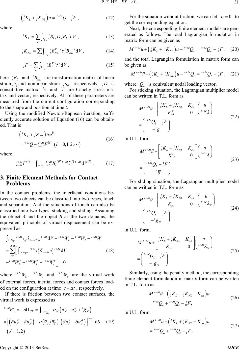 P. F. HE ET AL. 31 tt tL tNL ttt t Ku QF d Ttt LttL , (12) where te tt tL t V e BDB V d Tttt NL tNL , (13) te tt tNLt V e BBV 0ˆd e tTtt tL V t , (14) t e BV t t tL B B , (15) here and t tNL are transformation matrix of linear strain tij and nonlinear strain ij e , respectively. t is constitutive matrix. t D and tˆ are Cauchy stress ma- trix and vector, respectively. All of these parameters are measured from the current configuration corresponding to the shape and pos ition at time t. Using the modified Newton-Raphson iteration, suffi- ciently accurate solution of Equation (16) can be obtain- ed. That is tL tNL l tttt tt KK QF 0, 1,2, l tt u l ˆd llTll tttttt tt (16) where tt tt ttL V BV d tttttttt tt I c eVWWW . (17) 3. Finite Element Methods for Contact Problems In the contact problems, the interfacial conditions be- tween two objects can be classified into two types, touch and separation. And the situations of touch can also be classified into two types, sticking and sliding. Assuming the object A and the object B as the two domains, the equivalent principle of virtual displacement can be ex- pressed as ,d 0 tt ttr ij ttijL V AB ttr rtt ijttij V r tt rtt rtt r LI c eV WWW tt (18) where W tt , W c W and tt are the virtual work of external forces, inertial forces and contact forces load- ed on the configuration at time , respectively. tt If there is friction between two contact surfaces, the virtual work is expresse d as 1, 2 tt c cC P NN S AB NNJT J uu uu u J d ttAB t NN tt AB J Wuug u S 0 (19) For the situation without friction, we can let to get the corresponding equation. Next, the corresponding finite ele ment models are gen- erated as follows. The total Lagrangian formulation in matrix form can be given as 00 0 tt ttttttt LNLc L uK KuQQF , (20) and the total Lagrangian formulation in matrix form can be given as tt ttttttt tL tNLcL t uK KuQQF , (21) where Q is equivalent nodal loading vector. For sticking situation, the Lagrang ian multiplier model can be written in T.L. form as 00 0 0 tt tt LNLc tt T c tt t L t u KKK Mu K QF g (22) in U.L. form, 0 tt tt tL tNLc tt T c tt t Lt t u KKK Mu K QF g (23) For sliding situation, the Lagrangian multiplier model can be written in T.L. form as 00 0 0 , tt tt LNLc tt N cu tt t L t N u KKK Mu K QF g (24) in U.L. form, 0 . tt tt tL tNLc tt N cu tt t Lt t N u KKK Mu K QF g (25) Similarly, using the penalty method, the corresponding finite element formulation in matrix form can be written in T.L. form as 00 0, tt tt LNLc tt ttt Lc uKKKu QQF (26) in U.L. form, , tt tt tL tNLc tt tt t Lct uK KKu QQF (27) Copyright © 2013 SciRes. OJCE  P. F. HE ET AL. 32 where 1 1 c cc k n tt tt cc k KK QQ 1 ,, . cc nn cc kk k k uu (28) 4. Verification Compaction of the rigid elliptical particles has been si- mulated by Tzaferopoulos [4]. In this section, one of his numerical examples is simulated using the present nume- rical model. Results of both models are in a satisfactory agreement. The finite element mesh of the numerical example is presented. Since in the original literatu re particles are set to be of rigid body. The elastic modulus in the numerical model is set as 2 × 10¹⁰ MPa, and Poisson’s ratio 0.5. At the same time, the friction coefficient of contacts among 25 particles is set to be 0.1. Relation of particles to the surrounding rigid surface is set as contact state. The boundaries on the side and the bottom are fixed. The boundary on the top goes down in uniform velocity until it can not continu e going down. Final configurations from the present numerical model and literature are shown in Figure 1. It is indicated that final positions of particles are a little bit different be- tween two results. However, layout and location of parti- cles are very close to literature especially on the circled areas. It is demonstrated that the present numerical model is accurate and efficient. 5. Numerical Experiments In this section, first of all, elasto-plastic analyses of alu- minum granular materials are made using the proposed numerical model to get some properties of behavior of the aggregates in the compaction process. Next, visco- plastic analyses of asphalt aggregates are made to invest- tigate the global constitutive law. Then, mixed visco- (a) (b) Figure 1. Final configurations from (a) literature and (b) the present numerical model. plastic analyses for assembles of three types of asphalt are made to offer some reference data for asphalt Indus- try. 5.1. The Elasto-Plastic Analysis A series of elasto-plastic analyses of aluminum granular materials are made using the proposed numerical model to get some rules in the compaction process. The linear hardening elastic-plastic model is used as material model in the cases of temperature from 20˚C to 250˚C. It can be simplified to the ideal elastic-plastic model at tempera- ture higher than 250˚C. The stress-strain relation of alu- minum alloy at 250˚C is given in Table 1. In the elastic section elastic modulus is 64.1 GPa, and Poisson’s ratio 0.3. The compaction for two-dimensional assembly of 20 particles is simulated. The particles are placed on the border of 1 meter square in area. The initial grain bound- ary area is around 65% of the total area. The simulation is regarded as a plane strain calculation. The compactions of two-dimensional aggregates of twenty particles can be classified as three types, the lateral compaction, the ver- tical compaction, and the bi-axial compaction. Friction between particles and wall is neglected. The inward movement of walls is of 10 mm/s in velocity. Relation- ship of the wall pressure to solid ratio is obtained. 5.1.1. The Lateral Compaction In this simulation, the total loading time is set to be 40 s, with a total of 130 time steps. In the 124th step, the as- sembly is compacted to 98.43% of the initial area. The compaction process is shown in Figure 2. Figure 3 shows the relationship between the wall pres- sure and the solid ratio. The value of lateral pressure be- gins to increase when the solid ratio is about 0.77. A large increase in slope occurs when the solid ratio is close to 1. When the solid ratio is 98.43%, the average values of the left and right wall pressure is 290 MPa, and the one of the top and bottom wall pressure 224.8 MPa. For the same solid ratio, the left-right pressure is less than the up-down pressure. At the same time, it is shown that the curve is oscillated rather than smooth. It is re- sulted from the complex interaction among the particles. 5.1.2. The Vertical Com p action In this simulation, the total loading time is set to be 50 s, with a total of 170 time steps. In the 128th step, the as- sembly is compacted to 97.90% of the initial area. The Table 1. The stress-strain relation of aluminum alloy at 250˚C. Strain (%) 0 0.11 0.31 0.87 1.60 Stress (MPa)0 70.5 111.2 129.1 130.2 Copyright © 2013 SciRes. OJCE  P. F. HE ET AL. Copyright © 2013 SciRes. OJCE 33 Y (a) (b) Y (c) (d) Figure 2. The process of the lateral compaction at: (a) The first time step; (b) The 85th time step; (c) The 113th time step; (d) The 124th time step. Figure 3. The relationship between the wall pressure and the solid ratio.  P. F. HE ET AL. 34 compaction process is shown in Figure 4. Figure 5 shows the relationship between the wall pres- sure and the solid ratio. The value of lateral pressure be- gins to increase when the solid ratio is about 0.79. A large increase in slope occurs when the solid ratio is close to 1. When the solid ratio is 97.9%, the average values of the left and right wall pressure is 290.8 MPa, and the one of the top and bottom wall pressure 228.9 MPa. For the same solid ratio, the left-right pressure is less than the up-down pressure. At the same time, it is shown that the curve is os cillated rather than smooth. It is resulted from the complex interaction among the parti- cles. 5.1.3. The Biaxial Compaction In this simulation, the total loading time is set to be 40 s, with a total of 130 time steps. In the 89th step, the as- sembly is compacted to 99.37% of the initial area. The compaction process is shown in Figure 6. Figure 7 shows the relationship b etween the wall pres- sure and the solid ratio. The value of lateral pressure be- gins to increase when the solid ratio is about 0.79. A large increase in slope occurs when the solid ratio is close to 1. When the solid ratio is 99.3 7%, the values of the left wall pressure is 290.9 Mpa, the one of the right wall pressure is 309.9 MPa, the one of th e top wall pressure is 280.3 MPa, and the one of the bottom wall pressure is 297.2 MPa. For the same solid ratio, the left-right pres- sure is less than the up-down pressure. At the same time, it is shown that the curve is oscillated rather than smooth. It is resulted from the complex interaction among the particles. 5.2. The Visco-Plastic Analysis In this section, a series of visco-plastic analyses of as- phalt aggregates are made to investigate the global con- stitutive law. Here asphalt is used as the granular matter. Y Y (a) (b) YY (c) (d) Fi gu r e 4. T h e p r oc e s s of t h e v er t i c al c o m pa c t ion at: (a) The first time step; (b) The 82nd time st e p; ( c ) T h e 1 13 t h ti m e s te p ; (d) The 128th time step. Copyright © 2013 SciRes. OJCE 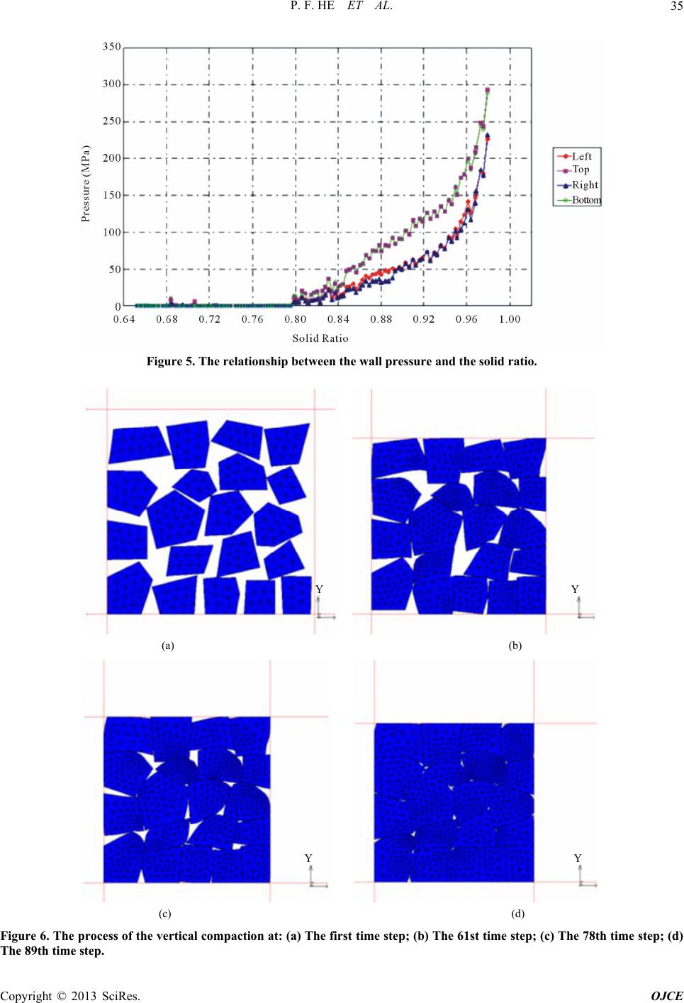 P. F. HE ET AL. 35 Figure 5. The relationship between the wall pressure and the solid ratio. YY (a) (b) YY (c) (d) Figure 6. The process of the vertical compaction at: (a) The first time step; (b) The 61st time step; (c) The 78th time step; (d) The 89th time step. Copyright © 2013 SciRes. OJCE  P. F. HE ET AL. Copyright © 2013 SciRes. OJCE 36 Figure 7. The relationship between the wall pressure and the solid ratio. Table 2. Parameters of the asphalt material properties. For the asphalt mixture, the visco-plastic strain is accu- mulated under cyclic loading. Generally, it is difficult to distinguish between visco-elastic and visco-plastic parts. And visc-oelastic properties can be changed under cyclic loading. Creep model is given as Creep Elastic A mn p q E/MPa 05.15 8 10 00.826 0 0.22 526 0.5 1ncmpq c Tqt . (29) large increase in slope occurs when the solid ratio is close to 1. When the solid ratio is 99.13%, the average values of the left and right wall pressure is 128.4 MPa, and the one of the top and bottom wall pressure 62.5 MPa. For the same solid ratio, the left-right pressure is less than the up-down pressure. Parameters of the asphalt material properties are listed in Table 2. Compaction for two-dimensional assembly of 16 par- ticles is simulated. The particles are placed on the border of 1 meter square in area. The initial grain boundary area is around 80% of the total area. The simulation is re- garded as a plane strain calculation. The compactions of two-dimensional aggregates of 16 particles can be classi- fied as three types, the lateral compaction, the vertical compaction, and the two-way compaction. Large deflect- tion and large strain are taken in to account in the process of the compaction. The large deflection and large strain operators are set in the calculation here. Meanwhile, to ensure the convergence of computation, all deformed meshes are generated adaptively. Friction between parti- cles and wall is neglected. The inward movement of walls is of 10 mm/s in velocity. Relationship of the wall pressure to solid ratio is obtained. 5.2.2. The Vertical Com p action In this simulation, the total loading time is set to be 43 s, with a total of 118 time steps. In the 55th step, the as- sembly is compacted to 99.19% of the initial area. The compaction process is shown in Figure 10. Figure 11 shows the relationship between the wall pressure and the solid ratio. The value of lateral pressure begins to increase when the solid ratio is about 0.86. A large increase in slope occurs when the solid ratio is close to 1. When the solid ratio is 99.19%, the average values of the left and right wall pressure is 162.7.4 MPa, and the one of the top and bottom wall pressure 97.5 MPa. For the same solid ratio, the left-right pressure is less than the up-down pressure. 5.2.1. The Lateral Compaction In this simulation, the total loading time is set to be 43 s, with a total of 118 time steps. In the 55th step, the as- sembly is compacted to 99.13% of the initial area. The compaction process is shown in Figure 8. 5.2.3. The Biaxial Compaction In this simulation, the total loading time is set to be 43 s, with a total of 197 time steps. In the 49th step, the as- sembly is compacted to 99.28% of the initial area. The ompaction process is shown in Figure 12. Figure 9 shows the relationship between the wall pres- sure and the solid ratio. The value of lateral pressure be- gins to increase when the solid ratio is about 0.86. A c 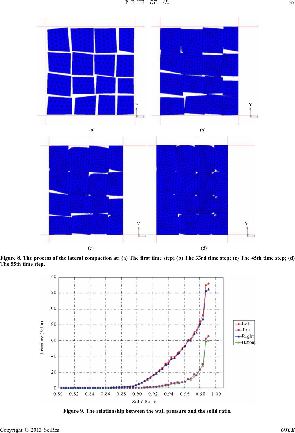 P. F. HE ET AL. 37 YY (a) (b) YY (c) (d) Figure 8. The process of the lateral compaction at: (a) The first time step; (b) The 33rd time step; (c) The 45th time step; (d) The 55th time step. Figure 9. The relationship between the wall pressure and the solid ratio. Copyright © 2013 SciRes. OJCE 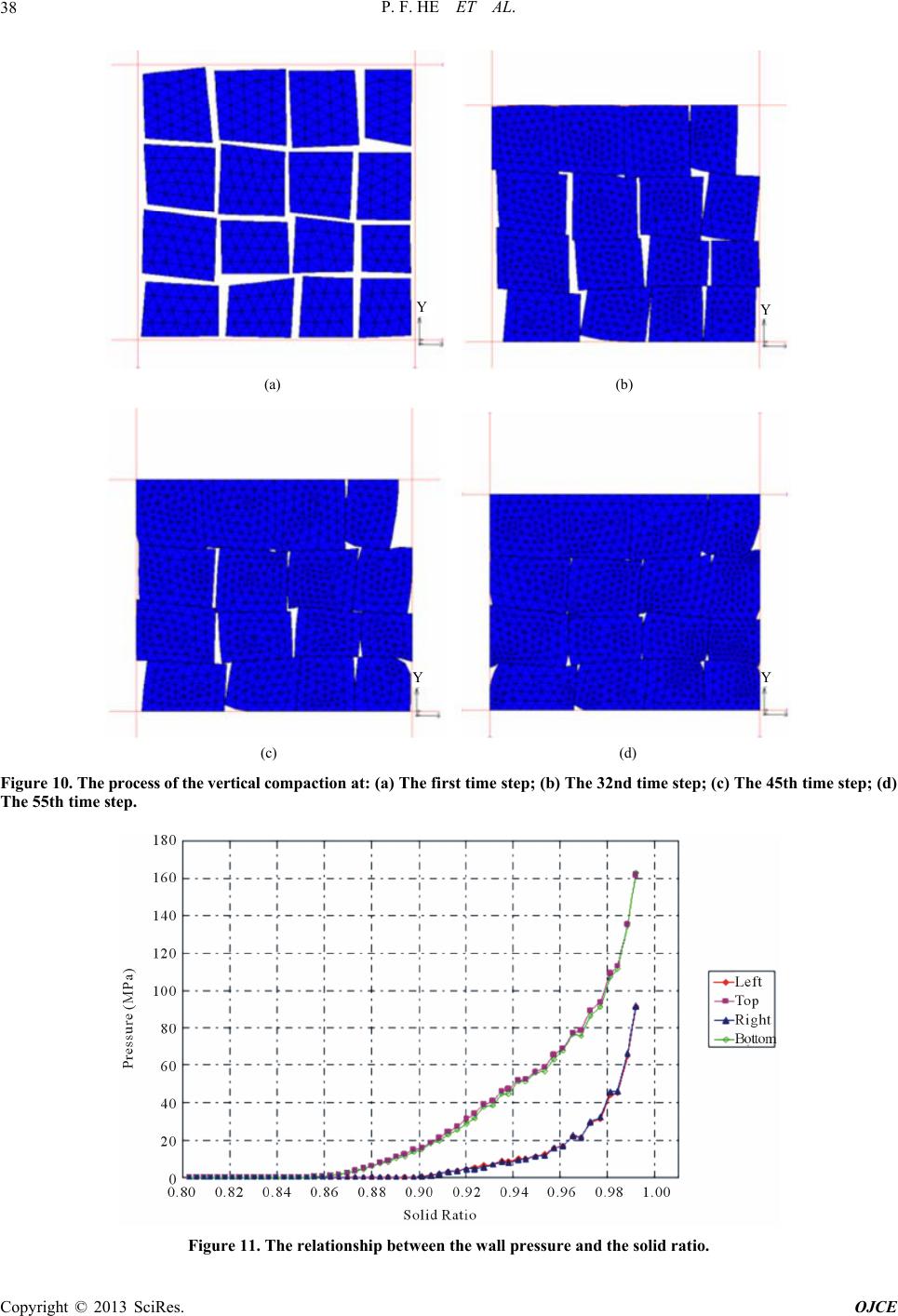 P. F. HE ET AL. 38 YY (a) (b) YY (c) (d) Figure 10. The process of the vertical compaction at: (a) The first time step; (b) The 32nd time step; (c) The 45th time step; (d) The 55th time step. Figure 11. The relationship between the wall pressure and the solid ratio. Copyright © 2013 SciRes. OJCE  P. F. HE ET AL. Copyright © 2013 SciRes. OJCE 39 YY (a) (b) YY (c) (d) Figure 12. The process of the lateral compaction at: (a) The first time step; (b) The 22nd time step; (c) The 40th time step; (d) The 49th time step. high temperature and to provide the basis for error as- sessment. Figure 13 shows the relationship between the wall pressure and the solid ratio. The value of lateral pressure begins to increase when the solid ratio is about 0.86. A large increase in slope occurs when the solid ratio is close to 1. When the solid ratio is 99.28%, the values of the left wall pressure is 143.1 Mpa, the one of the right wall pressure is 146.1 MPa, the one of the top wall pres- sure is 132.9 MPa, and the one of the bottom wall pres- sure is 142.4 MPa. For the same solid ratio, the left-right pressure is less than the up-down pressure. Simulations made for compaction of 4 aggregates of asphalt have same area but are arranged in different ways shown in Figure 14. The simulation is regarded as a plane strain problem. Large deflection and large strain are taken into account in the process of the compaction. The large deflection and large strain operators are set in the calculation here. Meanwhile, to ensure the conver- gence of computation, all deformed meshes are generated adaptively. Friction between particles and wall is ne- glected. The inward movement of walls is of 10 mm/s in velocity. Relationship of the wall pressure to solid ratio is obtained. 5.3. The Mixed Visco-Plastic Analysis In this section, a series of mixed visco-plastic analyses for assembles of three types of asphalt are made to offer some reference data for asphalt industry. Three types of asphalt materials are used for analysis. Parameters of the material properties are shown in Table 3. Also Poisson ratio is set as 0.5 to ensure incompressibility of asphalt at The relationships between pressure and solid ratio of 4 mixed aggregates are shown in Figure 15. It is indicated tha t, in descending order of required compactio n p re ssu r e, the sequence is the first combination, the fourth combi- nation, the third composition and second composition. 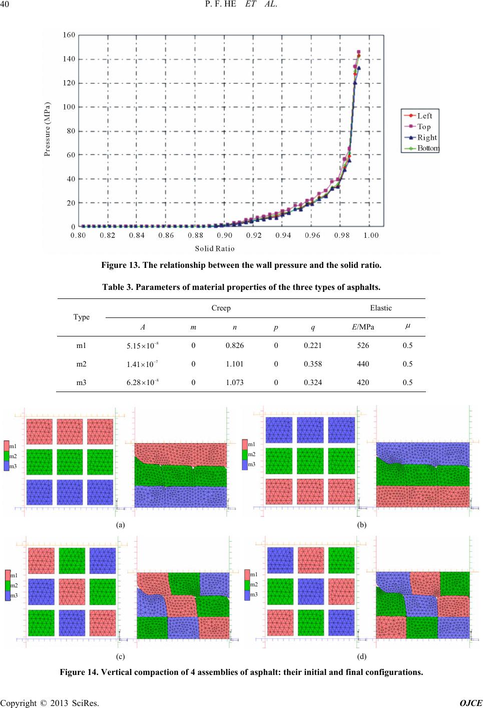 P. F. HE ET AL. 40 Figure 13. The relationship between the wall pressure and the solid ratio. Table 3. Parameters of material properties of the three types of asphalts. Creep Elastic Type A m n p q E/MPa m1 8 5.15 10 0 0.826 0 0.221 526 0.5 m2 7 1.41 10 8 6.28 10 0 1.101 0 0.358 440 0.5 m3 0 1.073 0 0.324 420 0.5 m1 m2 m3 m1 m2 m3 (a) (b) m1 m2 m3 m1 m2 m3 (c) (d) Figure 14. Vertical compaction of 4 assemblies of asphalt: their initial and final configurations. Copyright © 2013 SciRes. OJCE 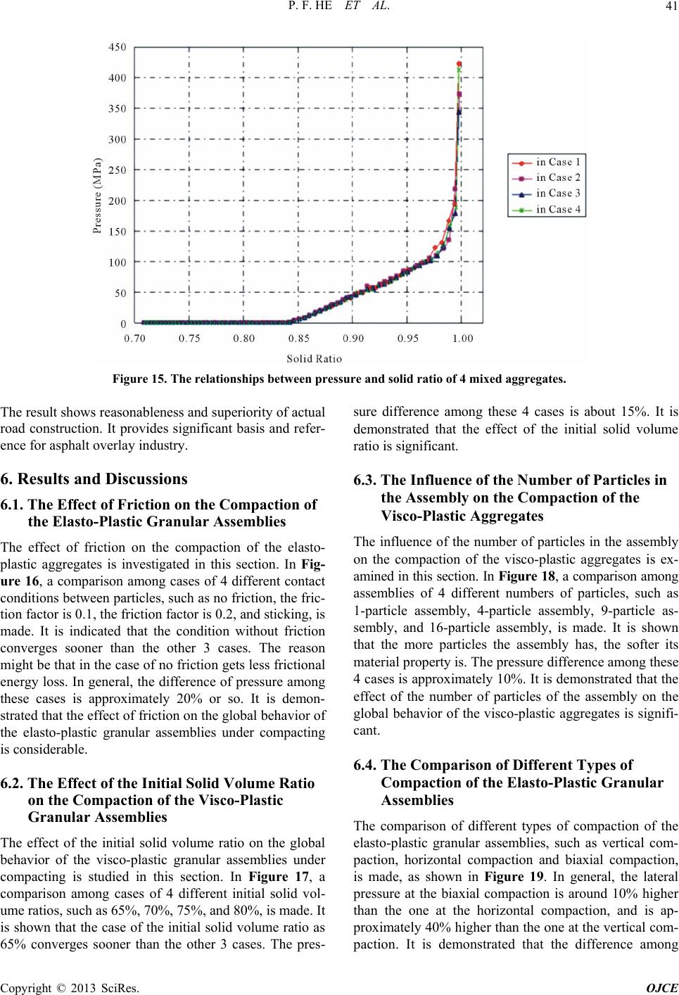 P. F. HE ET AL. 41 Figure 15. The relationships between pressure and solid ratio of 4 mixed aggregates. The result shows reasonableness and superiority of actual road construction. It provides significant basis and refer- ence for asphalt overlay industry. 6. Results and Discussions 6.1. The Effect of Friction on the Compaction of the Elasto-Plastic Granular Assemblies The effect of friction on the compaction of the elasto- plastic aggregates is investigated in this section. In Fig- ure 16, a comparison among cases of 4 different contact conditions between particles, such as no friction, the fric- tion factor is 0.1, the friction factor is 0.2, and sticking, is made. It is indicated that the condition without friction converges sooner than the other 3 cases. The reason might be that in the case of no friction gets less frictional energy loss. In general, the difference of pressure among these cases is approximately 20% or so. It is demon- strated that the effect of friction on the global behavior of the elasto-plastic granular assemblies under compacting is considerable. 6.2. The Effect of the Initial Solid Volume Ratio on the Compaction of the Visco-Plastic Granular Assemblies The effect of the initial solid volume ratio on the global behavior of the visco-plastic granular assemblies under compacting is studied in this section. In Figure 17, a comparison among cases of 4 different initial solid vol- ume ratios, such as 65%, 70%, 75%, and 80%, is made. It is shown that the case of the initial solid volume ratio as 65% converges sooner than the other 3 cases. The pres- sure difference among these 4 cases is about 15%. It is demonstrated that the effect of the initial solid volume ratio is significant. 6.3. The Influence of the Number of Particles in the Assembly on the Compaction of the Visco-Plastic Aggregates The influence of the number of particles in the assembly on the compaction of the visco-plastic aggregates is ex- amined in this sect ion. In Figure 18, a comparison among assemblies of 4 different numbers of particles, such as 1-particle assembly, 4-particle assembly, 9-particle as- sembly, and 16-particle assembly, is made. It is shown that the more particles the assembly has, the softer its material property is. The pressure difference among these 4 cases is approximately 10%. It is demonstrated that the effect of the number of particles of the assembly on the global behavior of the visco-plastic aggregates is signifi- cant. 6.4. The Comparison of Different Types of Compaction of the Elasto-Plastic Granular Assemblies The comparison of different types of compaction of the elasto-plastic granular assemblies, such as vertical com- paction, horizontal compaction and biaxial compaction, is made, as shown in Figure 19. In general, the lateral pressure at the biaxial compaction is around 10% higher than the one at the horizontal compaction, and is ap- proximately 40% higher than the one at the vertical com- action. It is demonstrated that the difference among p Copyright © 2013 SciRes. OJCE 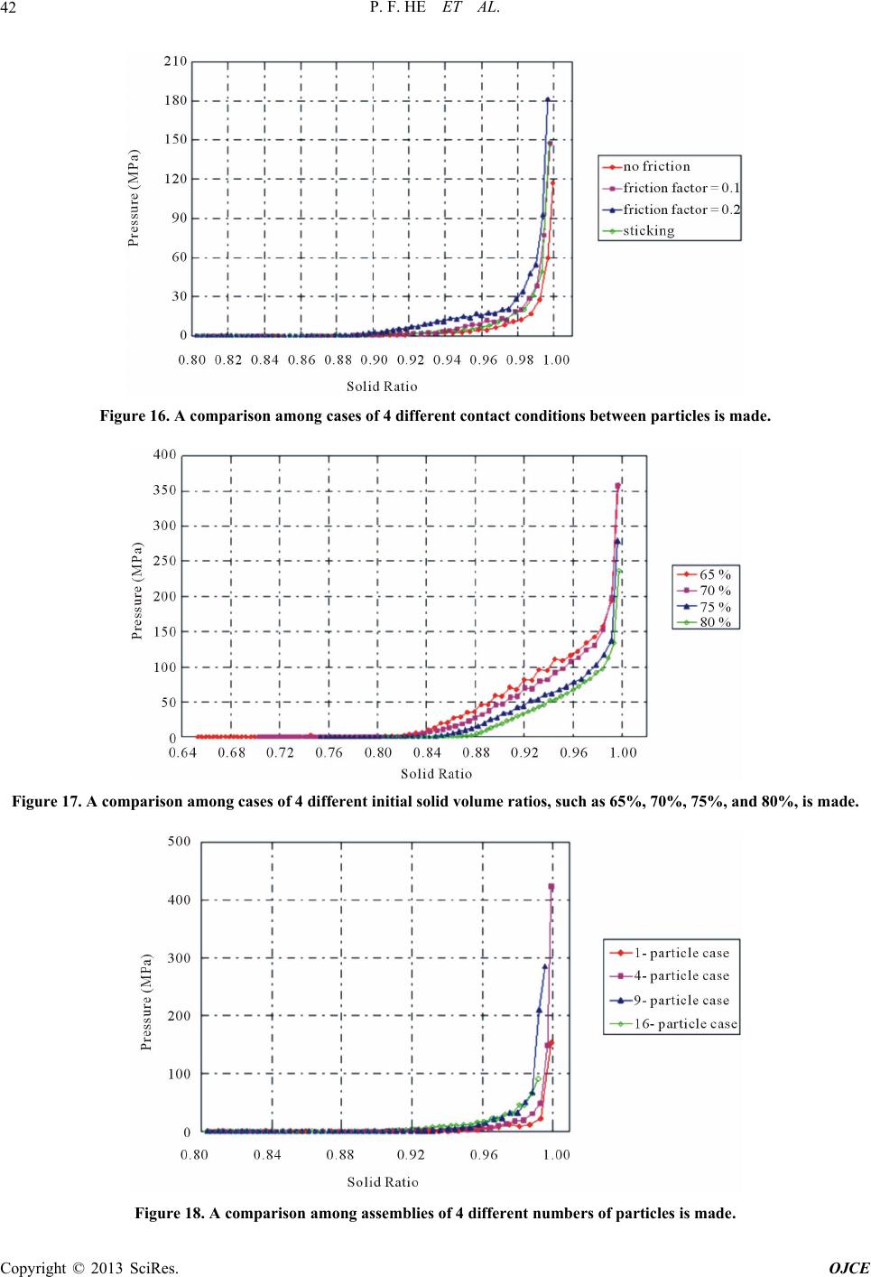 P. F. HE ET AL. 42 Figure 16. A comparison among cases of 4 different contact conditions between particles is made. Figure 17. A comparison among cases of 4 different initial solid volume ratios, such as 65%, 70%, 75%, and 80%, is made. Figure 18. A comparison among assemblies of 4 different numbers of particles is made. Copyright © 2013 SciRes. OJCE  P. F. HE ET AL. 43 Figure 19. A comparison of different types of compaction, such as vertical compaction, horizontal compaction and biaxial compaction, is made. different types of compaction is considerable. 6.5. Error Estimation Error estimation is made for all simulations of compac- tions of the granular materials in this section. It is as- sumed that materials of the granular assemblies are in- compressible. So one of the methods to estimate error of analytical results is calculating the ratio of the change of solid volume to the initial solid volume. In general, the average of errors in this study is about 0.6%. It is dem- onstrated that the results of the numerical analyses are acceptable and satisfactory. 7. Conclusions and Prospect In this paper, the compactions of elasto-plastic and visco- plastic polygonal granular materials are simulated using the finite element method. A couple of numerical experi- ments are made using the numerical model. Some new discoveries are presented as follows. First of all, in the simulation for the compaction of aggregates consising of particles of a single elasto-plastic incompressible mate- rial, it is demonstrated that if the initial solid volume ratios of the assemblies are the same, the more particles there are, the more oscillated the pressure-density curve is. But the general trend of the curve almost keeps the same. When the solid volume ratio is close to 1, stress in the biaxial compaction is around 15% lower than one in the uni-axial compaction. The effect of initial solid vol- ume ratio as well as the effect of friction among particles on the stress-density relation is considerable. In addition, in the simulation for the compaction of aggregates con- sisting of particles of a single viscous incompressible material, if the initial volumes of the assemblies are the same, when the solid volume ratio is close to 1, stress in the biaxial compaction is around 40% lower than one in the uni-axial compaction . Finally, the numerical model is extended to simulate the compaction of aggregates con- sisting of mixed particles of different viscous incom- pressible materials. It is indicated that, with minor modi- fication, the method could be used in a variety of pro- blems that can be represented using granular media, such as asphalt, polymers, aluminum, snow, food product, etc. However, the number of particles in the granular as- semblies presented in this paper is less than 25. To ex- tend the proposed numerical model to analyze the be- havior of large-scale granular systems, more studies on multi-scale methods, statistical random sampling models and stochastic simulations are necessary. 8. Acknowledgements This work is spo nso red b y National Natu ral S cien c e Foun- dation of China under grant 10972162. This support is gratefully acknowledged. REFERENCES [1] H. M. Jaeger and S. R. Nagel, “The Physics of Granular Materials,” Physics Today, Vol. 49, No. 4, 1996, pp. 32- 38. doi:10.1063/1.881494 [2] S. Luding, “Stress Distribution in Static Two Dimen- sional Granular Model Media in the Absence of Friction,” Physical Review E, Vol. 4, No. 55, 1997, pp. 4720-4729. doi:10.1103/PhysRevE.55.4720 [3] Y. M. Bashir and J. D. Goddard, “A Novel Simulation Method for the Quasi-Static Mechanics of Granular As- semblages,” Journal of Rheology, Vol. 5, No. 35, 1991, pp. 849-885. doi:10.1122/1.550160 [4] M. A. Tzaferopoulos, “On the Numerical Modeli ng of Con- vex Particle Assemblies with Friction,” Computer Me- thods in Applied Mechanics and Engineering, Vol. 127, Copyright © 2013 SciRes. OJCE  P. F. HE ET AL. 44 No. 1-4, 1995, pp. 371-386. doi:10.1016/0045-7825(95)00852-8 [5] S. N. Coppersmith, C. H. Liu and O. Narayan, “Model for Force Fluctuations in Bead Packs,” Physical Review E, Vol. 5, No. 53, 1996, pp. 4673-4685. doi:10.1103/PhysRevE.53.4673 [6] H. G. Matuttis, “Simulations of the Pressure Distribution under a Two Dimensional Heap of Polygonal Particles,” Granular Matter, Vol. 2, No. 1, 1998, pp. 83-91. doi:10.1007/s100350050013 [7] M. Satake, “Tensorial form Definitions of Discrete-Me- chanical Quantities for Granular Assemblies,” Interna- tional Journal of Solids and Structures, Vol. 41, No. 21, 2004, pp. 5775-5791. doi:10.1016/j.ijsolstr.2004.05.046 [8] F. Emeriault and C. Claguin, “Statistical Homogenization for Assemblies of Elliptical Grains: Effect of the Aspect Ratio and Particle Orientation,” International Journal of Solids and Structures, Vol. 41, No. 2, 2004, pp. 5837- 5849. doi:10.1016/j.ijsolstr.2004.05.047 [9] S. J. Antony and R. Kuhn, “Influence of Particle Shape on Granular Contact Signatures and Shear Strength: New Insights from Simulations,” International Journal of Sol- ids and Structures, Vol. 41, No. 21, 2004, pp. 5863-5870. doi:10.1016/j.ijsolstr.2004.05.067 [10] Y. C. Wu, E. G. Thompson, P. R. Heyliger and Z. H. Yao, “The Compaction of Blended Aggregates of Non-Spheri- cal Linear Viscous Particles,” Computer Methods in Ap- plied Mechanics and Engineering, Vol. 193, No. 36-38, 2004, pp. 3871-3890. doi:10.1016/j.cma.2004.02.008 [11] Y. C. Wu, “Automatic Adaptive Mesh Upgrade Schemes of the Step-by-Step Incremental Simulation for Quasi Linear Viscoplastic Granular Materials,” Computer Meth- ods in Applied Mechanics and Engineering, Vol. 197, 2008, pp. 1479-1494. doi:10.1016/j.cma.2007.11.020 [12] Y. Wu, J. Xiao and C. Zhu, “The Compaction of Time- Dependent Viscous Granular Materials Considering Iner- tial Forces,” Acta Mechanica Solida Sinica, Vol. 24, No. 6, 2011, pp. 495-505. Copyright © 2013 SciRes. OJCE
|