 Wireless Sensor Network, 2010, 2, 755-767 doi:10.4236/wsn.2010.210091 Published Online October 2010 (http://www.SciRP.org/journal/wsn/). Copyright © 2010 SciRes. WSN Priority-Based Hybrid MAC for Energy Efficiency in Wireless Sensor Networks Ines Slama, Badii Jouaber, Djamal Zeghlache Telecom and Management SudParis, Evry, France E-mail: {Ines.slama, Badii.Jouaber, Djamal.Zeghlache}@it-sudparis.eu Received June 30, 2010; revised August 9, 2010; accepted September 15, 2010 Abstract This paper introduces I-MAC, a new medium access control protocol for wireless sensor networks. I-MAC targets at improving both channel utilization and energy efficiency while taking into account traffic load for each sensor node according to its role in the network. I-MAC reaches its objectives through prioritized and adaptive access to the channel. I-MAC performances obtained through simulations for different network to- pologies, scenarios and traffic loads show significant improvements in energy efficiency, channel utilization, loss ratio and delay compared to existing protocols. Keywords: MAC Protocol, Prioritization, Energy Efficiency, Throughput, Channel Utilization, Wireless Sensor Networks 1. Introduction A critical design issue for wireless sensor networks (WSNs) is the development of novel communication protocols and algorithms that efficiently tackle the resource con- straints and application requirements [1,2]. Therefore, power aware and power efficient protocols at each layer of the communication are required [2]. In WSNs, the MAC layer is considered as the main responsible of energy consumption. Indeed, it has been identified that the main reasons of energy waste in WSNs are: collisions, overhearing, protocol overhead and fi- nally transmission and reception operations [3]. At the medium access layer, both CSMA and TDMA techniques have been widely used. CSMA is a contention based access protocol consid- ered as simple, flexible and robust. It is a distributed mechanism that does not require clock synchronization or any knowledge of the network topology. Moreover, nodes can dynamically join or leave the network without additional overhead or operations. However, all this comes at the cost of collisions that occur when two or more nodes (within the same radio range) transmit at the same time. Collisions can cause serious energy waste, high overhead and throughput degradation. CSMA per- formance decreases under high contention in terms of both energy consumption and channel utilization. On the contrary, in TDMA, collisions are reduced by scheduling the transmissions of neighboring nodes and minimizing simultaneous transmissions [4]. Thus, TDMA can deliver very good performance especially under high contention. Moreover, it can provide higher energy saving than CSMA since it allows avoiding wasted energy due to collisions, idle listening and overhearing. However, the challenge with TDMA is to setup an efficient and scalable schedule that ensures collision free transmission times for all nodes in the network. Additionally, since sensor networks may undergo frequent topology changes caused by battery outage and node failures, the TDMA schedule should be able to gracefully handle these varia- tions and dynamically adapt (frame length and/or time slot assignment) with respect to energy conservation aims. Moreover, TDMA gives much lower channel utili- zation than CSMA under low contention as nodes can only transmit during their scheduled slot. Finally, TDMA requires clock synchronization, which incurs high-energy overhead. These difficulties with TDMA and CSMA suggest that a stand-alone TDMA or CSMA scheme cannot be effi- cient. On the other hand, in most of WSNs topologies, some nodes are heavily responsible of forwarding operations because of their central position or because they are closer to the base station (sink) and therefore, most of the routes go through them. Obviously, these critical nodes require more bandwidth resources to achieve their for-  I. SLAMA ET AL. Copyright © 2010 SciRes. WSN 756 warding tasks. Besides, since these nodes have to trans- mit much more packets than other nodes (relaying role), they usually spend more energy and die earlier, which can affect the entire network lifetime. Controlling access to the channel in wireless sensor networks plays then a key role in determining channel utilization, energy consumption and fairness in channel usage [4]. Optimizing channel and energy utilization have been the main focus of significant researches over the last years [4-11]. Different approaches dealing with this topic have been proposed. In [4,6,7], it has been shown that hybrid MAC schemes outperform contention based and schedule based schemes. Indeed, hybrid approaches com- bine the flexibility of contention-based schemes and the efficiency of schedule based schemes. Unfortunately, most of these hybrid mechanisms equally consider nodes and do not consider the heterogeneity in their loads and roles in the networks, which greatly motivated our work. 2. Prior Work Prior research efforts in designing MAC protocols for wireless sensor networks have resulted in a number of interesting solutions. Some of the proposed schemes are mainly designed to improve the channel utilization. Some others focus on energy efficiency, which remains the most important challenge in WSNs. The most popu- lar and relevant to our work are the followings: S-MAC (Sensor-MAC) protocol [10] uses the Carrier Sense Multiple Access with Collision Detection (CSMA/ CD) algorithm. It is composed of two phases: a listen period and a sleep period. During the sleep period the nodes can switch off their transceiver. After the sleep period, the nodes wake up and listen whether there is a communication addressed to them or if they can address themselves a communication to their neighbours. This periodic sleep/listen schedule is set up within a virtual cluster formed by neighbouring nodes. The listen and sleep periods should be then locally synchronized be- tween nodes. The listen period is divided into two sec- tions. The first section is reserved for SYNC messages used for synchronization and containing an identification number of the sender and the next time slot where nodes should go to sleep. The second section is reserved for request to send RTS messages. The design goal of S-MAC is essentially energy effi- ciency. The energy waste caused by idle listening is re- duced by sleep schedules. Moreover, time synchroniza- tion overhead may be prevented by sleep schedule an- nouncements. However, since S-MAC employs RTS/CTS, the overhead is quiet high because most data packets in sensor networks are usually small. Moreover, when send- ing broadcast messages, RTS/CTS is not used which will increase the probability of collisions. Finally, the lis- ten/sleep period size is predefined and fix which limits the efficiency of the protocol under variable traffic. T-MAC (Time-out MAC) [11] is very similar to S- MAC. It is proposed to improve the energy efficiency and throughput performances of S-MAC by introducing an “adaptive” duty-cycle that dynamically adjusts the length of the active periods according to the load varia- tions. A node can save energy by switching off its radio when not concerned with any communication and then avoid overhearing and idle listening energy waste. B-MAC (Berkley-MAC) [12] is a carrier sense media access protocol for wireless sensor networks that pro- vides a flexible interface to ensure ultra low power op- eration, high channel utilization and collision avoidance. To improve the channel utilization, B-MAC uses the clear channel sensing technique (CCA). Moreover, B- MAC supports Low Power Listening (LPL), which aims to surmount the idle listening problem by requiring po- tential receivers to wake up periodically and briefly to listen for activity on the channel. The implementation of LPL is integrated with the hardware, and is not currently available for most platforms. B-MAC is shown to have better performances than S-MAC and T-MAC in terms of energy efficiency and throughput. Z-MAC (Zebra-MAC) [4] is a hybrid MAC protocol designed for wireless sensor networks and combines the strengths of CSMA and TDMA while offsetting their weaknesses. It operates in two modes: the set-up mode and the transmission mode. During the setup mode, each node is assigned a time slot. For a given slot, we denote by “owner”, the node to which that slot is allocated. All other nodes are denoted by “non-owners”. Z-MAC uses DRAND [13] to assign slots to nodes. DRAND is run during setup phase and guarantees that no two nodes within a two-hop neighbouring be assigned the same time slot. In the transmission mode, time is divided into slots. Z-MAC uses CSMA as the baseline MAC scheme and uses a TDMA schedule to enhance contention reso- lution. In Z-MAC, a node may transmit during any time slot. Before a node transmits, it senses the channel and only transmits a packet if it is sensed clear. However, the owner of the slot always has higher priority than other nodes in accessing the channel. Hence, by combining CSMA and TDMA approaches, Z-MAC delivers a ro- bust scheme, which, in worst case, performs as well as CSMA. TH-MAC [9] is a traffic pattern aware hybrid MAC protocol inspired from Z-MAC. It uses A-DRAND as slot assignment algorithm. A-DRAND is an improved version of DRAND for clustered wireless sensor net- works where cluster heads require more slots to relay packets. To allot more slots to cluster heads and coordi- nators, the time frame is divided into two parts: a re-  I. SLAMA ET AL.757 served part and a non-reserved part. If a node is a normal sensor, it can only select a slot from the non-reserved part and not yet selected by none of its one-hop or two-hop neighbours. However, if the node is a cluster head or a coordinator, it can get a slot, not only from the non-reserved part but also from the reserved part. TH- MAC can assign then more slots to cluster heads and backbone nodes to improve channel utilization and th- roughput. BAZ-MAC (Bandwidth Aware Z-MAC) [8] is another hybrid MAC protocol inspired from Z-MAC and pro- posed for Ad Hoc networks. Like TH-MAC, BAZ-MAC uses a bandwidth aware slot allocation algorithm during the set-up phase, to assign slots to the nodes according to their bandwidth requirements. S-MAC and T-MAC mainly consider the energy effi- ciency problem in WSNs, whereas TH-MAC and BAZ- MAC address resource allocation according to nodes’ bandwidth needs. Moreover, bandwidth resource alloca- tion in these two latter mechanisms is rather static since it is performed during the setup phase. If changes in bandwidth requirements occur during the transmission phase, the allocation does not auto-adapt. The unique solution is to re-run at least a part of the initial slot allo- cation algorithm. In the following, we propose a dynamic mechanism able to automatically adapt to bandwidth requirement changes at each node while maintaining energy saving objectives and improving resource utilization. 3. I-MAC Protocol Design I-MAC is a new hybrid MAC protocol designed for wire- less sensor networks. It not only combines the strengths of CSMA and TDMA techniques while obviating their weaknesses but also introduces an adaptive priority scheme for channel access. I-MAC operates in two phases: a set-up phase and a transmission phase. During the set-up phase, several op- erations are successively run: Neighbours discovery TDMA Slot assignment Local framing Global synchronization These operations run only once during the setup phase and do not run until a significant change in the network topology (such as sensor’s position changes, joining or leaving node) occurs. Neighbours discovery operation is run by each node and mainly consists in determining the list of its one-hop and two-hop neighbours. This list is then used as an input for the slot assignment operation. The slot assignment problem can be defined as allo- cating a time slot for each node such that two nodes within two-hop distance should not be allocated the same time slot. To this end, DNIB (Distributed Neighborhood Information Based algorithm), an energy efficient and scalable TDMA channel scheduling algorithm is pro- posed. DNIB achieves distributed and parallel TDMA scheduling based on 2-hop neighborhood information, which allows handling the dynamic topology changes with low complexity and small energy waste. After the slot assignment phase, each node reuses its assigned slot periodically in every predetermined period called Local Frame. As in Z-MAC [4], we denote a node assigned a given time slot the owner of that slot and the other nodes the non-owners of that slot. Once each node computes its Local Frame, Global Synchronization is set-up and the Transmission phase can then be started. During the transmission phase, time is divided into slots. All nodes are allowed to transmit during any slot. Before transmitting, a node performs carrier sensing and transmits a packet when the channel is clear. The channel access by the different nodes is controlled by a priority scheme. Indeed, the idea behind I-MAC is to assign dif- ferent levels of priority to nodes according to their roles. For each node, the priority is implemented by adjusting the initial contention window size according to its prior- ity level. If it has something to transmit, the owner of the slot is guaranteed to get the access first. Whenever the owner has no data to transmit, or when the slot is not owned, non-owners can compete to use the slot. The chance a non-owner node gets a slot depends on its pri- ority level. Assigning a higher priority to forwarding nodes (that have more packets to transmit) ensures that these nodes will be able to transmit ahead of low priority nodes (in most of the cases) and hence improve the channel utili- zation. At the same time, and since shorter back off pe- riods are given to higher priority nodes, their energy consumption is reduced [14]. In addition, since competi- tion to access the channel (to get a slot) occurs between nodes within the same priority group, probability of col- lisions is lowered because the number of competing nodes within each group is lower than the total number of nodes [14]. This energy saving meets the main re- quirement of WSNs that is lifetime maximization, since it is known that highly loaded nodes usually run out of energy first. In I-MAC, priorities are dynamically attributed during the transmission phase according to the dynamic topol- ogy changes and hence to the requirements of the nodes in terms of bandwidth and energy. Resource allocation is statically performed by DNIB during the set up phase and do not consider each node requirements. However, the priority scheme, used in the transmission phase, comes Copyright © 2010 SciRes. WSN  I. SLAMA ET AL. Copyright © 2010 SciRes. WSN 758 to dynamically and fairly distribute the resources over nodes according to their requirements. In the following, we first describe how we implement the different set-up phase operations mentioned above and then discuss how they are integrated with transmis- sion control in I-MAC. 3.1. Set-up Phase of I-MAC 3.1.1. TDMA Slot Assignment Algorithm: DNIB TDMA scheduling can be generally defined as assigning transmitting and receiving slots to each node so that col- lision free transmissions can be achieved [15]. Transmissions may collide in two ways typically re- ferred to as primary conflict and secondary conflict [16]. Primary conflict occurs when a node must do more than one thing at the same time, for instance, transmitting and receiving at the same time or receiving from two nodes at the same time. This latter problem is also referred to as hidden terminal problem. Secondary conflict occurs when a receiver u, tuned to a particular transmitter v, is within the transmission range of another transmitter whose trans- mission, though not intended to u, interferes with the transmission of v. Combining these two definitions, we can say that two nodes are in conflict if and only if the simultaneous trans- missions from these two nodes cause radio interference at some node. There are two kinds of TDMA scheduling: Broadcast and link [16]. In the broadcast scheduling, the entities scheduled are the nodes whereas, in the link scheduling, they are the links between the nodes. Hence, in the broad- cast scheduling, conflict can happen among all the nodes within a two-hop neighbourhood. In the link scheduling, conflict can happen among all the nodes within a onehop neighbourhood of a transmitter and a receiver. In this work, we focus on broadcast scheduling. From above definitions, we can define the slot assign- ment problem as finding a time slot for each node, such that no two nodes within two-hop distance should be allo- cated the same transmitting slot. An appropriate slot assignment algorithm should allo- cate as few slots as possible to ensure more spatial reuse and shorter delay. It should also be as simple as possible with low running time (the maximum time taken for all the nodes in the network to be assigned a slot for all executions of the algorithm) and message complexity (the number of messages exchanged between all the nodes in the network to decide on the time slots). Other- wise, high-energy waste can be expected due to mes- sages transmission and reception operations and over- head. In I-MAC, we use DNIB (Distributed Neighborhood Information Based algorithm) a new time slot assignment algorithm that we proposed in a previous work. The idea behind the DNIB algorithm is to let each node decide its own slot according to the information collected from its one and two-hop neighbors. This in- formation includes neighbors IDs and whether they are or not yet scheduled. The DNIB algorithm, running in parallel at each node, is composed of the following procedures: Slot assignment procedure: During the slot assignment procedure, each non-sche- duled node selects the minimum unassigned slot within its one and two-hop neighbors. Update procedure: Once a node gets assigned a slot, it sends a “one-hop broadcast” message to inform its one-hop neighbors. Those one-hop neighbors send in their turn a “two-hop broad- cast” message to update two-hop neighbors. The “one-hop broadcast” message contains: - the scheduled node id, - the assigned slot id and - a “two-hop broadcast schedule” that defines for each one-hop neighbor the slot in which it will transmit the two-hop broadcast message. The “two-hop broadcast” message contains all already known scheduling information about one-hop neighbors. During this procedure, two types of collisions may occur: - collisions between “two-hop broadcast” mes- sages. - collisions between “two-hop broadcast” mes- sages and “one-hop broadcast” messages. The “two-hop broadcast schedule” defined above (sent within the “one-hop broadcast” message) is used to avoid the first type of collisions. Collisions of the second type can be reduced by de- laying one-hop broadcast messages. In DNIB, we pro- pose that, before sending the “one-hop broadcast” mes- sage, each scheduled node should wait a predetermined number of slots. Recovery procedure: This procedure is activated when a node does not suc- ceed to get scheduled for a predetermined period of time. This may happen for instance because it misses informa- tion about some of its one and/or two-hop neighbors. In this case, the node can send a “request” message to its one-hop neighbors. This request message triggers an up- date procedure forcing its one-hop neighbors to send a “two-hop broadcast” message with all already known scheduling information. The performances of DNIB were evaluated and results have shown very good performances in terms of running time, message complexity and energy efficiency com-  I. SLAMA ET AL.759 pared to existing slot assignment algorithms. An example of slot assignment allocation using DNIB is illustrated in Figure 1. Readers interested in more details, analysis and simu- lation results of DNIB are referred to [17]. 3.1.2. Local Framing Once slot allocation is achieved, the next issue concerns the TDMA frame size of each node. Indeed, after being assigned a slot, a node needs to know in how many slots it will be able to reuse this slot to transmit data in a colli- sion free manner. We call this period time frame and we use the Time Frame rule (TF rule) proposed in Z-MAC [4] to determine its size. According to this rule, each node maintains its proper local time frame that depends on its two-hop neighbourhood size and that avoids any collision with its neighbours. Local frame approach makes the slot assignment scheme adaptive to dynamic topology changes and improves the channel utilization in non uniform density networks. Readers interested in these issues are referred to [4] for more details. The TF rule is defined as follows: Let ASNmax be the maximum allocated slot number within two-hop neighbourhood of a node. The local frame size of this node is equal to 2a, such that: a-1 a max 2 ASN 2 Thus, a node can reuse its assigned slot each 2a slot with the guarantee that no other node within its two-hop neighbourhood uses any slot that it uses [4]. 3.1.3. Global Synchronization Once each node computes its Local Time Frame, a glo- bal synchronization should be set-up i.e., each node starts Figure 1. A DNIB slot assignment example. The top figure shows the network topology and the numbers are the id of the nodes. The bottom figure shows the slot schedule of all nodes. its time slot 0 at the same time. Like in Z-MAC, this is achieved by setting the beginning of the real time (when the synchronized clock value is 0) to be the beginning of time slot 0. The global synchronization is performed only once and during the set-up phase. However, each node needs to run a local synchronization scheme during the transmis- sion phase. At the end of the setup phase, each node forwards its local frame size and its assigned slot number to its two- hop neighbourhood. Thus, before starting the transmis- sion phase, a node knows at which slots each of its one- hop and two-hop neighbours will transmit. After this phase, all nodes are synchronized to slot 0 and ready to transmit. During the transmission phase, a local synchronization will be run at each node. 3.2. Transmission Control of I-MAC In I-MAC, we propose to use three levels of priority. The priority of each node is set according to its role within the network and to its traffic load. Three priority groups are then formed. We discuss in a future section how pri- orities can dynamically adapt to network changes. Let’s denote by gk (k = 0, 1, 2) the group with priority level k. After the slot allocation phase, each node can reuse its assigned slot periodically after a predetermined number of slots (the node’s local frame). We remind that during the transmission phase, all nodes can compete to get the slot. The owner of the slot is al- ways given earlier chance to access the channel. If the slot is not used because not owned or because its owner has no data to transmit, non-owners can compete to use this slot. The chance a non-owner node gets a slot de- pends on its priority level as well as its priority group size. The competition is achieved by using a parameterized carrier sensing before transmitting data. Nodes can only transmit if the channel is sensed clear. Priority is imple- mented by adjusting the initial contention window size according to the owner/not-owner status and to the prior- ity group of each node. Owners are always guaranteed to get the access first. Within non-owners, those belonging to a higher priority group are able (in most of the cases) to transmit ahead of those belonging to lower priority ones. As a consequence, owners always transmit in a collision free manner since they have early access to their allocated slots. For non-owners, collisions are re- duced since competitions mostly occur within reduced number of nodes (i.e. same priority group). This has the effect of significantly increasing resource usage ratio and decreasing energy consumption. Energy saving is also achieved at high priority nodes while trying to access the channel since they are given shorter back off periods. Copyright © 2010 SciRes. WSN  I. SLAMA ET AL. Copyright © 2010 SciRes. WSN 760 Finally, I-MAC allows loaded nodes to which are attrib- uted a high priority to get more frequently access to the channel (during non-owned/free slots) in order to deliver data and then improve the channel utilization and in- crease the throughput. 3.2.1. Priority Scheme The priority scheme that we propose in I-MAC is in- spired from IEEE802.11e. In I-MAC, like in IEEE802.11e, if a node that has data to transmit listens to the medium and find it idle for a time interval greater than an Arbitration Interframe Space (AIFS) then it contends to access to the medium. A back- off time counter is then randomly selected between 0 and Contention Window (CW). At the first transmitting at- tempt, CW is assigned the value CWmin and will increase up to the maximum value CWmax = 2mCWmin due to suc- cessive collisions. Once the backoff timer expires and if the channel is idle, the node can begin transmitting the data. The AIFS values as well as the CW limits depend on the priority level. Smaller values of AIFS and CW yield higher priority. Therefore, a node with a small AIFS has a higher priority than a node with a greater one. More- over, assigning a short CW to a high priority node en- sures that in most cases, this node is able to transmit ahead of low priority nodes. The values of CW limits and AIFS used in I-MAC for different priority levels are given in Table 1. For owners, CWmin = CWmax = CWo. This is because collisions be- tween owners almost never happen since their slots are scheduled a priori by the slot allocation algorithm to avoid collision. For non-owners belonging to any priority group, AIFS = CWo. This is to ensure that owners, if they have something to transmit, be guaranteed to access the channel (get the slot). Figure 2 gives an illustration of how the priority is implemented in I-MAC. 3. 2. 2. Transmission Rule When a node i has data to transmit, it checks whether it is the owner of the current slot. If it is the case, then it Table 1. Priority parameters. Non owner Node category Group0 Group1 Group2 Owner Priority level 0 1 2 3 AIFS CWo CWo CWo 0 CWmin CWno,min (CWno,min + 1)/2-1 (CWno,min + 1)/4-1CWo CWmax CWno,max CWno,min (CWno,min + 1)/2-1CWo Figure 2. Priority based channel access in I-MAC. selects a random back off within [0, CWo]. When the back off timer expires, it runs CCA (clear channel as- sessment) to check whether the channel is clear. If it is the case, the node transmits its data. However, if the channel is busy, the node waits until it becomes clear to repeat the process. If the node i is a non-owner of the current slot, then it waits for CWo (AIFS) and then takes a random back off within [CWo, CWnok], k = 0, 1, 2, the contention window corresponding to the priority group gk it belongs to. When the back off timer expires, the non-owner runs CCA and if the channel is clear, it trans- mits. However, if the channel is busy, the node waits until it becomes clear and repeats the process. We can see from Table 1 that non-owners with higher priority have shorter contention window than those with lower priority. This lets them in most cases get the slot ahead those with low priority. 3.2.3. TDMA Slot Size The TDMA slot size is kept constant for a given scenario. It is calculated as the sum of CWo, CWno,max correspond- ing to the lowest priority, the CCA period, one packet propagation time and time taken to receive an acknowl- edgement if the transmission succeed. 3.2.4. Receiving Schedule of I-MAC In I-MAC, the transmission schedule is statically defined during the set-up phase by DNIB. However, since in I-MAC a node can transmit at any time, a reception sche- dule must be defined. An appropriate solution, as men- tioned in Z-MAC, is to rely on the LPL (Low Power Listening) mechanism proposed in [12] and which uses the preamble sampling method to reduce the energy consumed in idle listening. In LPL, each node remains asleep and periodically wakes up to check whether the channel is busy. When a node transmits data, a long preamble is attached to the packet. Once the receivers listen this preamble, they keep their radio on until they receive the real data. The preamble is generally longer than the listening interval also called check period. This mechanism was basically proposed to guarantee reliable  I. SLAMA ET AL.761 data transmission, as well as low power consumption. 3.2.5. Dynamic Priority Attribution As explained previously, attributing a high priority to a node gives it more chances to access the channel than other low priority nodes and allows it to save some en- ergy. The priority of each node is then set at the begin- ning of the network deployment according to the re- quirements of each node and the constraints it may face. However, this priority should not be statically set. Indeed, many changes may occur in the network. Some of the reasons behind these network changes are addition or lost of new nodes, permutation of node’s roles as in clustered networks where the cluster head responsibility is shared by the cluster members, moving nodes or vary- ing interference which may alter the connectivity of the network, change the routes from the sources to the base station and hence modify the traffic load of some nodes, etc. Therefore, the priority scheme must be able to dy- namically adapt to the network changes. An appropriate solution is to make nodes auto attribute their own priority level. This priority can then be set according to some statistics collected by these nodes during their lifetime and which may concern the forwarding load, the re- maining battery charge, the distance to the base station, etc. 4. Performance Evaluation This section is dedicated to the evaluation of the per- formances of the overall I-MAC protocol in terms of energy efficiency as well as channel utilization. 4.1. Simulations Setup The aim of these simulations is to assess I-MAC through- put and energy efficiency performances. Comparative simulations of I-MAC and Z-MAC are run on NS2 simulator. Z-MAC implementation over NS2 provided in [18] is used. Default parameter settings are summarized in Tables 2-4 T0 and Tno, (respectively the owner and non-owner contention windows of Z-MAC as defined in [4]), are equal to 8 and 32 slots respectively. The following one-hop and multi-hop scenarios (simi- lar to the ones used in [4] and [8]) have been investigated. 4.1.1. One Hop Scenario This scenario is inspired from [4] where n nodes and a base station are placed at one-hop distance from each other so that there are no hidden terminals (see Figure 3). Each node belongs to a priority group, which corresponds Table 2. Energy parameters. Power Value(J) etx 1 erx 0.67 eidle 0.82 erx = 0.5494 Table 3. Default settings of various parameters for I-MAC and Z-MAC. Parameters Default values Communication bandwidth 19.2 kbps Communication range 40 m Contention slot size 400 µs Transmission slot size 60 ms Table 4. Priority parameters of I-MAC. Non owner Node cate- gory Group0Group1 Group2 Owner Priority level0 1 2 3 AIFS (slot)8 8 8 0 CWmin (slot)32 16 8 8 CWmax (slot)64 32 16 8 Figure 3. One-hop scenario topology. to a priority level equal to 2, 1 or 0. All the nodes trans- mit data to the base station, they always have something to transmit and they transmit with the full transmission power. This scenario is used to: First evaluate the achievable throughput or channel utilization of I-MAC for different levels of contention within a one-hop neighbourhood and compare it to Z- MAC. Second, to show the influence of the prioritization scheme between the three different groups of nodes (dif- ferent priority groups) on the channel utilization as well as the energy consumption per transmitted packets. Copyright © 2010 SciRes. WSN  I. SLAMA ET AL. Copyright © 2010 SciRes. WSN 762 4.1.2. Multi-Hop Scenario In this scenario, the number of nodes is set to 10 and the number of senders varies from 1 to 10. The different priority levels are alternatively distributed over the send- ing nodes. The senders send data to the base station and are considered as having always something to transmit. According to the local frame rule, the frame size of I- MAC and Z-MAC is 16 slots (0.96 s). For the multi-hop scenario, we adopted the topology used in [8] to demonstrate the effectiveness of the proposed approach. The topology consists in two clusters separated by a three-hop distance (see Figure 4). Each cluster is composed of 8 transmitting nodes. The second cluster also contains a base station to which all the transmissions are destined. The nodes in the cluster 1 deliver the data to the base station through node 1 and node 0. These two nodes have an important role in the network since they relay the traffic coming from all nodes in cluster 1. Such nodes can then experience bottleneck in case of high traffic and consume a lot of energy for forwarding pur- poses. To evaluate the efficiency of our scheme, each node is attributed a priority. All the nodes in the clusters have a priority level equal to 0. Nodes 1 and 0 have a higher priority equal to 1. When n users are said to be senders, the n highest id nodes (not including the base station) are transmitting. Moreover, in the original version of Z-MAC provided in [18], a node can only transmit one packet per slot. The slot size is equal to the sum of the maximum contention back off duration and the necessary time to transmit a packet and receive the acknowledgment. When the con- tention back off is smaller than this maximum, the re- maining time is wasted. We decided as in [8] to allow the nodes to transmit more than one packet at a time when- ever it is possible. It has been proved in [8] that this sig- nificantly improves Z-MAC throughput. Figure 5 depicts the channel utilization of the three different priority groups independently. It shows that the channel utilization obviously depends on the priority level of the senders. The higher the priority is the more important is the corresponding channel utilization. In fact and to be fairer, let’s consider the 3, 6 and 9 senders points in Figure 5 where the number of nodes in each priority group is the same. We can see that in the three cases, the channel utilization value of priority 2 (0.31 for 6 senders point) is higher than the one of priority 1 (0.18) which is itself higher than the one of priority 0 (0.13). This happens because high priority nodes use smaller congestion back off window size than nodes with low priority. Therefore, during empty/non-owned slots, nodes who belong to a high priority group are in most cases able to transmit ahead of those belonging to low priority ones. 4.2. Simulations Results We present in the following the results and analysis of the simulations run for the scenarios described above. Both channel utilization and energy efficiency are inves- tigated. Figures illustrating the comparison between our proposed scheme and Z-MAC are then provided. 4.2.1. Channel Utilization The following sub-sections describe the observations con- cerning the channel utilization. Channel utilization is calculated here as the fraction of the channel capacity which was utilized to successfully transmit data. a) One-hop scenario Figure 4. Multi-hop scenario topology. 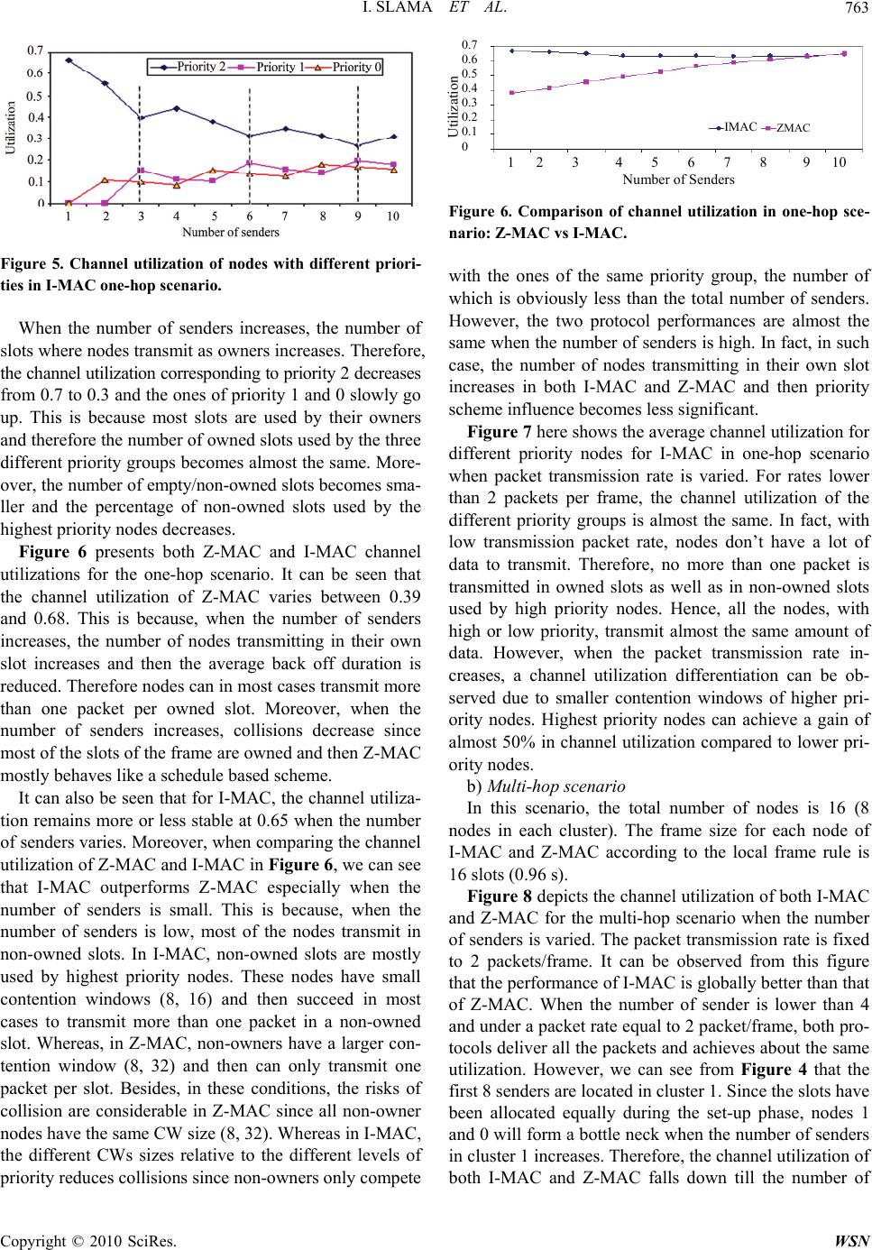 I. SLAMA ET AL. 763 Figure 5. Channel utilization of nodes with different priori- ties in I-MAC one-hop scenario. When the number of senders increases, the number of slots where nodes transmit as owners increases. Therefore, the channel utilization corresponding to priority 2 decreases from 0.7 to 0.3 and the ones of priority 1 and 0 slowly go up. This is because most slots are used by their owners and therefore the number of owned slots used by the three different priority groups becomes almost the same. More- over, the number of empty/non-owned slots becomes sma- ller and the percentage of non-owned slots used by the highest priority nodes decreases. Figure 6 presents both Z-MAC and I-MAC channel utilizations for the one-hop scenario. It can be seen that the channel utilization of Z-MAC varies between 0.39 and 0.68. This is because, when the number of senders increases, the number of nodes transmitting in their own slot increases and then the average back off duration is reduced. Therefore nodes can in most cases transmit more than one packet per owned slot. Moreover, when the number of senders increases, collisions decrease since most of the slots of the frame are owned and then Z-MAC mostly behaves like a schedule based scheme. It can also be seen that for I-MAC, the channel utiliza- tion remains more or less stable at 0.65 when the number of senders varies. Moreover, when comparing the channel utilization of Z-MAC and I-MAC in Figure 6, we can see that I-MAC outperforms Z-MAC especially when the number of senders is small. This is because, when the number of senders is low, most of the nodes transmit in non-owned slots. In I-MAC, non-owned slots are mostly used by highest priority nodes. These nodes have small contention windows (8, 16) and then succeed in most cases to transmit more than one packet in a non-owned slot. Whereas, in Z-MAC, non-owners have a larger con- tention window (8, 32) and then can only transmit one packet per slot. Besides, in these conditions, the risks of collision are considerable in Z-MAC since all non-owner nodes have the same CW size (8, 32). Whereas in I-MAC, the different CWs sizes relative to the different levels of priority reduces collisions since non-owners only compete 0.7 0.6 0.5 0.4 0.3 0.2 0.1 0 Utilization IMAC ZMAC 1 2 3 4 5 6 7 8 9 10 umber of Senders Figure 6. Comparison of channel utilization in one-hop sce- nario: Z-MAC vs I-MAC. with the ones of the same priority group, the number of which is obviously less than the total number of senders. However, the two protocol performances are almost the same when the number of senders is high. In fact, in such case, the number of nodes transmitting in their own slot increases in both I-MAC and Z-MAC and then priority scheme influence becomes less significant. Figure 7 here shows the average channel utilization for different priority nodes for I-MAC in one-hop scenario when packet transmission rate is varied. For rates lower than 2 packets per frame, the channel utilization of the different priority groups is almost the same. In fact, with low transmission packet rate, nodes don’t have a lot of data to transmit. Therefore, no more than one packet is transmitted in owned slots as well as in non-owned slots used by high priority nodes. Hence, all the nodes, with high or low priority, transmit almost the same amount of data. However, when the packet transmission rate in- creases, a channel utilization differentiation can be ob- served due to smaller contention windows of higher pri- ority nodes. Highest priority nodes can achieve a gain of almost 50% in channel utilization compared to lower pri- ority nodes. b) Multi-hop scenario In this scenario, the total number of nodes is 16 (8 nodes in each cluster). The frame size for each node of I-MAC and Z-MAC according to the local frame rule is 16 slots (0.96 s). Figure 8 depicts the channel utilization of both I-MAC and Z-MAC for the multi-hop scenario when the number of senders is varied. The packet transmission rate is fixed to 2 packets/frame. It can be observed from this figure that the performance of I-MAC is globally better than that of Z-MAC. When the number of sender is lower than 4 and under a packet rate equal to 2 packet/frame, both pro- tocols deliver all the packets and achieves about the same utilization. However, we can see from Figure 4 that the first 8 senders are located in cluster 1. Since the slots have been allocated equally during the set-up phase, nodes 1 and 0 will form a bottle neck when the number of senders in cluster 1 increases. Therefore, the channel utilization of both I-MAC and Z-MAC falls down till the number of C opyright © 2010 SciRes. WSN 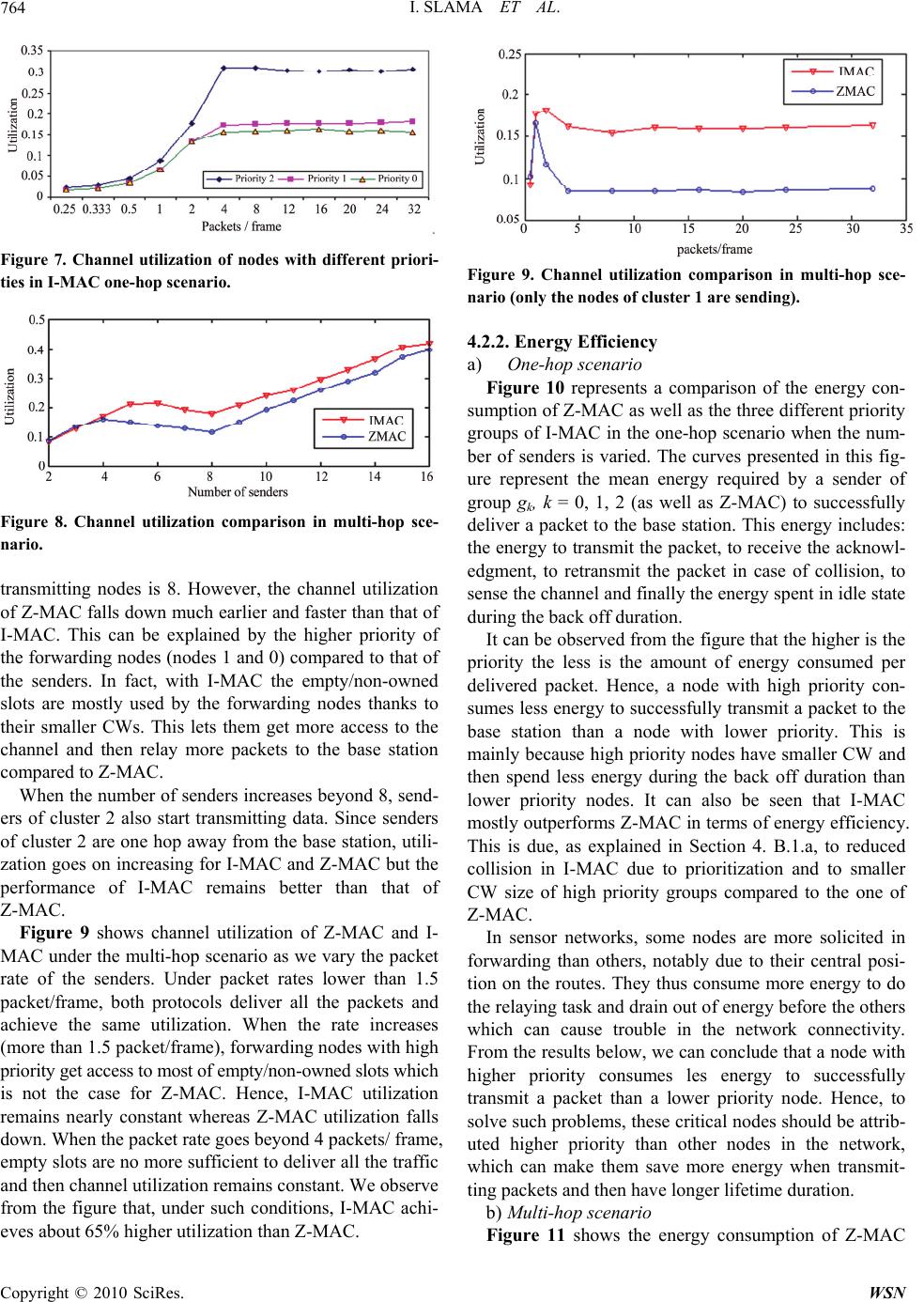 I. SLAMA ET AL. Copyright © 2010 SciRes. WSN 764 Figure 7. Channel utilization of nodes with different priori- ties in I-MAC one-hop scenario. Figure 8. Channel utilization comparison in multi-hop sce- nario. transmitting nodes is 8. However, the channel utilization of Z-MAC falls down much earlier and faster than that of I-MAC. This can be explained by the higher priority of the forwarding nodes (nodes 1 and 0) compared to that of the senders. In fact, with I-MAC the empty/non-owned slots are mostly used by the forwarding nodes thanks to their smaller CWs. This lets them get more access to the channel and then relay more packets to the base station compared to Z-MAC. When the number of senders increases beyond 8, send- ers of cluster 2 also start transmitting data. Since senders of cluster 2 are one hop away from the base station, utili- zation goes on increasing for I-MAC and Z-MAC but the performance of I-MAC remains better than that of Z-MAC. Figure 9 shows channel utilization of Z-MAC and I- MAC under the multi-hop scenario as we vary the packet rate of the senders. Under packet rates lower than 1.5 packet/frame, both protocols deliver all the packets and achieve the same utilization. When the rate increases (more than 1.5 packet/frame), forwarding nodes with high priority get access to most of empty/non-owned slots which is not the case for Z-MAC. Hence, I-MAC utilization remains nearly constant whereas Z-MAC utilization falls down. When the packet rate goes beyond 4 packets/ frame, empty slots are no more sufficient to deliver all the traffic and then channel utilization remains constant. We observe from the figure that, under such conditions, I-MAC achi- eves about 65% higher utilization than Z-MAC. Figure 9. Channel utilization comparison in multi-hop sce- nario (only the nodes of cluster 1 are sending). 4.2.2. Energy Efficiency a) One-hop scenario Figure 10 represents a comparison of the energy con- sumption of Z-MAC as well as the three different priority groups of I-MAC in the one-hop scenario when the num- ber of senders is varied. The curves presented in this fig- ure represent the mean energy required by a sender of group gk, k = 0, 1, 2 (as well as Z-MAC) to successfully deliver a packet to the base station. This energy includes: the energy to transmit the packet, to receive the acknowl- edgment, to retransmit the packet in case of collision, to sense the channel and finally the energy spent in idle state during the back off duration. It can be observed from the figure that the higher is the priority the less is the amount of energy consumed per delivered packet. Hence, a node with high priority con- sumes less energy to successfully transmit a packet to the base station than a node with lower priority. This is mainly because high priority nodes have smaller CW and then spend less energy during the back off duration than lower priority nodes. It can also be seen that I-MAC mostly outperforms Z-MAC in terms of energy efficiency. This is due, as explained in Section 4. B.1.a, to reduced collision in I-MAC due to prioritization and to smaller CW size of high priority groups compared to the one of Z-MAC. In sensor networks, some nodes are more solicited in forwarding than others, notably due to their central posi- tion on the routes. They thus consume more energy to do the relaying task and drain out of energy before the others which can cause trouble in the network connectivity. From the results below, we can conclude that a node with higher priority consumes les energy to successfully transmit a packet than a lower priority node. Hence, to solve such problems, these critical nodes should be attrib- uted higher priority than other nodes in the network, which can make them save more energy when transmit- ting packets and then have longer lifetime duration. b) Multi-hop scenario Figure 11 shows the energy consumption of Z-MAC 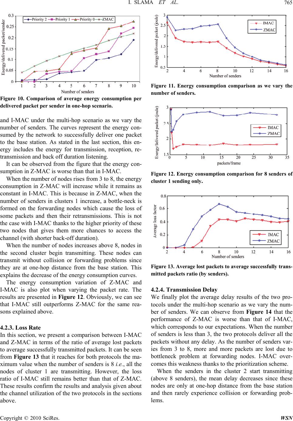 I. SLAMA ET AL.765 Figure 10. Comparison of average energy consumption per delivered packet per sender in one-hop scenario. and I-MAC under the multi-hop scenario as we vary the number of senders. The curves represent the energy con- sumed by the network to successfully deliver one packet to the base station. As stated in the last section, this en- ergy includes the energy for transmission, reception, re- transmission and back off duration listening. It can be observed from the figure that the energy con- sumption in Z-MAC is worse than that in I-MAC. When the number of nodes rises from 3 to 8, the energy consumption in Z-MAC will increase while it remains as constant in I-MAC. This is because in Z-MAC, when the number of senders in clusters 1 increase, a bottle-neck is formed on the forwarding nodes which cause the loss of some packets and then their retransmissions. This is not the case with I-MAC thanks to the higher priority of these two nodes that gives them more chances to access the channel (with shorter back-off duration). When the number of nodes increases above 8, nodes in the second cluster begin transmitting. These nodes can transmit without collision or forwarding problems since they are at one-hop distance from the base station. This explains the decrease of the energy consumption curves. The energy consumption variation of Z-MAC and I-MAC is also plot when varying the packet rate. The results are presented in Figure 12. Obviously, we can see that I-MAC still outperforms Z-MAC for the same rea- sons explained above. 4.2.3. Loss Rate In this section, we present a comparison between I-MAC and Z-MAC in terms of the ratio of average lost packets to average successfully transmitted packets. It can be seen from Figure 13 that it reaches for both protocols the ma- ximum value when the number of senders is 8 i.e., all the nodes of cluster 1 are transmitting. However, the loss ratio of I-MAC still remains better than that of Z-MAC. These results confirm the results and analysis given about the channel utilization of the two protocols in the sections above. Figure 11. Energy consumption comparison as we vary the number of senders. Figure 12. Energy consumption comparison for 8 senders of cluster 1 sending only. Figure 13. Average lost packets to average successfully trans- mitted packets ratio (by senders). 4.2.4. Transmission Delay We finally plot the average delay results of the two pro- tocols under the multi-hop scenario as we vary the num- ber of senders. We can observe from Figure 14 that the performance of Z-MAC is worse than that of I-MAC, which corresponds to our expectations. When the number of senders is less than 3, the two protocols deliver all the packets without any delay. As the number of senders var- ies from 3 to 8, more and more packets are lost due to bottleneck problem at forwarding nodes. I-MAC over- comes this weakness thanks to the prioritization scheme. When the senders in the cluster 2 start transmitting (above 8 senders), the mean delay decreases since these nodes are only at one-hop distance from the base station and then rarely experience collision or forwarding prob- lems. Copyright © 2010 SciRes. WSN  I. SLAMA ET AL. Copyright © 2010 SciRes. WSN 766 Figure 14. Comparison of average delay (in seconds). 5. Conclusions In this paper, we introduced I-MAC, an adaptive hybrid medium access protocol for wireless sensor networks. I-MAC allows sensor nodes that have higher load, for instance because of their forwarding role, to get more chances to access the radio resources. This is achieved through an adaptive prioritization mechanism embedded within the transmission mechanism. Moreover, the life- time of loaded sensors (that usually run out of energy first with usual MAC mechanisms) is prolonged since the pri- oritization mechanism not only shortens their listening period (backoff), but also reduces the collision when they access to the channel. Hence, by combining CSMA and TDMA techniques and introducing prioritization to access the channel, I- MAC becomes more energy efficient, more robust to topology changes and fairer in resource allocation. It gracefully adapts to the level of contention in the net- work and improves the channel utilization as well as the throughput. The performances of the overall MAC scheme were evaluated through simulations over NS2 and the pre- sented results have shown a significant improvement, compared to Z-MAC, mainly in energy efficiency, chan- nel utilization, loss ratio and delay. We aim, in a future work, to achieve further enhance- ments over I-MAC through the proposal of a more dy- namic and efficient mechanism for priority adaptation. We also look forward to implement it over TinyOS to validate the simulation results provided above. 6 . References [1] İ. F. Akyıldız, W. Su, Y. Sankarasubramaniam and E. Çay- ırcı, “Wireless Sensor Networks: A Survey,” IEEE Com- puter Networks, Vol. 38, No. 4, 2002, pp. 393-422. [2] E. Cayirci and P. C. Nar, “PCSMAC: A Power Controlled Sensor-MAC Protocol for Wireless Sensor Networks,” Proceeding of the 2nd European Workshop on Wireless Sensor Network, Istanbul, 2005, pp. 81-92. [3] I. Demirkol, C. Ersoy and F. Alagoz, “MAC Protocols for Wireless Sensor Networks: A Survey,” IEEE Communica- tions Magazine, Vol. 44, No. 4, 2006, pp. 115-121. [4] I. Rhee, A. Warrier, M. Aia and J. Min, “Z-Mac: A Hybrid MAC for Wireless Sensor Networks,” IEEE/ACM Trans- actions on Networking, Vol. 16, No. 3, 2005, pp. 511-524. [5] J. Pan, Y. Hou, L. Cai, Y. Shi and X. Shen, “Topology Control for Wireless Sensor Networks,” Proceeding of the 9th ACM Conference on Mobile Computing and Network- ing, San Diego, 2003, pp. 286-299. [6] A. D. Myers, “Hybrid MAC Protocols for Mobile Ad Hoc Networks,” Ph.D. Thesis, Computer Science, University of Texas, Dallas, 2002. [7] I. Chlamtac, A. Farago, A. Myers, V. Syrotiuk and G. Zaruba, “A Performance Comparison of Hybrid and Con- ventional Mac Protocols for Wireless Networks,” Proceed- ings of Vehicular Technology Conference, Tokyo, Vol. 1, 2000, pp. 201-205. [8] Y. K. Rana, B. H. Ajfandika and S. Jha, “Bandwidth Aware Slot Allocation in Hybrid Mac,” Proceeding of Local Computer Networks, Tampa, 2007, pp. 89-96. [9] S. Li, D. Qian, Y. Liu and J. Tong, “Adaptive Distributed Randomized TDMA Scheduling for Clustered Wireless Sensor Networks,” International Conference on Wireless Communications, Networking and Mobile Computing, Shanghai, 2007, pp. 2688-2691. [10] W. Ye, J. Heidemann and D. Estrin, “An Energy-Efficient MAC Protocol for Wireless Sensor Networks,” Proceeding of the 21st Conference of the IEEE Computer and Commu- nications Societies, New York, Vol. 3, 2002, pp. 1567-1576. [11] T. van Dam and K. Langendoen, “An Adaptive Energy- Efficient MAC Protocol for Wireless Sensor Networks,” Proceeding of the 1st ACM Conference on Embedded Net- worked Sensor Systems, Los Angeles, 2003, pp. 171-180. [12] J. Polastre and D. Culler, “B-Mac: An Adaptive Csma Layer for Low-Power Operation,” Technical Report. cs294-f03/bmac, University of California, 2003. [13] I. Rhee, A. Warrier, J. Min and L. Xu, “DRAND: Dis- tributed Randomized TDMA Scheduling for Wireless Ad-Hoc Networks,” Proceeding of the 7th ACM Interna- tional Symposium on Mobile Ad Hoc Networking and Computing, Florence, 2006, pp. 190-201. [14] O. Bouattay, T. Chahed, M. Frikha and S. Tabbane, “Im- proving Energy Consumption in Ad Hoc Networks Th- rough Prioritization,” Proceedings of Vehicle Technology Conference, Dublin, 2007, pp. 148-153. [15] Y. Wang and I. Henning, “A Deterministic Distributed TDMA Scheduling Algorithm for Wireless Sensor Net- works,” Proceeding of International Conference on Wire- less Communications, Networking and Mobile Computing, Shanghai, 2007, pp. 2759-2762. [16] S. Ramanathan, “A Unified Framework and Algorithms for (T/F/C)DMA Channel Assignment in Wireless Net- works,” Proceeding of 16th Annual Joint Conference of the IEEE Computer and Communications Societies, Kobe, 1997, pp. 900-907. [17] I. Slama, B. Shrestha, B. Jouaber and D. Zeghlache, “DNIB: Distributed Neighborhood Information Based TDMA Scheduling for Wireless Sensor Networks” 68th  I. SLAMA ET AL. Copyright © 2010 SciRes. WSN 767 IEEE Vehicular Technology Conference, Alberta, 2008, pp. 1-5. [18] MAC. http://www.csc.ncsu.edu/faculty/rhee/export/zmac/ software/zmac/zmac.htm.
|