Paper Menu >>
Journal Menu >>
 Journal of Global Positioning Systems (2004) Vol. 3, No. 1-2: 273-279 A Step, Stride and Heading Determination for the Pedestrian Navigation System Jeong Won Kim GNSS Technology Research Center, Chungnam National University, Korea e-mail: kimjw@cnu.ac.kr Tel: + 82-42-821-7709 ; Fax: +82-42-823-5436 Han Jin Jang GNSS Technology Research Center, Chungnam National University, Korea e-mail: handoo01@cnu.ac.kr Tel: + 82-42-821-7709 ; Fax: +82-42-823-5436 Dong-Hwan Hwang GNSS Technology Research Center, Chungnam National University, Korea e-mail: dhhwang@cnu.ac.kr Tel: + 82-42-821-5670 ; Fax: +82-42-823-5436 Chansik Park School of Electrical and Computer Engineering, Chungbuk National University, Korea e-mail: chansp@cbucc.chungbuk.ac.kr Tel: + 82-43-261-3259 ; Fax: +82-43-268-2386 Received: 15 Nov 2004 / Accepted: 3 Feb 2005 Abstract. Recently, several simple and cost-effective pedestrian navigation systems (PNS) have been introduced. These systems utilized accelerometers and gyros in order to determine step, stride and heading. The performance of the PNS depends on not only the accuracy of the sensors but also the measurement processing methods. In most PNS, a vertical impact is measured to detect a step. A step is counted when the measured vertical impact is larger than the given threshold. The numbers of steps are miscounted sometimes since the vertical impacts are not correctly measured due to inclination of the foot. Because the stride is not constant and changes with speed, the step length parameter must be determined continuously during the walk in order to get the accurate travelled distance. Also, to get the accurate heading, it is required to overcome drawbacks of low grade gyro and magnetic compass. This paper proposes new step, stride and heading determination methods for the pedestrian navigation system: A new reliable step determination method based on pattern recognition is proposed from the analysis of the vertical and horizontal acceleration of the foot during one step of the walking. A simple and robust stride determination method is also obtained by analysing the relationship between stride, step period and acceleration. Furthermore, a new integration method of gyroscope and magnetic compass gives a reliable heading. The walking test is preformed using the implemented system consists of a 1-axis accelerometer, a 1-axis gyroscope, a magnetic compass and 16-bit microprocessor. The results of walking test confirmed the proposed method. Key words: Pedestrian navigation system, Step detection, Stride determination, Heading determination 1 Introduction Pedestrian navigation system(PNS) provides velocity and position of a person and can be applied to many other areas such as E-911 service, location based services (LBS), tourism, rescue, military infantry, medical studies, leisure, and navigation for the blind. In PNS, it is necessary to locate the position of the user in any time and any environment. Even GPS is useful personal navigation system, its availability is significantly reduced when a signal is blocked. Also ultra wide band (UWB) and radio frequency identification (RFID) techniques are introduced for personal navigation, but these systems  274 Journal of Global Positioning Systems require dense infrastructure. For these reasons, a self- contained navigation system based on a dead reckoning (DR) principle is of interest (B. Merminod et al, 2002). To locate the position of the PNS user, distance and heading from a known origin have to be measured with an acceptable level of accuracy. In PNS, an accelerometer is used to count the number of steps, which is combined with the stride to obtain the travelled distance. In addition, a magnetic compass or gyroscope is used as a heading sensor. The stride and step are important parameters for PNS dead reckoning algorithm. Many methods have been suggested to detect a step. One such method is to detect the peaks of vertical acceleration, which correspond to the step occurrences because the vertical acceleration is generated by vertical impact when the foot hits the ground. If the vertical impact is larger than given threshold, it is considered as a step. Since the pattern of impact signal depends on type of movement (going up or down stairs, crawling, running etc.) and type of ground over which the person walks (hard or soft surface, sand), the determination of threshold is not so easy for reliable step detection (Ladetto and Merminod, 2002). This paper proposes reliable step detection method based on pattern recognition. From the analysis of the vertical and horizontal acceleration of the foot during one step of the walking, the signal pattern of walking behaviours is obtained. The stride of the walker in PNS is a scale factor in a dead reckoning algorithm. Unlike a scale factor of an odometer in a car navigation system, the stride in PNS is a time- varying parameter (Mar and Leu, 1996). The predetermined stride cannot be used effectively for the distance measurement because the strides of the walker are different according to the human parameters. The stride depends on several factors such as walking velocity, step frequency and height of walker etc. As the stride is not a constant and can change with speed, the step length parameter must be determined continuously during the walk to increase the precision. It is suggested that the stride could be estimated online based on a linear relationship between the measured step frequency and the stride (Levi and Judd, 1996). A real-time step calibration algorithm using a Kalman filter with GPS positioning measurement was also proposed (Jirawimut et al,2003). In this paper, we analyse a relationship between stride, step period and acceleration to obtain simple and robust method of stride determination. A real time online estimation is possible by using only 1-aixis accelerometer. The combination of gyroscope and magnetic compass has already been applied in car navigation (Mar and Leu, 1996) and it might be a very useful heading sensor for pedestrian navigation system. However low cost sensor has important drawbacks: A low cost gyro has large bias and drift error. The magnetic disturbances can be induced fatal compass error. Moreover the error is occurred by an oscillation of human body in a walking behaviour. In this paper, a gyro and a magnetic compass are integrated using Kalman filter for reliable heading of pedestrian. To evaluate the performance of the proposed methods, actual walking test in the indoor environment is conducted. The equipment of walking test is implemented using a 1-aixs accelerometer, a 1-axis gyroscope and a magnetic compass. It consists of two parts: a sensor module and a navigation computer module. The sensor module is attached on the ankle. The step number and stride is computed using the output of the accelerometer on the sensor module. And walking direction is obtained from the gyro and magnetic compass module. The experiments show the very promising results: less than 1% step detection error, less than 5% travelled distance error and less than 5% heading error. 2 Step detection 2.1 Step behaviour analysis of pedestrian A cycle of human walking is composed of two phases: standing and walking phase. The step detection means a recognition of walking phase. The walking phase is divided into a swing phase and a heel-touch-down phase. Each phase is shown in figure 1. Ground Swing phase 1st Swing phase2nd Swing phaseHeel-touch-down phase Fig. 1 A walking behaviour In the 1st swing phase, the foot is located on behind of gravity centre of human body. And the foot is located on front of gravity centre of human body in the 2nd swing phase. The foot accelerated during swing phase. The acceleration is composed of vertical and horizontal components as shown in figure 2, where a, h , g means horizontal acceleration, vertical acceleration and gravity force, respectively. Figure 3 and 4 show motion of leg in the 1st swing phase and the 2nd swing phase respectively.  Kim et al: A Step, Stride and Heading Determination for the Pedestrian Navigation System 275 h g a Ground Fig. 2 Leg of walker a gh − a gh − θ θ θ θ θ cosa θ sin)( gh − θθ sin)(cos gha −− θθ cos)(sin gha −+ θ cos)( gh− θ sina Acc eleration of Vertical direction Acceleration of Horizontal direction directionH tA− )( directionV tA− )( Fig. 3 1st Swing phase directionH tA− )( directionV tA− )( θ θ θ cos)( gh− θ sina a gh − θ θ θ cosa a θ sin)( gh − θθ sincos)(agh −− θθ cossin)( agh +− Acceleration of Vertical direction Acceleration of Horizontal direction Fig. 4 2nd Swing phase The horizontal direction acceleration and vertical direction acceleration during the swing phase is denoted in equation 1, where )(t θ is inclination angle of the leg at time t. )(sin)(cos)()( )(cos)(sin)()( tatghtA tatghtA directionV directionH θθ θθ −−= +−= − − (1) In many researches, a step is declared when the measured directionH tA − )( or directionV tA − )( is larger than the threshold. However since the )(t θ depend on characteristics of walking which is different from each person, it is hard to determine the exact value of threshold of directionH tA − )(or directionV tA − )(. The step number is miscounted when wrongly predetermined threshold is applied. By using the signal pattern of acceleration, this problem can be solved. Typical signal pattern of acceleration is obtained from the computer simulation. We adopted common assumptions that a typical inclination of leg was within the limit of 30 degree ~ 50 degree and a, h have a range of 0.8 ~ 2.3g and 0.6 ~ 2.0g. The pattern of acceleration signal in figure 5 is obtained from 625 times simulations. Fig. 5 Pattern of horizontal and vertical acceleration signal Figure 5 shows the typical pattern of acceleration signal on the swing phase. The acceleration of horizontal direction has 1 positive peak and 1 negative peak in swing phase while the acceleration of vertical direction has 1 negative peak only. The heel-touch-down phase follows the swing phase. A heel-touch-down is impact motion which hits the ground. In heel-touch-down phase, a heel hits the ground at first. And then a sole of foot and toe contact with the ground. When the foot hits the ground, the ground repulses the foot. At this time, impact force acts on the foot. The figure 6 shows the heel-touch-down phase. Im p a ct force Ground Repulsive Power Fig. 6 Heel-touch-down phase Ground Repulsive PowerImpact force Vertical AxisHorizontal Axis Heel-touch-downHeel-touch-down Fig. 7 The typical pattern of signal in heel-touch-down phase 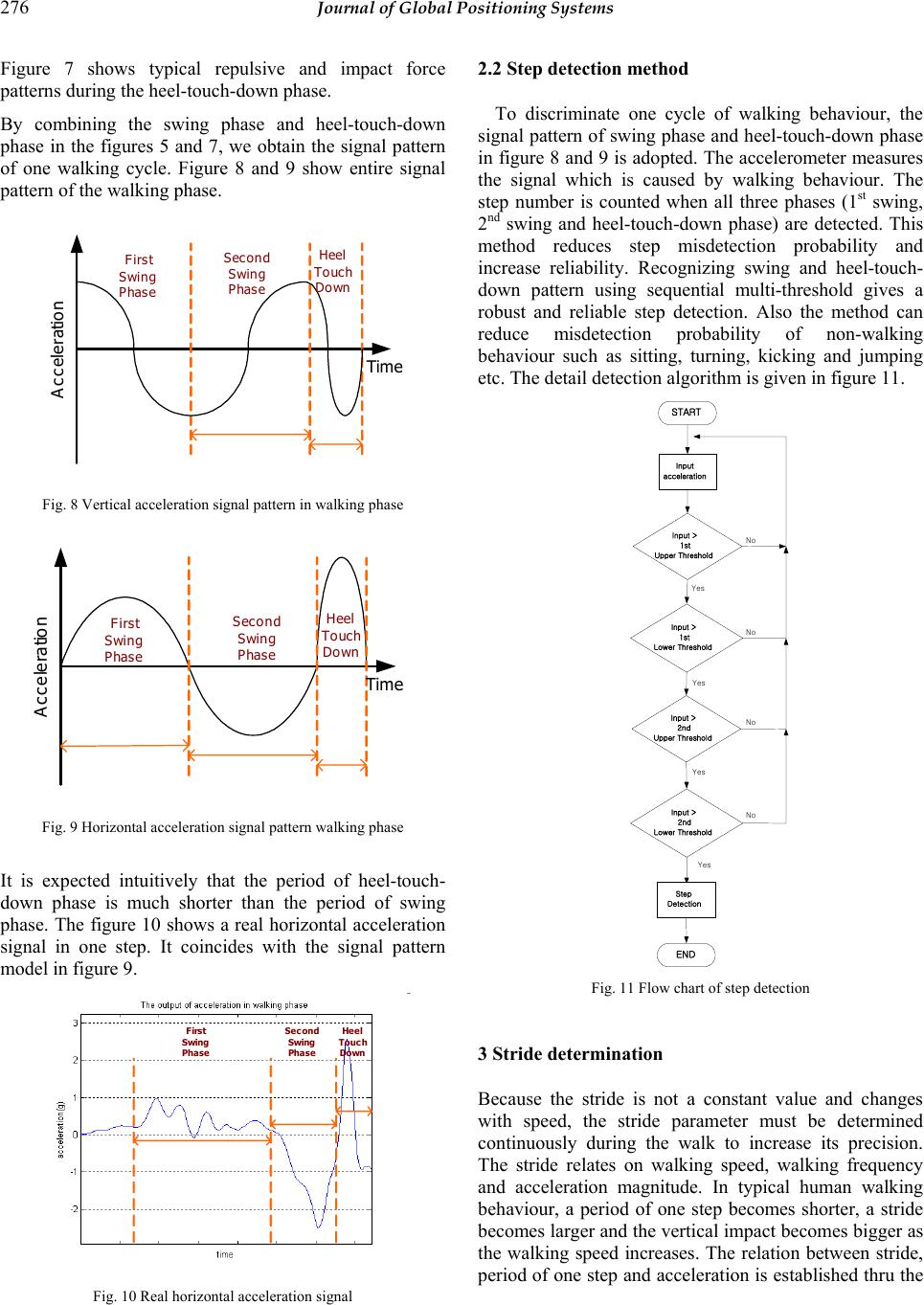 276 Journal of Global Positioning Systems Figure 7 shows typical repulsive and impact force patterns during the heel-touch-down phase. By combining the swing phase and heel-touch-down phase in the figures 5 and 7, we obtain the signal pattern of one walking cycle. Figure 8 and 9 show entire signal pattern of the walking phase. Tim e First Swing Phase Acceleration Second Swing Phase Heel Touch Do wn Fig. 8 Vertical acceleration signal pattern in walking phase Heel Touch Down Time Second Swing Phase Acceleration First Swing Phase Fig. 9 Horizontal acceleration signal pattern walking phase It is expected intuitively that the period of heel-touch- down phase is much shorter than the period of swing phase. The figure 10 shows a real horizontal acceleration signal in one step. It coincides with the signal pattern model in figure 9. Second Swing Phase Heel Touch Down First Swing Phase Fig. 10 Real horizontal acceleration signal 2.2 Step detection method To discriminate one cycle of walking behaviour, the signal pattern of swing phase and heel-touch-down phase in figure 8 and 9 is adopted. The accelerometer measures the signal which is caused by walking behaviour. The step number is counted when all three phases (1st swing, 2nd swing and heel-touch-down phase) are detected. This method reduces step misdetection probability and increase reliability. Recognizing swing and heel-touch- down pattern using sequential multi-threshold gives a robust and reliable step detection. Also the method can reduce misdetection probability of non-walking behaviour such as sitting, turning, kicking and jumping etc. The detail detection algorithm is given in figure 11. START Input acceleration Input > 1st Upper Threshold Input > 1st Lower Threshold Input > 2nd Upper Threshold Input > 2nd Lower Threshold Step Detection END Yes Yes Yes Yes No No No No Fig. 11 Flow chart of step detection 3 Stride determination Because the stride is not a constant value and changes with speed, the stride parameter must be determined continuously during the walk to increase its precision. The stride relates on walking speed, walking frequency and acceleration magnitude. In typical human walking behaviour, a period of one step becomes shorter, a stride becomes larger and the vertical impact becomes bigger as the walking speed increases. The relation between stride, period of one step and acceleration is established thru the 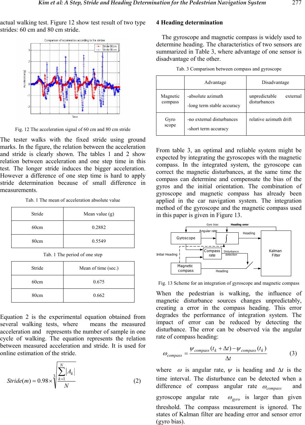 Kim et al: A Step, Stride and Heading Determination for the Pedestrian Navigation System 277 actual walking test. Figure 12 show test result of two type strides: 60 cm and 80 cm stride. Fig. 12 The acceleration signal of 60 cm and 80 cm stride The tester walks with the fixed stride using ground marks. In the figure, the relation between the acceleration and stride is clearly shown. The tables 1 and 2 show relation between acceleration and one step time in this test. The longer stride induces the bigger acceleration. However a difference of one step time is hard to apply stride determination because of small difference in measurements. Tab. 1 The mean of acceleration absolute value Stride Mean value (g) 60cm 0.2882 80cm 0.5549 Tab. 1 The period of one step Stride Mean of time (sec.) 60cm 0.675 80cm 0.662 Equation 2 is the experimental equation obtained from several walking tests, where means the measured acceleration and represents the number of sample in one cycle of walking. The equation represents the relation between measured acceleration and stride. It is used for online estimation of the stride. 31 98.0)( N A mStride N k k ∑ = ×= (2) 4 Heading determination The gyroscope and magnetic compass is widely used to determine heading. The characteristics of two sensors are summarized in Table 3, where advantage of one sensor is disadvantage of the other. Tab. 3 Comparison between compass and gyroscope Advantage Disadvantage Magnetic compass -absolute azimuth -long term stable accuracy unpredictable external disturbances Gyro scope -no external disturbances -short term accuracy relative azimuth drift From table 3, an optimal and reliable system might be expected by integrating the gyroscopes with the magnetic compass. In the integrated system, the gyroscope can correct the magnetic disturbances, at the same time the compass can determine and compensate the bias of the gyros and the initial orientation. The combination of gyroscope and magnetic compass has already been applied in the car navigation system. The integration method of the gyroscope and the magnetic compass used in this paper is given in Figure 13. Gyroscope Magnetic compass Kalman Filter Compass rate Disturbance detection Gyro bias ∫ Angular rateHeading Heading Initial Heading Heading error Fig. 13 Scheme for an integration of gyroscope and magnetic compass When the pedestrian is walking, the influence of magnetic disturbance sources changes unpredictably, creating a error in the compass heading. This error degrades the performance of integration system. The impact of error can be reduced by detecting the disturbance. The error can be observed via the angular rate of compass heading: t ttt kcompasskcompass compass ∆ − ∆ + =)()( ψ ψ ω (3) where ω is angular rate, ψ is heading and t ∆ is the time interval. The disturbance can be detected when a difference of compass angular rate compass ω and gyroscope angular rate gyro ω is larger than given threshold. The compass measurement is ignored. The states of Kalman filter are heading error and sensor error (gyro bias).  278 Journal of Global Positioning Systems 5 Experiments In order to evaluate the performance of the proposed method, the actual walking test is done. The tester is a male aged 26 with 175cm height. The experiments are done at the 4th floor hallway of the engineering building, Chungnam National University, Daejeon, Korea. In the experiments, walking distance determination and heading determination are carried out separately. 5.1 Experimental setup Figure 14 shows the experimental equipments. Sensor Module Navigation Computer Data Acquisition Bluetooth 16-bit Microcontroller MEMORY POWER Communication Compass Ac celermeter Gyro Fig. 14 Experimental equipment The experimental equipments consist of the sensing module, the navigation computer and a data acquisition system (notebook computer). The body-worn sensing module consists of a 16-bit microcontroller, a MEMS accelerometer (ADXL105, Analog device Inc.), a gyroscope (MEMS DMU, Crossbow Inc.), a low-cost digital magnetic compass sensor (CMPS03, ROBOT Electronics Inc.) and other electrical parts (RS-232 converter, DC-DC converter, 9V battery, Bluetooth modem). The sensor module is attached on the ankle with horizontal direction as shown figure 14. 5.2 Experiment of walking distance determination To evaluate performance of the step detection and stride determination algorithm, the tester was asked to walk for pre-determined path (74.2m and 145.6m straight path). Figure 15 shows the output of accelerometer. The true step number of first test is 100 steps and second test 200 steps. The stride is determined using equation 2. The figure 16 and 17 show the strides of left leg. The mean of estimated stride is obtained as 76.1 cm and 75.9 cm respectively. Table 4 shows result of walking test in detail. Fig. 15 The output signal of accelerometer Fig. 16 Estimated stride in 1st test Fig. 17 Estimated stride in 2nd test In the 1st test, the proposed method count step number without loss, while the 2 step detection is lost in 2nd test. The 2 step loss is happened in the last 199th and 200th step where the walking pattern is abruptly changing. The walking distance error is obtained 2.5m, 6.1m respectively. The travelled distance with less than 5% error is obtained. These results verify that the proposed method can measure accurate step numbers and distance.  Kim et al: A Step, Stride and Heading Determination for the Pedestrian Navigation System 279 Tab. 4 The measured walking distance Actual walking behavior Measured step number Measured walking distance Step number 100 step 1st test Walking distance 74.2m 100 step 76.728 m Step number 200 step 2nd test Walking distance 145.6m 198 step 151.674 m 5.3 Experiment of heading determination For heading determination test, the tester walks a straight path of north direction. Figure 18 is result of heading determination test. Fig. 18 Estimated heading by gyro and by integration In the figure, the heading of stand-alone gyro shows oscillatory errors due to the body motion. Kalman filter in the integrated system reduces these errors. The experiments show that the heading of pedestrian can be determined with accuracy of 5 degree. 6 Conclusions and outlook This paper proposes methods to estimate the PNS DR parameters: step, stride and heading. For accurate step detection, we analyse the vertical and horizontal acceleration of the foot during one step of the walking. With this analysis, a new step determination based on the pattern recognition is proposed and the step number can be counted accurately. The relationship between stride and acceleration is derived from actual test. An efficient stride determination method where the stride can be estimated online, so that the user does not need to specify his/her stride, is proposed. The integration scheme of the gyro and magnetic compass is proposed for error compensation of gyro and disturbance rejection of magnetic compass. The experiments using the actual walking tests in indoor shows that the proposed method gives less than 1% step, 5% travelled distance and 5% heading errors. It is expected that the proposed PNS will be very useful navigation system for pedestrian navigation. References Gabaglio, V., (2003): GPS/INS Integration for Pedestrian Navigation Ph. D. dissertation. Institute of Geomatics of the Swiss Federal Institute of Technologye in Lausanne. Mar, J., (1996): Simulations of the positioning accuracy of integrated vehicular navigation systems. In: J.-H. Leu(Eds.): Proc. Inst. Elect. Eng. Radar, Sonar Navigation, vol. 143, Apr., 121–128. Ladetto, Q., (2002): In Step with INS. In: B. Merminod (Eds.):GPS WORLD magazine, 30-38 Quentin Ladetto (2000): On foot navigation: continuous step calibration using both complementary recursive prediction and adaptive Kalman filtering. Proceedings of ION GPS 2000, 1735~1740. Jirawimut, R., (2003): A Method for Dead Reckoning Parameter Correction in Pedestrian Navigation System. In: P. Ptasinski; V. Garaj; F. Cecelja; W.Balachandran (Eds.):IEEE Transactions on Instrumentation and Measurement , Vol. 52, No.1. Levi, R. W., (1996): Dead Reckoning Navigational System using Accelerometer to Measure Foot Impacts. In: T. Judd,(Eds.): United States Patent No. 5,583,776 Lee, S.-W., (2001): Recognition of Walking Behaviours for Pedestrian Navigation. In: K. Mase,(Eds.): Proc. 2001 IEEE Int’l Conf. Control Applications (CCA 01), IEEE Control Systems Soc., Piscataway, N.J., 1152–1155. Gabaglio, V., (1999): Real-time calibration of length of steps with GPS and accelerometers. In: B. Merminod (Eds.):Proceeding of GNSS 99, 599–605. |