Paper Menu >>
Journal Menu >>
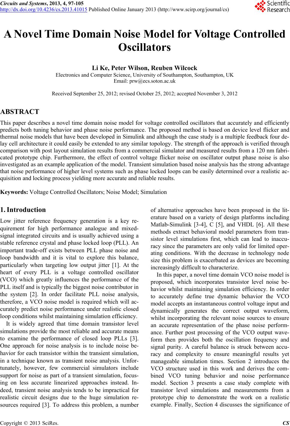 Circuits and Systems, 2013, 4, 97-105 http://dx.doi.org/10.4236/cs.2013.41015 Published Online January 2013 (http://www.scirp.org/journal/cs) A Novel Time Domain Noise Model for Voltage Contr olled Oscillators Li Ke, Peter Wilson, Reuben Wilcock Electronics and Computer Science, University of Southampton, Southampton, UK Email: prw@ecs.soton.ac.uk Received September 25, 2012; revised October 25, 2012; accepted November 3, 2012 ABSTRACT This paper describes a novel time domain noise model for voltage controlled oscillators that accurately and efficiently predicts both tuning behavior and phase noise performance. The proposed method is based on device level flicker and thermal noise models that have been developed in Simulink and although the case study is a multiple feedback four de- lay cell architecture it could easily be extended to any similar topology. The strength of the approach is verified through comparison with post layout simulation results from a commercial simulator and measured results from a 120 nm fabri- cated prototype chip. Furthermore, the effect of control voltage flicker noise on oscillator output phase noise is also investigated as an example application of the model. Transient simulation based noise analysis has the strong advantage that noise performance of higher level systems such as phase locked loops can be easily determined over a realistic ac- quisition and locking process yielding more accurate and reliable results. Keywords: Voltage Controlled Oscillators; Noise Model; Simulation 1. Introduction Low jitter reference frequency generation is a key re- quirement for high performance analogue and mixed- signal integrated circuits and is usually achieved using a stable reference crystal and phase locked loop (PLL). An important trade-off exists between PLL phase noise and loop bandwidth and it is vital to explore this balance, particularly when targeting low output jitter [1]. At the heart of every PLL is a voltage controlled oscillator (VCO) which greatly influences the performance of the PLL itself and is typically the biggest noise contributor in the system [2]. In order facilitate PLL noise analysis, therefore, a VCO noise model is required which will ac- curately predict noise performance under realistic closed loop conditions whilst maintaining simulation efficiency. It is widely agreed that time domain transistor level simulations provide the most reliable and accurate means to examine the performance of closed loop PLLs [3]. One approach for noise analysis is to include noise be- havior for each transistor within the transient simulation, in a technique known as transient noise analysis. Unfor- tunately, however, few commercial simulators include support for noise as part of a transient simulation, focus- ing on less accurate linearized approaches instead. In- deed, transient noise analysis tends to be impractical for realistic circuit designs due to the huge simulation re- sources required [3]. To address this problem, a number of alternative approaches have been proposed in the lit- erature based on a variety of design platforms including Matlab-Simulink [3-4], C [5], and VHDL [6]. All these methods extract behavioral model parameters from tran- sistor level simulations first, which can lead to inaccu- racy since the parameters are only valid for limited oper- ating conditions. With the decrease in technology node size this problem is exacerbated as devices are becoming increasingly difficult to characterize. In this paper, a novel time domain VCO noise model is proposed, which incorporates transistor level noise be- havior whilst maintaining simulation efficiency. In order to accurately define true dynamic behavior the VCO model accepts an instantaneous control voltage input and dynamically generates the correct output waveform, whilst incorporating the relevant noise sources to ensure an accurate representation of the phase noise perform- ance. Further post processing of the VCO output wave- form then provides both the oscillation frequency and signal purity. A careful balance is struck between accu- racy and complexity to ensure meaningful results yet manageable simulation times. Section 2 introduces the VCO structure used in this work and derives the com- bined VCO tuning behavior and noise performance model. Section 3 presents a case study complete with transistor level simulations and measurements from a prototype chip to demonstrate the work on a realistic example. Finally, Section 4 discusses the significance of C opyright © 2013 SciRes. CS 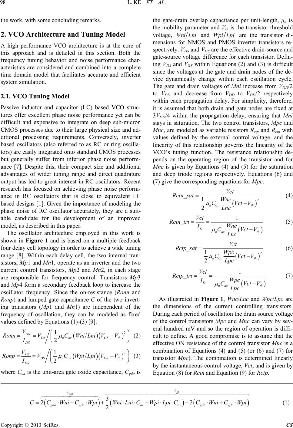 L. KE ET AL. 98 the work, with some concluding remarks. 2. VCO Architecture and Tuning Model A high performance VCO architecture is at the core of this approach and is detailed in this section. Both the frequency tuning behavior and noise performance char- acteristics are considered and combined into a complete time domain model that facilitates accurate and efficient system simulation. 2.1. VCO Tuning Model Passive inductor and capacitor (LC) based VCO struc- tures offer excellent phase noise performance yet can be difficult and expensive to integrate on deep sub-micron CMOS processes due to their large physical size and ad- ditional processing requirements. Conversely, inverter based oscillators (also referred to as RC or ring oscilla- tors) are easily integrated onto standard CMOS processes but generally suffer from inferior phase noise perform- ance [7]. Despite this, their compact size and additional advantages of wider tuning range and direct quadrature output has led to great interest in RC oscillators. Recent research has focused on achieving phase noise perform- ance in RC oscillators that is close to equivalent LC based designs [1]. Given the importance of modeling the phase noise of RC oscillator accurately, they are a suit- able candidate for the development of an improved model, as described in this paper. The oscillator architecture employed in this work is shown in Figure 1 and is based on a multiple feedback four delay cell topology in order to achieve a wide tuning range [8]. Within each delay cell, the two internal tran- sistors, Mp1 and Mn1, operate as an inverter and the two current control transistors, Mp2 and Mn2, in each stage are responsible for frequency control. Transistors Mp3 and Mp4 form a secondary feedback loop to increase the oscillator frequency. Since the on-resistance (Ronn and Ronp) and lumped gate capacitance C of the two invert- ing transistors (Mp 1 and Mn1) are independent of the frequency of oscillation, they can be modeled as fixed values defined by Equations (1)-(3) [9]. 2 GS th VV 1 2 DS DSn ox DS V RonnVCWni Lni I (2) 2 GS th VV 1 2 DS DSn ox DS V RonpVCWpi Lpi I (3) where Cox is the unit-area gate oxide capacitance, Cgdo is the gate-drain overlap capacitance per unit-length, μn is the mobility parameter and Vth is the transistor threshold voltage, WniLni and Wpi are the transistor di- mensions for NMOS and PMOS inverter transistors re- spectively. VDS and VGS are the effective drain-source and gate-source voltage difference for each transistor. Defin- ing VDS and VGS within Equations (2) and (3) is difficult since the voltages at the gate and drain nodes of the de- vice dynamically change within each oscillation cycle. The gate and drain voltages of Mni increase from VDD/2 to VDD and decrease from VDD to VDD/2 respectively within each propagation delay. For simplicity, therefore, it is assumed that both drain and gate nodes are fixed at 3VDD/4 within the propagation delay, ensuring that Mn i stays in saturation. The two control transistors, Mpc and Mnc, are modeled as variable resistors Rctp and Rctn with values defined by the external control voltage, and the linearity of this relationship governs the linearity of the VCO’s tuning function. The resistance relationship de- pends on the operating region of the transistor and for Mnc is given by Equations (4) and (5) for the saturation and deep triode regions respectively. Equations (6) and (7) give the corresponding equations for Mpc. Lpi 2 _1 2nox th Vct Rctn satWnc CVctV Lnc (4) 1 _ Dnox th Vct Rctn triWnc ICVctV Lnc (5) 2 _1 2nox th Vct Rctp satWpc CVctV Lpc (6) 1 _ Dnox th Vct Rctp triWpc ICVctV Lpc (7) As illustrated in Figure 1, Wnc/Lnc and Wpc/Lpc are the dimensions of the current controlling transistors. During each period of oscillation the drain source voltage of the control transistors Mpc and Mnc can vary by sev- eral hundred mV and so the region of operation is diffi- cult to define. A good compromise is to assume that the effective ON resistance of the control transistor Mnc is a combination of Equations (4) and (5) (or (6) and (7) for transistor Mpc). The combination is determined linearly by the instantaneous control voltage, Vct, and is given by Equation (8) for Rctn and Equation (9) for Rctp. in out 3 22 2 C C gdogdooxox gdogdo WniCWpiWniLniCWpi LpiCCWniCWpi C C (1) Copyright © 2013 SciRes. CS 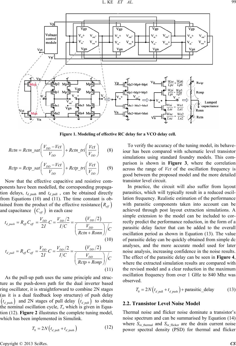 L. KE ET AL. 99 Figure 1. Modeling of effective RC delay for a VCO delay cell. __ DD Vct tn tri VV DD DD VVct RctnRctn satRc (8) _ DD DD VVct RctpRctp satRc V _ DD Vct tp triV (9) Now that the effective capacitive and resistive com- ponents have been modelled, the corresponding propaga- tion delays, td_push and td_pull , can be obtained directly from Equations (10) and (11). The time constant is ob- tained from the product of the effective resistance eff R and capacitance eff C in each case _ 2 2 d DD DD eff efsh fpu VV C II C Rctn t CR 2 DD DD V VC o nnR (10) _ 2 2 DD DD d pulleffeff VV tR C C IIC Rctp 2 DD DD V VC Ronp t (11) As the pull-up path uses the same principle and struc- ture as the push-down path for the dual inverter based ring oscillator, it is straightforward to combine 2N stages (as it is a dual feedback loop structure) of push delay _pushd and 2N stages of pull delay _pulld to obtain the nominal oscillation cycle, To which is given in Equa- tion (12). Figure 2 illustrates the complete tuning model, which has been implemented in Simulink. t _pull _pushdd t t (12) To verify the accuracy of the tuning iour has been compared with schema si pically result in a reduced oscil- la 02TN model, its behave- tic level transistor mulations using standard foundry models. This com- parison is shown in Figure 3, where the correlation across the range of Vct of the oscillation frequency is good between the proposed model and the more detailed transistor level circuit. In practice, the circuit will also suffer from layout parasitics, which will ty tion frequency. Realistic estimation of the performance with parasitic components taken into account can be achieved through post layout extraction simulations. A simple extension to the model can be included to cor- rectly predict the performance reduction, in the form of a parasitic delay factor that can be added to the overall oscillation period as shown in Equation (13). The value of parasitic delay can be quickly obtained from simple dc analyses, and the more accurate model used for later noise analysis, increasing confidence in the noise results. The effect of the parasitic delay can be seen in Figure 4, where the extracted simulation results are compared with the revised model and a clear reduction in the maximum oscillation frequency from over 1 GHz to 840 Mhz was observed. 0_pull _push 2 parasitic_delay dd TNt t (13) 2.2. Transistor Level Noise Model ate a transistor’s y Equation (14) power spectral density (PSD) for thermal and flicker Thermal noise and flicker noise domin noise spectrum and can be summarised b where Sin_thermal and Sin_flicker are the drain current noise Copyright © 2013 SciRes. CS 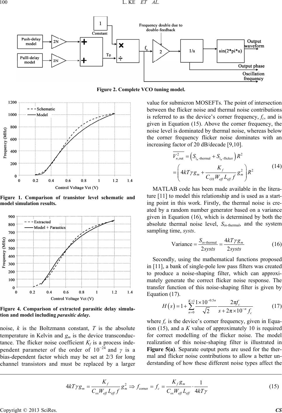 L. KE ET AL. 100 Figure 2. Complete VCO tuning model. l schematic and model simulation results. Figure 1. Comparison of transistor leve delay simula- tion and model including parasitic delay. is the absolute mperature in Kelvin and g is the device transconduc- on MOSEFTs. The point of intersection between the flicker noise and thermal noise contributions Figure 4. Comparison of extracted parasitic noise, k is the Boltzmann constant, T te m tance. The flicker noise coefficient Kf is a process inde- pendent parameter of the order of 10−24 and γ is a bias-dependent factor which may be set at 2/3 for long channel transistors and must be replaced by a larger value for submicr is referred to as the device’s corner frequency, fc, and is given in Equation (15). Above the corner frequency, the noise level is dominated by thermal noise, whereas below the corner frequency flicker noise dominates with an increasing factor of 20 dB/decade [9,10]. 22 ,out-thermal -flicker nn ni i VSS R 22 4f mm OX eff eff K kT ggR CWLf (14) MATLAB code has been made available in the litera- ture [11] to model this relationship and is used as a start- ing point in this work. Firstly, the thermal noise is cre- ated by a random number generator based on a variance given in Equation (16), which is determined by both the absolute thermal noise level, Sin-thermal, and the system sampling time, systs. -thermal 22 in m 4 Variance SkTg s ysts systs (16) Secondly, using the mathematical fun in [11], a bank of single-pole low pass filters was created to ctions proposed produce a noise-shaping filter, which can approxi- mately generate the correct flicker noise response. The transfer function of this noise-shaping filter is given by Equation (17). 0.5 12π 110 1 n K c f Hs 02π10 2n nc s f (17) where fc is the device’s corner frequency, giv tion (15), and a K value of approximately 10 is required en in Equa- for correct modelling of the flicker noise. The model realization of this noise-shaping filter is illustrated in Figure 5(a). Separate output ports are used for the ther- mal and flicker noise contributions to allow a better un- derstanding of how these different noise types affect the 2 corner 1 44 ffm mmc ox effeffox effeff g kT ggff CW LfCW LkT KK (15) Copyright © 2013 SciRes. CS  L. KE ET AL. 101 (a) (b) Figure 5. Simulink model of thermal and flicker noise sources (a) and PFD of single device noise (b). , confirming g model and device level noise model the final stage is to combine oth the tun- VCO noise as a whole. A power spectral density com- parison of the single device noise model and a simulation Spectre is shown together in Figure 5(b) in correct operation of the model at this level. Combined VCO Noise and Tuning Model Having developed both the VCO level tunin both aspects in a model which will predict b ing and noise performance of the VCO. The first chal- lenge in achieving this is to relate the noise quantity, currently in the form of current (A) to the VCO time do- main jitter (s) and frequency domain phase noise (dBc/ Hz@offset). The jitter, Δtd occurring within a single propagation delay can be calculated by integrating the noise current, in(t), over the time interval td and dividing by the pull-up/push-down current, I, as described by Equations (18) and (19) [10]. The propagation delay and pull-up/push-down current can be obtained directly from the model in Figure 2. 0 1d d t nn vitt C (18) 0 1d d t dn itt II (19) It is possible at this stage to combine 4N noise gen- erators from the previous model where each delay cell has four transistors (Mn1, Mn2, Mp5, Mp6). However, with each noise block re- quiring 11 transfer functions for fli the total of 44 transfer functions would degrade the simulation efficiency. Furthermore, having to adjust the model structure as the number of stages sirable, so instead N should be an input variable. For this re n v tC section for an N stage VCO cker noise generation, changes is unde- ason, three simplifications are performed on the model to improve efficiency. First, it is possible to combine pairs of noise contributors into one lumped transistor by making the reasonable assumption that the inverting and control transistors share the same dimensions. This halves the number of noise generators, which greatly enhances the efficiency of the model. Secondly, assume- ing a lumped transistor noise model it is important to establish the relationship between the control voltage and the trans-conductance of the lumped transistor as this will have an impact on its noise characteristics. As a re- sult of this, the altered noise profile of this lumped tran- sistor can be determined by Equations (20) and (21) where gm_lump is its trans-conductance. _mlumpnoxth Wni g CVctV Lni (20) _1 4 fmlump c ox Kg fCWniLni kT (21) Thirdly, for short td time intervals it can be assumed that the noise current stays at a constant value within the interval meaning that Equation (19) can be reduced to Equation (22). If the change in noise current within the time interval is noticeable, however, th amplitude spread is known to be pro length of the time interval and trans-conductance, but inversely proportional to the load capa thermore, it is known that the jitter amplitude spread is pr is so-called jitter portional to the citance [10]. Fur- oportional with the order of device’s corner frequency allowing Equation (22) to be extended to the more gen- eral case of Equation (23). 0 1d d t n dn d i tittt I I (22) _log1 0 dmlump n dd tg fc it tt t IC (23) Based on the above refinement the proposed jitter generator is shown in Figure 6 which is a combination of the propagation delay generator and the noise generator. The accuracy of this model can be attributed to the noise current, the push current and the len tion delay all being a function of the control voltage, rather than assuming independence from this important gth of the propaga- Copyright © 2013 SciRes. CS  L. KE ET AL. 102 circuit parameter. The resulting full VCO model results in 2N PMOS and 2N NMOS based noise gen an N stage oscillator. Summing all squares of the noise co hows the developed model phase noise re- e case study circuit dimensions based on tions of the fully extracted erators for ntributors gives the total noise which is then trans- formed into the jitter value. In order to determine the phase noise, the instantaneous oscillation frequency and output phase is also available at the model output. The phase noise, which is the parameter of ultimate interest, can be approximated by the power spectral density (PSD) function of extra phase. 3. Results In this section the novel VCO noise model is tested and compared to results from an industry standard simulator. A case study circuit was designed for this purpose with the dimensions given in Table 1, which refer to the schematic of Figure 1. Phase Noise Simulations Figure 7(a) s sults using th just flicker noise. Here the new model is shown to agree well with post layout simula circuit. Both curves have a roll-off factor of 30 dB/dec- ade, which demonstrates that the device flicker noise is being modeled correctly. For further analysis the noise source in the model was changed from flicker to thermal, which correctly resulted in a shallower roll-off factor of 20 dB/decade [10] as shown in Figure 7(b). The behave- ioral models in both cases took 1 minutes and 45 seconds to generate, whereas the transistor level simulations took from 3 - 4 minutes. Although this demonstrates an effi- ciency saving of 50% - 60%, it is important to point out, as discussed in Section 1, that the real benefit of the pro- posed model is its suitability for simulating the noise of complex systems such as PLLs, due to its time domain nature. It is well known that flicker noise in the VCO control voltage plays a more significant role than any other noise source in the oscillator circuit [10] which makes it an interesting aspect to investigate with the proposed model. Within the current mirror structure that generates the control voltage, the diode connected transistor is the ma- jor noise contributor and can be modeled by another in- stance of the device noise model. In order to translate the Figure 6. Combination of the noise generator with the VCO behavioral model. and thermal noise (a) (b) Figure 7. Comparison between the proposed Simulink model and Spectre based r esults for flicker noise (a) (b) induced phase noise. Copyright © 2013 SciRes. CS  L. KE ET AL. 103 current noise of the device model to control voltage noise is it multiplied by the transistor’s output resistance which is obtained through a simple DC simulation. Table 2 shows four example designs where the current mirror transistors are varied, keeping all other design parameters the same. For the purposes of fair comparison, the differential control voltages generated from the con- trol module were designed to be almost identical (Vct = 1.2 V), resulting in almost identical oscillation frequent- cies. However, a significant difference is apparent for the phase noise performances of these four design examples, which are shown in Figure 8. As in the previous design example, both the circuit simulator based post layout simulation results and the pro VCO output phase noise without paying a penalty in simulation time. The recommended design going forward would be Design 3 which achieves excellent phase noise without the compromise of a large transistor area and correspondingly large gate capacitance, which could cause stability problems in a larger system. 4. Prototype Chip To verify the proposed VCO model further, the VCO design example of the previous section with the recom- mended control module sizing of Design 3 was realized with a prototype chip fabricated on a standard0 nm re 9(a) shows the layut view highlighted, and Figure 9(b) 0 are consis- results and simulation results posed model results were 1.2 V CMOS process. Figu of the chip with the VCO obtained. The phase noise results obtained from these wo methods agree strongly for these four analytical de- shows the die being probed on a high speed wafer prob- t sign cases, confirming the accuracy of the proposed VCO model. As expected, the results clearly show that lowering the transistor output resistance through a greater W/L ratio is an essential requirement for reducing the VCO output phase noise, highlighting the well-known trade-off be- tween power and noise performance. In this example the proposed model has allowed accurate analysis of the 12 o ing station. Bench tests used an Agilent E4443A 3 Hz-6.7 GHz spectrum analyser and gave the phase noise plot in Figure 10. A battery was used for the power source to ensure very low noise from the supply. The phase noise spectrum shows a roll off of −30 dBc/Hz/decade, indicating that flicker noise is dominant in the design. The results shown in Figure 1 tent with the modeling Figure 8. Phase noise with different transistor dimensions. Table 1. Transistor dimensions of design example. Transistor: W/L (mm): Transistor: W/L (mm): Table 2. Varying the control current mirror transistors in four design examples. Design 3 Design 4 DeviceDesign 1 Design 2 Mcn 0.15 µm/0.13 µm2 µm/0.4 µm Mp1, Mp2 100/0.4 Mn1, Mn2 64/0.4 Mp3, Mp4 100/0.4 Mn3, Mn4 32/0.4 Mp5, Mp6 199/0.4 Mn5, Mn6 32/0.4 16 µm/0.4 µm 160 µm/1 µm Mcp 0.45 µm/0.13 µm6 µm/0.4 µm gds of Mcp 23 µ 44.77 µ 48 µm/0.4 µm 480 µm/1 µm 374.4 µ 849.2 µ Copyright © 2013 SciRes. CS  L. KE ET AL. 104 shown in Figure 7(a). It is important to investigate the phase noise with different tuning voltages and measured results for this parameter are summarized within Tab le 3 along with the predicted results from the developed model. The results are very encouraging, given the difficulty in accurately measuring noise in practice. The discrepan- cies at 100 kHz offset and the ramp in the spectrum un- der 100 kHz are attributed to the noise of the DC voltage source, which was not included in the model. The dis- crepancy towards the lower end of the frequency range with 10 MHz offset is due to the noise floor of the testing platform. Elsewhere, the variations of phase noise be- tween the simulated and measurement are generally less than 5 dB. 5. Conclusion One of the most challenging problems when simulating PLLs is obtaining accurate jitter and phase noise per- formance from transient simulations. VCOs largely inate the noise performanc resenal- lengise anerfoom ain s. The key advantage of this approach is its application in hig PLL system simunce cocial sofdom sransnalow- ever thso thefit of inula- en extensively validated through csonth laulad mre To onstrat cont vol inv anlinesvoln- signers to correctly and efficiently predict true time do- main noise performance in VCOs allowing them to make informed decisions about transistor sizing as a result. (a) dom p e of PLLs and this paper ts a novel VCO noise model to address this ch e, which facilitates efficient analysis of phase no d tuning prmance frtime domsimulation her levellations simmer tware selupports tient noise aysis, h ere is ale bencreased simtion effi ciency with reduced simulation times. The accuracy of the predicted phase noise performance using the pro- posed model has be ompari with boextractedyout simtions an easud results from a 120 nm CMOS prototype chip. dem rol e an application tage flicker noi of t se on VC he model, the e O output phase n ffect of oise has beenestigatedd guide for the tage co trol module proposed as a result. Compared with alterna- tive approaches, the proposed model enables circuit de- (b) Figure 9. Prototype chip layout view (a) and probe station setup (b). Figure 10. Measured phase noise at 744 MHz. se noise over the full tuning range. Measured/simulated phase noise (dBc/Hz ) Table 3. Measured and simulated pha Effective control voltage (V) Oscillation frequency (MHz) 100 kHz offset 1 MHz offset 10 MHz offset 1.2 743.6 −82.23/−80.09 −112.8/−110.91 −140.25/−140.36 1.06 721.7 −73.1/ 0.93 685.2 −69.38 0.8155 646.1 −87.2 0.7157 569.8 −75.56 0.619 455.7 −78.27 0 −81.02 −112.25/−111.34 −140.06/−141.78 /−82.82 −112.55/−112.92 −139.38/−142.48 4/−83.31 −112.26/−113.19 −139.66/−142.51 /−84.55 −109.14/−113.43 −137.81/−143.01 /−84.78 −109.45/−114.39 −136.00/−144.32 9 −79.42/−85.37 −107.35/−114.71 −134.75/−145.8 164.9 −81.8/−86.91 −109.32/−115.85 −135.28/−145.2 97.55 −83.17/−87.32 −110.66/−116.32 −136.6/−145.19 .5 288. 0.414 0.353 Copyright © 2013 SciRes. CS  L. KE ET AL. 105 REFERENCES [1] Z. H. Gao, Y. C. Li and S. L. Yan, “A 0.4 ps-RMS-Jitter 1 - 3 GHz Ring Oscillator PLL Using Phase-Noise Pre- amplification,” IEEE Journal of Solid-State Circuits, Vol. 43, No. 9, 2008, pp. 2079-2089. doi:10.1109/JSSC.2008.2001873 [2] G. Manganaro, S. UngKwak, S. H. Cho and A. Pulin- cherry, “A Behavioral Modelling Approach to the Design a Low Jitter Clock Source,” IEEE Transactions on Cir- cuit and Systems II, Vol. 50, No. 11, 2003, pp. 804-814. [3] L. Bizjak, N. Da Dalt, P. Thurner, R. Nonis, P. Paletri and L. Selmi, “Comprehensive Behavioral Modeling of Con- ventional and Dual-Tunig PLLs,” IEEE Transactions on Circuit and System I, Vol. 55, No. 6, 2008, pp. 1628- 1638. [4] S. Brigati, F. Francesconi, A. Malvasi, A. Pesucci and M. Polerri, “Modeling of Franctional-N Division Frequency Synthesizers with Simulink and Matlab,” The 8th IEEE International Conference on Electronics, Circuits and Systems, Vol. 2, 2001, pp. 1081-1084. [5] M. H. Perrott, “Fast and Accurate Behaviotal Simulation of Fractional-N Frequency Synthesizers and Other PLL/ DLL Circuits,” Proceedings of the 39th annual Design Automation Conference, New York, 10-1 June 2002, pp. 498-503. n Simulation and Modeling of Phase Noise of an RF Oscillator,” IEEE Transactions on Circuit and Systems I, Vol. 52, No. 4, 2005, pp. 723-733. [7] D. A. Badillo and S. Kiaei, “A Low Phase Noise 2.0 V 900 MHz CMOS Voltage Controlled Ring Oscillator,” Proceedings of the 2004 International Symposium on Circuits and Systems, Vol. 4, 2004, p. 533 [8] K. Li, R. Wilcock and P. Wilson, “Improved 6.7 GHz CMOS VCO Delay Cell with up to Seven Octave Tuning Range,” IEEE International Symposium on Circuits and Systems, Seattle, 18-21 May 2008, pp. 444-447. [9] R. J. Baker, “CMOS Circuit Design, Layout and Simula- tion,” 2nd Edition, IEEE Press, Wiley, Hoboken008. d 4 [6] R. B. Staszewski, C. Fernando and P. T. Balsara, “Event- Drive , 2 oi:10.1109/9780470547106 [10] A. A. Abidi, “Phase Noise and Jitter in CMOS Ring Os- cillators,” IEEE Journal of Solid-State Circuits, Vol. 41, No. 8, 2006, pp. 1803-1816. doi:10.1109/JSSC.2006.876206 [11] S. C. Terry, J. Blalock, J. M. Rochelle, M. N. Ericson and S. D. Caylor, “Time-Domain Noise Analysis of Lineat Time-Invariant and Linear Time-Variant Systems Using MATLAB and HSPICE,” IEEE Transactions on Nuclear Science, Vol. 52, No. 3, 2005, pp. 1418-1422. Copyright © 2013 SciRes. CS |