Paper Menu >>
Journal Menu >>
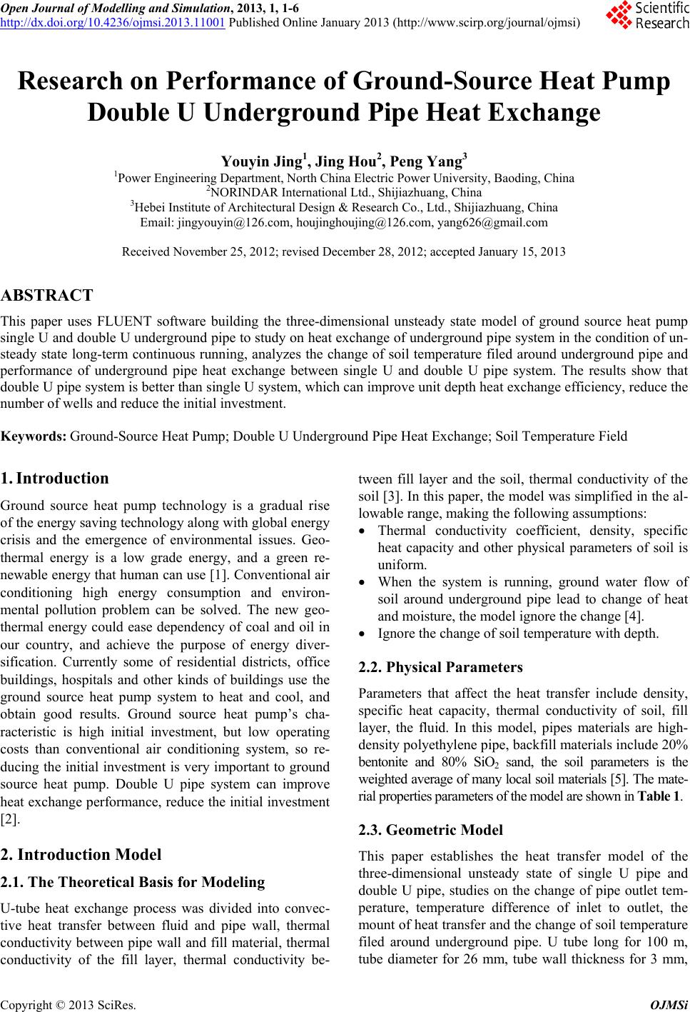 Open Journal of Modelling and Simulation, 2013, 1, 1-6 http://dx.doi.org/10.4236/ojmsi.2013.11001 Published Online January 2013 (http://www.scirp.org/journal/ojmsi) Research on Performance of Ground-Source Heat Pump Double U Underground Pipe Heat Exchange Youyin Jing1, Jing Hou2, Peng Yang3 1Power Engineering Department, North China Electric Power University, Baoding, China 2NORINDAR International Ltd. , Shi jia zhuang, China 3Hebei Institute of Architectural Design & Research Co., Ltd., Shijiazhuang, China Email: jingyouyin@126.com, houjinghoujing@126.com, yang626@gmail.com Received November 25, 2012; revised December 28, 2012; accepted January 15, 2013 ABSTRACT This paper uses FLUENT software building the three-dimensional unsteady state model of ground source heat pump single U and double U underground pipe to study on heat exchange of underground pip e system in the condition of un- steady state long-term continuous running, analyzes the change of soil temperature filed around underground pipe and performance of underground pipe heat exchange between single U and double U pipe system. The results show that double U pipe system is better than single U system, which can improve unit depth heat exchange efficiency, reduce the number of wells and reduce the initial investment. Keywords: Ground-Source Heat Pump; Double U Unde rground Pipe Heat Exchange; Soil Temperature Field 1. Introduction Ground source heat pump technology is a gradual rise of th e en erg y savi ng techno logy along w ith glob al en erg y crisis and the emergence of environmental issues. Geo- thermal energy is a low grade energy, and a green re- newable energy that human can use [1]. Conventional air conditioning high energy consumption and environ- mental pollution problem can be solved. The new geo- thermal energy could ease dependency of coal and oil in our country, and achieve the purpose of energy diver- sification. Currently some of residential districts, office buildings, hospitals and other kinds of buildings use the ground source heat pump system to heat and cool, and obtain good results. Ground source heat pump’s cha- racteristic is high initial investment, but low operating costs than conventional air conditioning system, so re- ducing the initial investment is very important to ground source heat pump. Double U pipe system can improve heat exchange performance, red uce the initial investment [2]. 2. Introduction Model 2.1. The Theoretical Basis for Modeling U-tube heat exchange process was divided into convec- tive heat transfer between fluid and pipe wall, thermal conductivity between pipe wall and fill material, thermal conductivity of the fill layer, thermal conductivity be- tween fill layer and the soil, thermal conductivity of the soil [3]. In this paper, the model was simplified in the al- lowable range, making the following assumptions: Thermal conductivity coefficient, density, specific heat capacity and other physical parameters of soil is uniform. When the system is running, ground water flow of soil around underground pipe lead to change of heat and moisture, the model ignore the change [4]. Ignore the change of soil temperature with depth. 2.2. Physical Parameters Parameters that affect the heat transfer include density, specific heat capacity, thermal conductivity of soil, fill layer, the fluid. In this model, pipes materials are high- density polyethylen e pipe, backfill materials in clude 20% bentonite and 80% SiO2 sand, the soil parameters is the weighted average of many local soil materials [5]. The mate- rial propertie s paramet ers of the m odel are shown in Table 1. 2.3. Geometric Model This paper establishes the heat transfer model of the three-dimensional unsteady state of single U pipe and double U pipe, studies on the change of pipe outlet tem- perature, temperature difference of inlet to outlet, the mount of heat transfer and the change of soil temperature filed around underground pipe. U tube long for 100 m, tube diameter for 26 mm, tube wall thickness for 3 mm, C opyright © 2013 SciRes. OJMSi 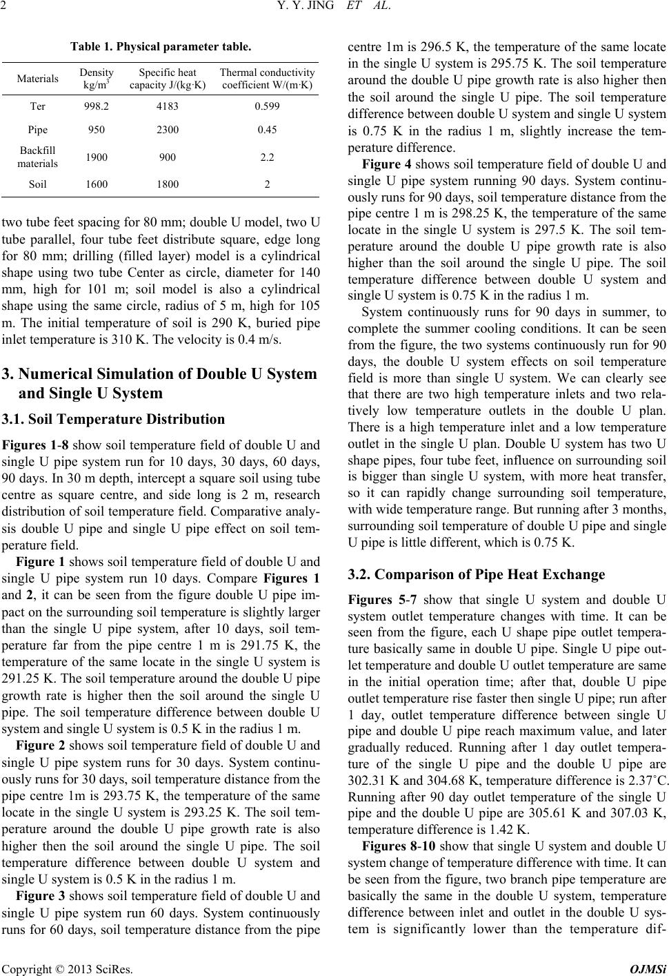 Y. Y. JING ET AL. 2 Table 1. Physical parameter table. Materials Density kg/m3 Specific heat capacity J/(kg·K) Thermal conductivity coefficient W/(m·K) Ter 998.2 4183 0.599 Pipe 950 2300 0.45 Backfill materials 1900 900 2.2 Soil 1600 1800 2 two tube feet spacing for 80 mm; double U model, two U tube parallel, four tube feet distribute square, edge long for 80 mm; drilling (filled layer) model is a cylindrical shape using two tube Center as circle, diameter for 140 mm, high for 101 m; soil model is also a cylindrical shape using the same circle, radius of 5 m, high for 105 m. The initial temperature of soil is 290 K, buried pipe inlet temperature is 310 K. The velocity is 0.4 m/s. 3. Numerical Simulation of Double U System and Single U System 3.1. Soil Temperature Distribution Figures 1-8 show soil temperature field of double U and single U pipe system run for 10 days, 30 days, 60 days, 90 days. In 30 m depth, intercept a square soil using tube centre as square centre, and side long is 2 m, research distribution of soil temperature field. Comparative analy- sis double U pipe and single U pipe effect on soil tem- perature field. Figure 1 shows soil temperature field of double U and single U pipe system run 10 days. Compare Figures 1 and 2, it can be seen from the figure double U pipe im- pact on the surrounding so il temperature is slightly larg er than the single U pipe system, after 10 days, soil tem- perature far from the pipe centre 1 m is 291.75 K, the temperature of the same locate in the single U system is 291.25 K. The soil temperature around the double U pipe growth rate is higher then the soil around the single U pipe. The soil temperature difference between double U system and single U system is 0.5 K in the radius 1 m. Figure 2 shows soil temperature field of double U and single U pipe system runs for 30 days. System continu- ously runs for 30 days, soil temperature distance from the pipe centre 1m is 293.75 K, the temperature of the same locate in the single U system is 293.25 K. The soil tem- perature around the double U pipe growth rate is also higher then the soil around the single U pipe. The soil temperature difference between double U system and single U system is 0.5 K in the radius 1 m. Figure 3 shows soil temperature field of double U and single U pipe system run 60 days. System continuously runs for 60 days, soil temperature distance from the pipe centre 1m is 296.5 K, the temperature of the same locate in the single U system is 295.75 K. The soil temperature around the double U pipe growth rate is also higher then the soil around the single U pipe. The soil temperature difference between double U system and single U system is 0.75 K in the radius 1 m, slightly increase the tem- perature difference. Figure 4 shows soil temperature field of double U and single U pipe system running 90 days. System continu- ously runs for 90 days, soil temperature distance from the pipe centre 1 m is 298.25 K, the temperature of the same locate in the single U system is 297.5 K. The soil tem- perature around the double U pipe growth rate is also higher than the soil around the single U pipe. The soil temperature difference between double U system and single U system is 0.75 K in the radius 1 m. System continuously runs for 90 days in summer, to complete the summer cooling conditions. It can be seen from the figure, the two systems continuously run for 90 days, the double U system effects on soil temperature field is more than single U system. We can clearly see that there are two high temperature inlets and two rela- tively low temperature outlets in the double U plan. There is a high temperature inlet and a low temperature outlet in the single U plan. Double U system has two U shape pipes, four tube feet, influence on surrounding soil is bigger than single U system, with more heat transfer, so it can rapidly change surrounding soil temperature, with wide temperature range. But running after 3 months, surrounding soil temperature of double U pipe and single U pipe is little different, which is 0.75 K. 3.2. Comparison of Pipe Heat Exchange Figures 5-7 show that single U system and double U system outlet temperature changes with time. It can be seen from the figure, each U shape pipe outlet tempera- ture basically same in double U pipe. Single U pipe out- let temperature and double U outlet temperature are same in the initial operation time; after that, double U pipe outlet temperature rise faster then single U pipe; run after 1 day, outlet temperature difference between single U pipe and double U pipe reach maximum value, and later gradually reduced. Running after 1 day outlet tempera- ture of the single U pipe and the double U pipe are 302.31 K and 304.68 K, temperature difference is 2.37˚C. Running after 90 day outlet temperature of the single U pipe and the double U pipe are 305.61 K and 307.03 K, temperature difference is 1.42 K. Figures 8-10 show that single U system and double U system change of temperature difference with time. It can be seen from the figure, two branch pipe temperature are basically the same in the double U system, temperature difference between inlet and outlet in the double U sys- tem is significantly lower than the temperature dif- Copyright © 2013 SciRes. OJMSi 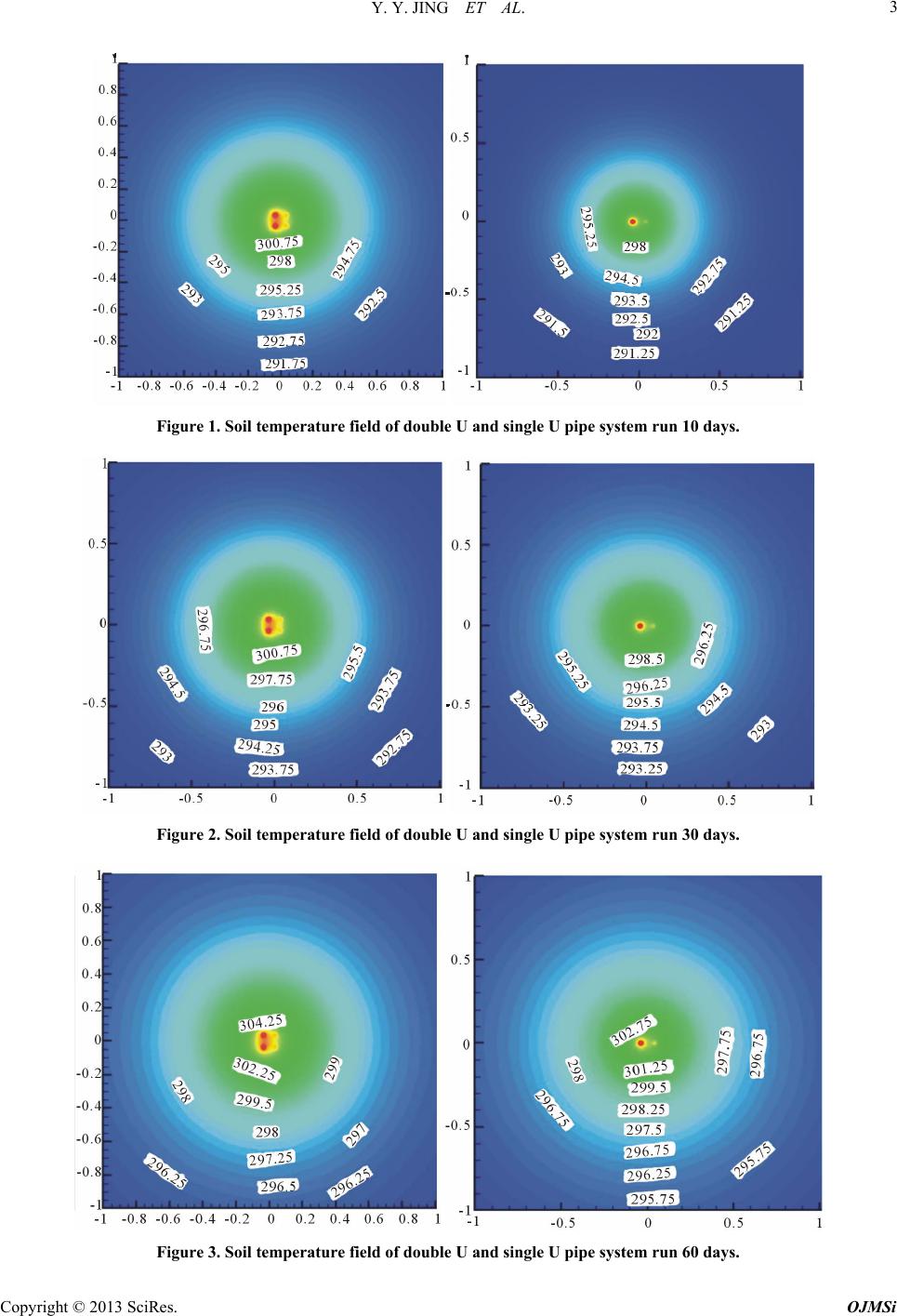 Y. Y. JING ET AL. Copyright © 2013 SciRes. OJMSi 3 Figure 1. Soil temperature field of double U and single U pipe system run 10 days. Figure 2. Soil temperature field of double U and single U pipe system run 30 days. Figure 3. Soil temperature field of double U and single U pipe system run 60 days.  Y. Y. JING ET AL. 4 Figure 4. Soil temperature field of double U and single U pipe system run 90 days. 290 292 294 296 298 300 302 02040 60 80100120 time(min) temperature(K) singleU doubleU1 doubleU2 Figure 5. Run 2 h the change of pipe outlet temperature. 299 300 301 302 303 304 305 246810 12 14 1618 20 22 24 time(h) temperature(K) singleU doubleU1 doubleU2 Figure 6. Run 2 h - 24 h the change of pipe outlet tempera- ture. 302 303 304 305 306 307 308 0 102030405060708090 time(d) temperature(K) singleU doubleU1 doubleU2 Figure 7. Run 1 d - 90 d the change of pipe outlet tempera- ture. 8 10 12 14 16 18 20 0 2040608010012 time(min) temperature(K) 0 singleU doubleU1 doubleU2 Figure 8. Run 2 h the chan ge of pipe temperature difference. 4 5 6 7 8 9 10 11 12 24681012 1416 18 2022 24 time(h) temperature(K) singleU doubleU1 doubleU2 Figure 9. Run 2 h - 24 h the change of pipe temperature difference. 2 3 4 5 6 7 8 0 102030405060708090 ti me(d) tem per atu re(K) sin g leU doubleU1 doubleU2 single U doubleU2doubleU1 Figure 10. Run 2 h - 24 h the change of pipe temperature difference. Copyright © 2013 SciRes. OJMSi 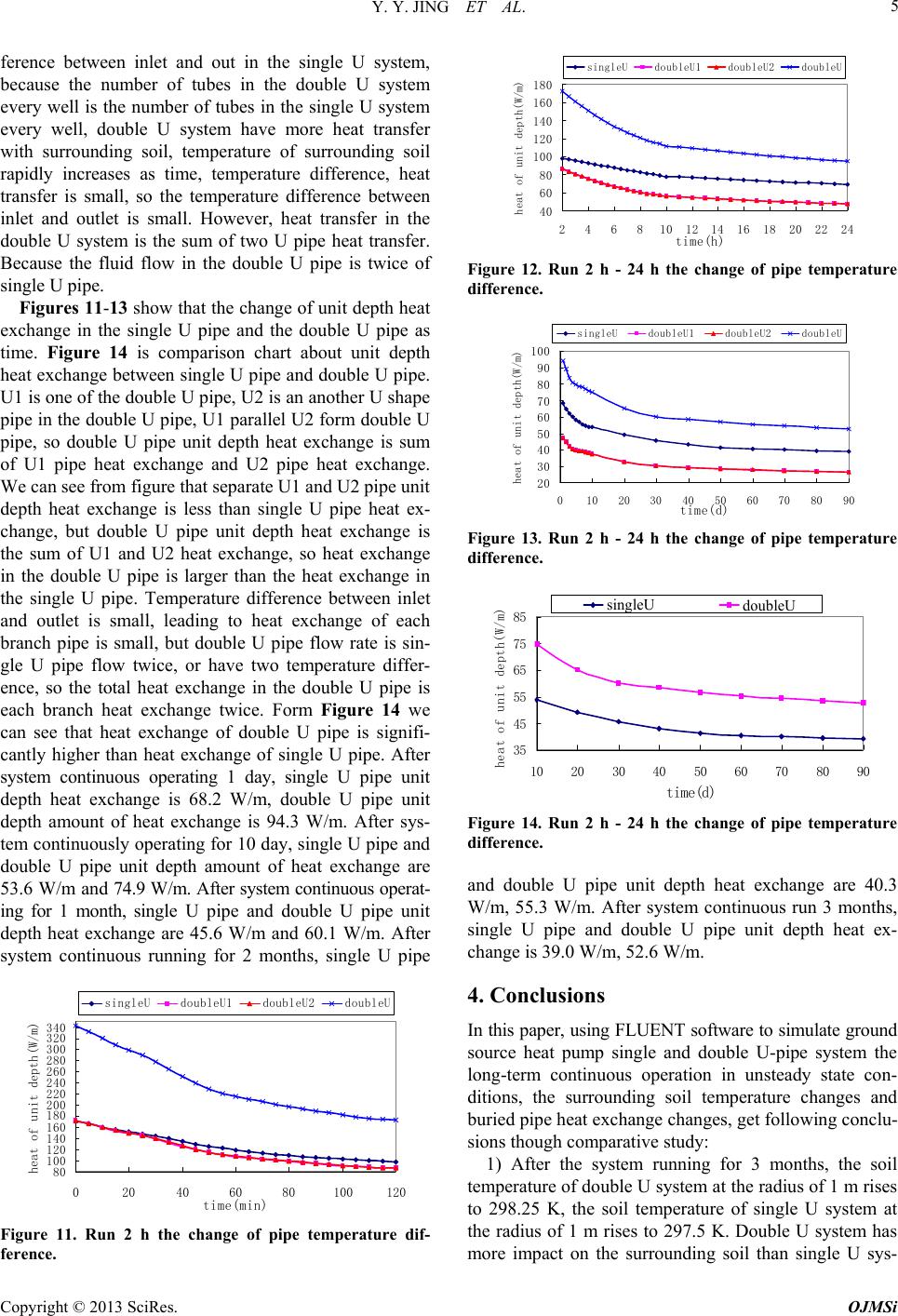 Y. Y. JING ET AL. 5 ference between inlet and out in the single U system, because the number of tubes in the double U system every well is the number of tubes in the single U system every well, double U system have more heat transfer with surrounding soil, temperature of surrounding soil rapidly increases as time, temperature difference, heat transfer is small, so the temperature difference between inlet and outlet is small. However, heat transfer in the double U system is the sum of two U pipe heat transfer. Because the fluid flow in the double U pipe is twice of single U pip e. Figures 11-13 show that the change of unit depth heat exchange in the single U pipe and the double U pipe as time. Figure 14 is comparison chart about unit depth heat exchange between single U pipe and double U pipe. U1 is one of the double U pipe, U2 is an another U shap e pipe in the double U pipe, U1 parallel U2 form doub le U pipe, so double U pipe unit depth heat exchange is sum of U1 pipe heat exchange and U2 pipe heat exchange. We can see from figure that separate U1 and U2 pipe unit depth heat exchange is less than single U pipe heat ex- change, but double U pipe unit depth heat exchange is the sum of U1 and U2 heat exchange, so heat exchange in the double U pipe is larger than the heat exchange in the single U pipe. Temperature difference between inlet and outlet is small, leading to heat exchange of each branch pipe is small, but double U pipe flow rate is sin- gle U pipe flow twice, or have two temperature differ- ence, so the total heat exchange in the double U pipe is each branch heat exchange twice. Form Figure 14 we can see that heat exchange of double U pipe is signifi- cantly higher than heat exchange of single U pipe. After system continuous operating 1 day, single U pipe unit depth heat exchange is 68.2 W/m, double U pipe unit depth amount of heat exchange is 94.3 W/m. After sys- tem continuously operating for 10 day, single U pipe and double U pipe unit depth amount of heat exchange are 53 .6 W/ m an d 74.9 W/m. After system continuous operat- ing for 1 month, single U pipe and double U pipe unit depth heat exchange are 45.6 W/m and 60.1 W/m. After system continuous running for 2 months, single U pipe 80 100 120 140 160 180 200 220 240 260 280 300 320 340 020406080100 120 time(min) heat of unit depth(W/m) singleU doubleU1 doubleU2 doubleU Figure 11. Run 2 h the change of pipe temperature dif- ference. 40 60 80 100 120 140 160 180 246810 1214 16 18 20 22 24 time(h) heat of unit depth(W/m) singleU doubleU1 doubleU2 doubleU Figure 12. Run 2 h - 24 h the change of pipe temperature difference. 20 30 40 50 60 70 80 90 100 0 102030405060708090 time(d) heat of unit depth(W/m) singleU doubleU1 doubleU2 doubleU Figure 13. Run 2 h - 24 h the change of pipe temperature difference. 35 45 55 65 75 85 10 2030 4050 60 7080 90 time(d) heat of unit depth(W/m) sin g leU doubleU singleU doubleU Figure 14. Run 2 h - 24 h the change of pipe temperature difference. and double U pipe unit depth heat exchange are 40.3 W/m, 55.3 W/m. After system continuous run 3 months, single U pipe and double U pipe unit depth heat ex- change is 39.0 W/m, 52.6 W/m. 4. Conclusions In this paper, using FLUENT software to simulate ground source heat pump single and double U-pipe system the long-term continuous operation in unsteady state con- ditions, the surrounding soil temperature changes and buried pipe heat exchange changes, get following conclu- sions though comparativ e study: 1) After the system running for 3 months, the soil temperature of double U system at the radius of 1 m rises to 298.25 K, the soil temperature of single U system at the radius of 1 m rises to 297.5 K. Double U system has more impact on the surrounding soil than single U sys- Copyright © 2013 SciRes. OJMSi 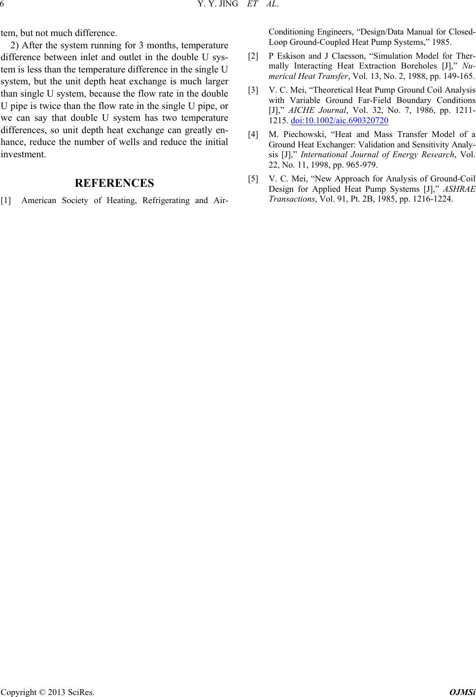 Y. Y. JING ET AL. Copyright © 2013 SciRes. OJMSi 6 tem, but not much difference. 2) After the system running for 3 months, temperature difference between inlet and outlet in the double U sys- tem is less than the temperature difference in the single U system, but the unit depth heat exchange is much larger than single U system, because the flow rate in the double U pipe is twice than the flow rate in the single U pipe, or we can say that double U system has two temperature differences, so unit depth heat exchange can greatly en- hance, reduce the number of wells and reduce the initial investment. REFERENCES [1] American Society of Heating, Refrigerating and Air- Conditioning Engineers, “Design/Data Manual for Closed- Loop Ground-Coupled Heat Pump Systems,” 1985. [2] P Eskison and J Claesson, “Simulation Model for Ther- mally Interacting Heat Extraction Boreholes [J],” Nu- merical Heat Transfer, Vol. 13, No. 2, 1988, pp. 149-165. [3] V. C. Mei, “Theoretical Heat Pump Ground Coil Analysis with Variable Ground Far-Field Boundary Conditions [J],” AICHE Journal, Vol. 32, No. 7, 1986, pp. 1211- 1215. doi:10.1002/aic.690320720 [4] M. Piechowski, “Heat and Mass Transfer Model of a Ground Heat Exchanger: Validation and Se nsitivity Analy - sis [J],” International Journal of Energy Research, Vol. 22, No. 11, 1998, pp. 965-979. [5] V. C. Mei, “New Approach for Analysis of Ground-Coil Design for Applied Heat Pump Systems [J],” ASHRAE Transactions, Vol. 91, Pt. 2B, 1985, pp. 1216-1224. |