Paper Menu >>
Journal Menu >>
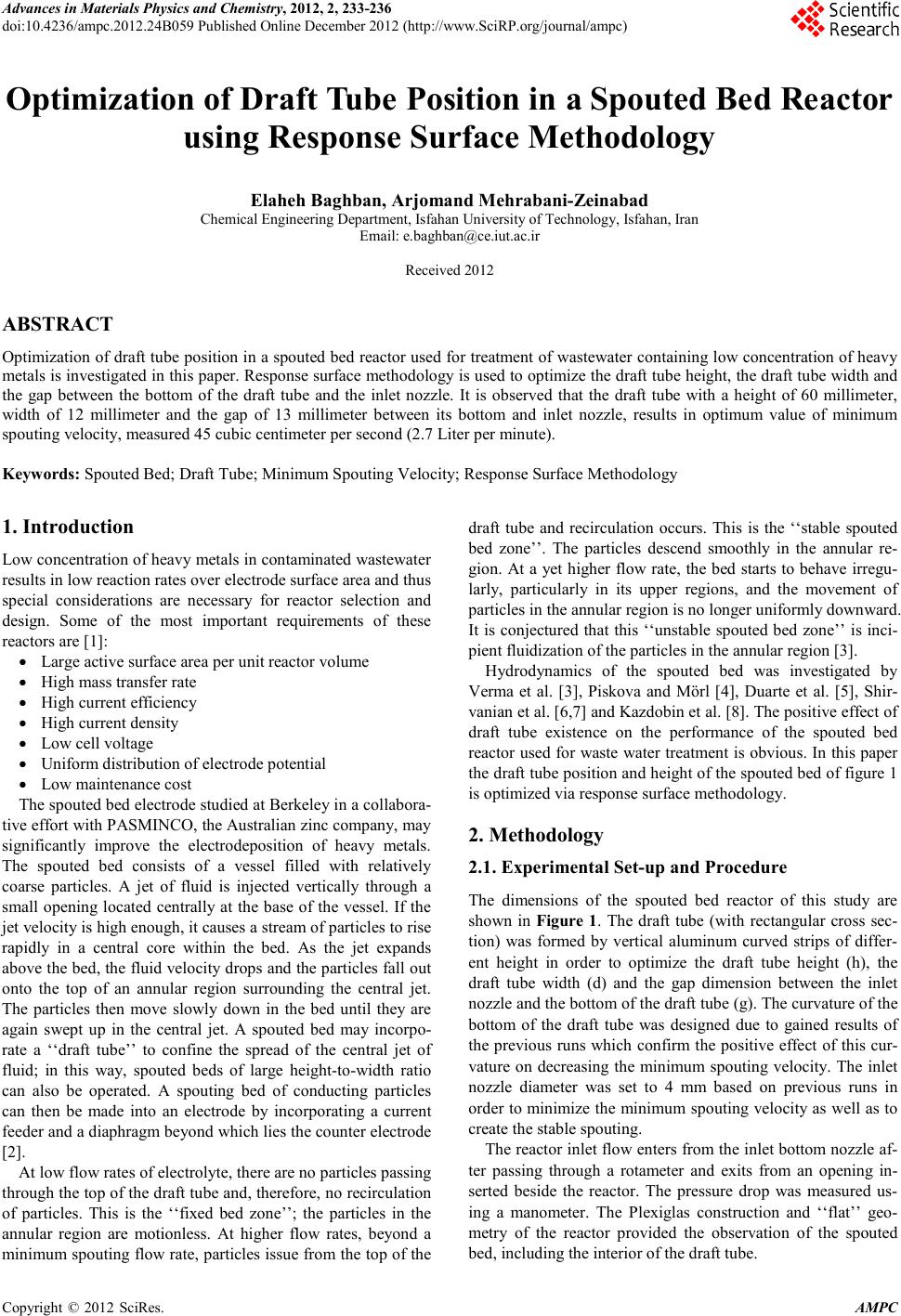 Advances in Ma terials Physics and Che mist ry, 2012, 2, 233-236 doi:10.4236/ampc.2012.24B059 Published Online December 2012 (htt p://www.SciRP.org/journal/ampc) Copyright © 2012 SciRes. AMPC Optimization of Draft Tube Position in a Spouted Bed Reactor using Re s ponse Surface Me t hod ology Elaheh Baghban, A r jomand Mehrabani-Zeinabad Ch emical Engineering D epartmen t, Isfahan University of Technology, Isfahan, Iran Email: e.baghban@ce.iut.ac.ir Received 2012 ABSTRACT Optimization of draft tube position in a spouted bed reactor used for treatment of wastewater containing low concentration of heavy metals is investigated in this paper. Response surface methodology is used to optimize the draft tube height, the draft tube width and the gap between the bottom of the draft tube and the inlet nozzle. It is observed that the draft tube with a height of 60 millimeter, width of 12 millimeter and the gap of 13 millimeter between its bottom and inlet nozzle, results in optimum value of minimum spouting velocity, measured 45 cubic centimeter per second (2.7 Liter per minute). Keywords: Spouted Be d; Draft Tube; Minimum Spouting Velocity; Response Surface Methodology 1. Introduction Low concentration of heavy metals in contaminated wastewater result s in lo w reaction r ates over electro de surface area an d thus special considerations are necessary for reactor selection and design. Some of the most important requirements of these reactors are [1]: • Large active surface area per unit reactor volume • High mass transfer rate • High curr ent efficiency • Hig h cur rent densit y • Low cell voltage • Uniform distr i bution of ele c t rode potent ia l • Low maintenance cos t The spouted bed electrode studied at Berkeley in a collabora- tive effort with PASMINCO, the Australian zinc company, may significantly improve the electrodeposition of heavy metals. The spouted bed consists of a vessel filled with relatively coarse particles. A jet of fluid is injected vertically through a small opening located centrally at the base of the vessel. If the jet veloci ty is hi gh enough , it causes a stream of part icles to rise rapidly in a central core within the bed. As the jet expands above the bed, the fluid velocity drops and the particles fall out onto the top of an annular region surrounding the central jet. The particles then move slowly down in the bed until they are again swept up in the central jet. A spouted bed may incorpo- rate a ‘‘draft tube’’ to confine the spread of the central jet of fluid; in this way, spouted beds of large height-to-width ratio can also be operated. A spouting bed of conducting particles can then be made into an electrode by incorporating a current feeder and a diaphragm beyond which lies the counter electrode [2]. At low flo w rates of electrol yt e, there ar e no p articles passing through the top of the draft tube and, therefore, no recirculation of particles. This is the ‘‘fixed bed zone’’; the particles in the annular region are motionless. At higher flow rates, beyond a minimum spouting flow rate, p articles issue fro m th e top of the draft tube and recirculation occurs. This is the ‘‘stable spouted bed zone’’. The particles descend smoothly in the annular re- gion. At a yet higher flow rate, the bed starts to behave irregu- larly, particularly in its upper regions, and the movement of particles in the annular region is no longer uniformly downward. It is conjectured that this ‘‘unstable spouted bed zone’’ is inci- pient fluidization of the particles in the annular region [3]. Hydrodynamics of the spouted bed was investigated by Verma et al. [3], Piskova and Mörl [4], Duarte et al. [5], Shir- vanian et al. [6 ,7] and Kazd obin et al. [8] . The posit ive effect o f draft tube existence on the performance of the spouted bed reactor u sed for waste water tre atment is obvious. In this paper the draft tube position and height of the spouted bed of figure 1 is optimized via response surface methodology. 2. Methodology 2.1. Experimental Set-up and P r ocedure The dimensions of the spouted bed reactor of this study are shown in Figure 1. The draft tube (with rectangular cross sec- tion) was formed by vertical aluminum curved strips of differ- ent height in order to optimize the draft tube height (h), the draft tube width (d) and the gap dimension between the inlet nozzl e and the bottom of the draft tube (g). The curvature of the bottom of the draft tube was designed due to gained results of the previous runs which confirm the positive effect of this cur- vature on decreasing the minimum spouting velocity. The inlet nozzle diameter was set to 4 mm based on previous runs in order to minimize the minimum spouting velocity as well as to create the s table spouting. The reactor inlet flow enters fro m th e inlet bottom no zzle af- ter passing through a rotameter and exits from an opening in- serted beside the reactor. The pressure drop was measured us- ing a manometer. The Plexiglas construction and ‘‘flat’’ geo- metry of the reactor provided the observation of the spouted bed, including the interior of the draft tube. 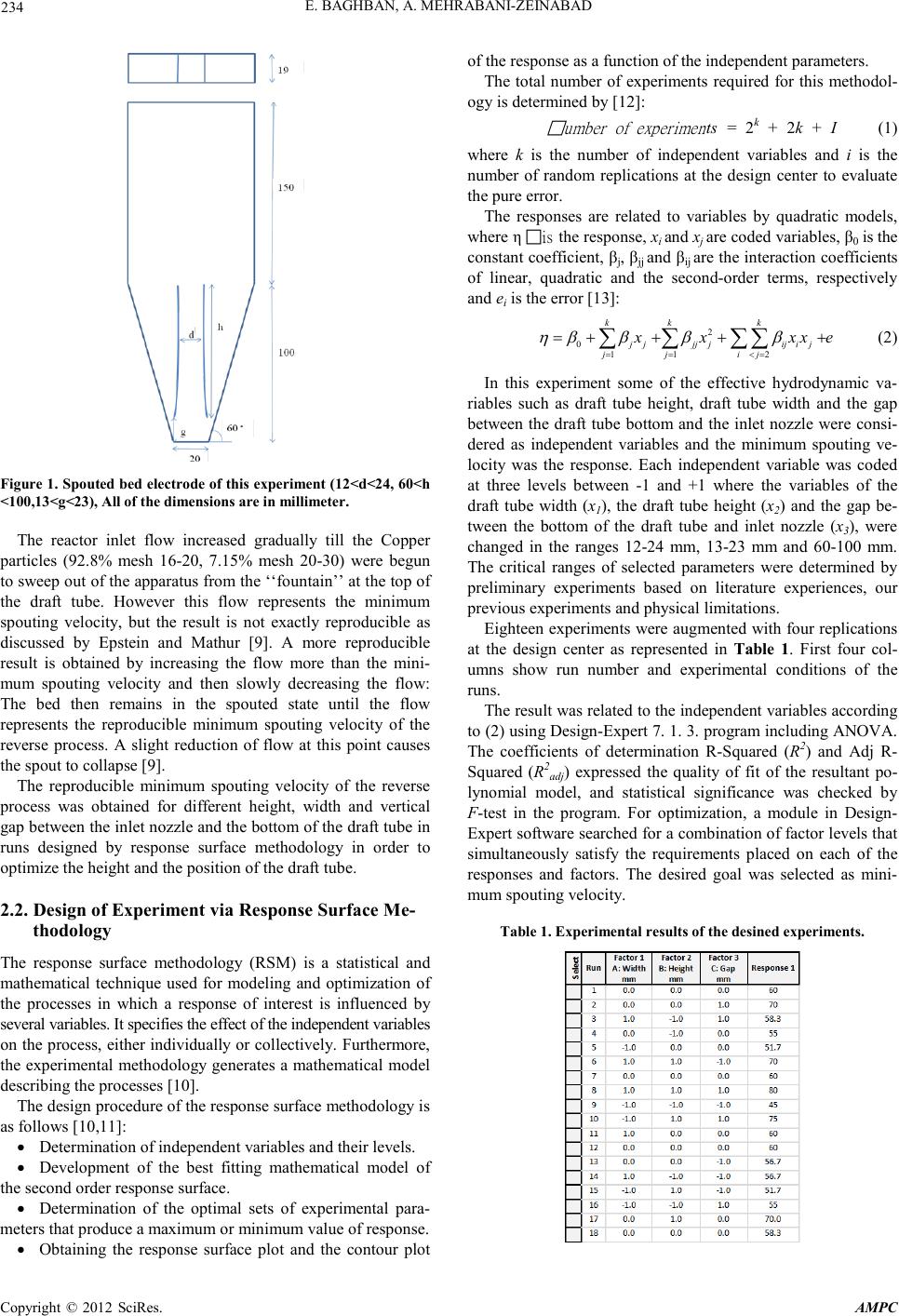 E. BAGH BAN , A. MEH R AB ANI-Z EIN ABAD Copyright © 2012 SciRes. AMPC 234 Figure 1. Spouted bed electrode of this experiment (12<d<24, 60<h <100,13<g<23), All of the dimensions are in millimeter. The reactor inlet flow increased gradually till the Copper particles (92.8% mesh 16-20, 7.15% mesh 20-30) were begun to sweep out of the apparatus from the ‘‘fountain’’ at the top of the draft tube. However this flow represents the minimum spouting velocity, but the result is not exactly reproducible as discussed by Epstein and Mathur [9]. A more reproducible result is obtained by increasing the flow more than the mini- mum spouting velocity and then slowly decreasing the flow: The bed then remains in the spouted state until the flow represents the reproducible minimum spouting velocity of the reverse process. A slight reduction of flow at this point causes the spout to collapse [9]. The reproducible minimum spouting velocity of the reverse process was obtained for different height, width and vertical gap between the inlet nozzle and the bottom of the draft tube in runs designed by response surface methodology in order to optimize the height and the position of the draft tube. 2.2. Design of Experiment via Response Surface Me- thodology The response surface methodology (RSM) is a statistical and mathematical technique used for modeling and optimization of the processes in which a response of interest is influenced by several variables. It specifies the effect of the independent variables on the process, either individually or collectively. Furthermore, the experimental method ology generates a mathematical model describing the processes [10]. The design procedure of the response surface methodology is as follows [10,11]: • Determinat ion of in depend ent variables and thei r levels. • Development of the best fitting mathematical model of the seco nd order res ponse surface. • Determination of the optimal sets of experimental para- meters th at produce a maximum o r minimum value of response. • Obtaining the response surface plot and the contour plot of the response as a function of the independ ent parameters. The total number of experiments required for this methodol- ogy is determined by [12]: umber of experimen ts = 2k + 2k + I (1) where k is the number of independent variables and i is the number of random replications at the design center to evaluate the pure error. The responses are related to variables by quadratic models, where η is the response, xi and xj are coded variables, β0 is the constant coefficient, βj, βjj and βij are t he interact ion coefficients of linear, quadratic and the second-order terms, respectively and ei is the error [13]: 2 011 2 kk k j jjj jiji j j jij xxxx e ηβ βββ = =<= =+++ + ∑ ∑∑∑ (2) In this experiment some of the effective hydrodynamic va- riables such as draft tube height, draft tube width and the gap between the draft tube bottom and the inlet nozzle were consi- dered as independent variables and the minimum spouting ve- locity was the response. Each independent variable was coded at three levels between -1 and +1 where the variables of the draft tube width (x1), the draft tube height (x2) and the gap be- tween the bottom of the draft tube and inlet nozzle (x3), were changed in the ranges 12-24 mm, 13-23 mm and 60-100 mm. The critical ranges of selected parameters were determined by preliminary experiments based on literature experiences, our previous experiments and physical limitations. Eighteen experiments were augmented with four repli cations at the design center as represented in Table 1. First four col- umns show run number and experimental conditions of the runs. The result was related to th e independ ent variabl es accord ing to (2) using Design-Expert 7. 1. 3. program including ANOVA. The coefficients of determination R-Squared (R2) and Adj R- Squ ared (R2adj) expressed the quality of fit of the resultant po- lynomial model, and statistical significance was checked by F-test in the program. For optimization, a module in Design - Expert so ftware searched for a combination of factor levels that simultaneously satisfy the requirements placed on each of the responses and factors. The desired goal was selected as mini- mum spouting velocity. Tabl e 1. Experimental results of the desined experiments. 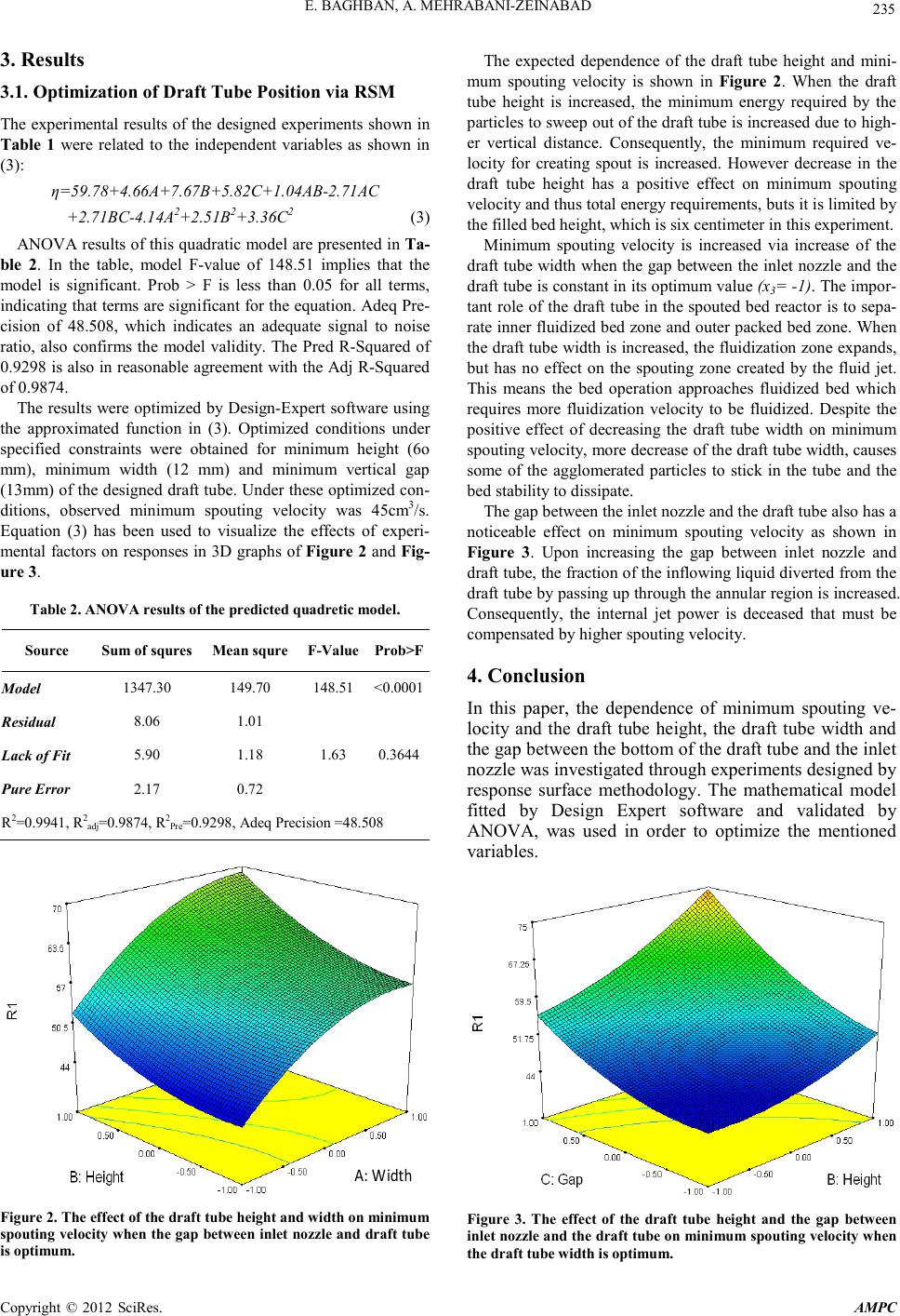 E. BAGH BAN , A. MEHRABANI-Z EIN ABAD Copyright © 2012 SciRes. AMPC 235 3. Results 3.1. Optimization of Draft Tube Position via RSM The experi mental result s of the design ed experiments sh own in Table 1 were related to the independent variables as shown in (3): η=59.78+4.66A+7.67B+5.82C+1.04AB-2.71AC +2.71BC-4.14A2+2.51B2+3. 36C2 (3) ANOVA results of this quadratic model are presented in Ta- ble 2. In the table, model F-value of 148.51 implies that the model is significant. Prob > F is less than 0.05 for all terms, indicating that terms are significant for the equation. Adeq Pre- cision of 48.508, which indicates an adequate signal to noise ratio, also confirms the model validity. The Pred R-Squared of 0.9298 is also in reasonable agreement with the Adj R-Squared of 0.9874. The result s were op timized by Design-Expert soft ware using the approximated function in (3). Optimized conditions under specified constraints were obtained for minimum height (6o mm), minimum width (12 mm) and minimum vertical gap (13mm) of the designed draft tube. Under these optimized con- ditions, observed minimum spouting velocity was 45cm3/s. Equation (3) has been used to visualize the effects of experi- mental factors on responses in 3D graphs of Figure 2 and Fig- ure 3. Tabl e 2. ANOVA results of the predicted quadretic model. Source Sum of squres Mea n s qure F-Value Prob>F Model 1347.30 149.70 148.51 <0.0001 Residual 8.06 1.01 Lack of F i t 5.90 1.18 1.63 0.3644 Pure Error 2.17 0.72 R2=0.9941, R2adj=0.9874, R2Pr e =0.9298, Adeq Precision =48.508 A: Width Figure 2. The eff ect of t he draft tube height and width on minimum spouting veloci ty when the gap between inlet nozzle and draft tube is optimum. The expected dependence of the draft tube height and mini- mum spouting velocity is shown in Figure 2. When the draft tube height is increased, the minimum energy required by the particles t o sweep out of the draft tube is in creased due to high- er vertical distance. Consequently, the minimum required ve- locity for creating spout is increased. However decrease in the draft tube height has a positive effect on minimum spouting velocity and thus total energy requirements, buts it is limited by the filled bed height, which is six centimeter in this experiment. Minimum spouting velocity is increased via increase of the draft tube width when the gap between the i nlet nozzle and the draft tube is constant in its optimum value (x3= -1). The impor- tant role of the draft tube in the spouted bed reactor is to sepa- rate inner fluidized bed zone and outer packed bed zone. When the d raft tube width i s increased, the fluidization zone expands, but has no effect on the spouting zone created by the fluid jet. This means the bed operation approaches fluidized bed which requires more fluidization velocity to be fluidized. Despite the positive effect of decreasing the draft tube width on minimum spouting velocity, more decrease of the draft tube width, causes some of the agglomerated particles to stick in the tube and the bed stability to dissipate. The gap between the inlet nozzl e and the draft tube als o has a not iceable effect on minimum spouting velocity as shown in Figure 3. Upon increasing the gap between inlet nozzle and draft tube, the fraction of the inflowing liquid diverted from the draft tube by passing up through the annular region is increased. Consequently, the internal jet power is deceased that must be compensated by higher spouting velocity. 4. Conclusion In this paper, the dependence of minimum spouting ve- locity and the draft tube height, the draft tube width and the gap between the bottom of the draft tube and t he i nle t nozz le wa s in ves ti ga ted t hro u gh exp e ri ments desi gne d b y response surface methodology. The mathematical model fitted by Design Expert software and validated by ANOVA, was used in order to optimize the mentioned variables. Figure 3. The effect of the draft tube height and the gap between inlet nozzl e and the draft tube on minimum spouting velocity when the draft tube width is optimum. 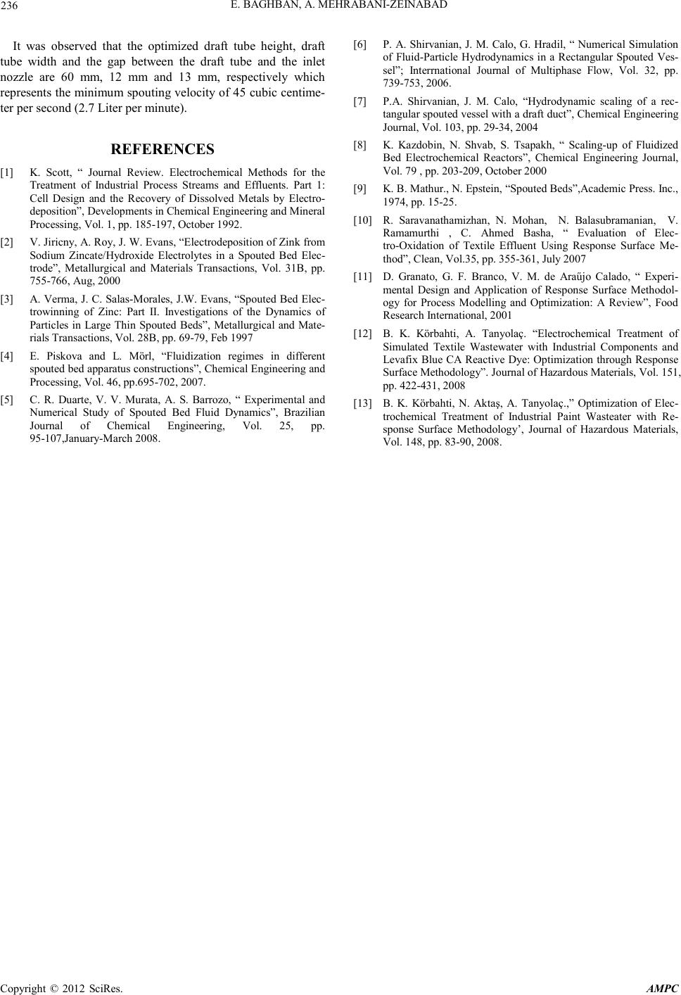 E. BAGH BAN , A. MEH R AB ANI-Z EIN ABAD Copyright © 2012 SciRes. AMPC 236 It was observed that the optimized draft tube height, draft tube width and the gap between the draft tube and the inlet nozzle are 60 mm, 12 mm and 13 mm, respectively which represents the minimum spouting velocity of 45 cubic centime- ter per second (2.7 Liter p er min ut e). REFERENCES [1] K. Scott, “ Journal Review. Electrochemical Methods for the Treatment of Industrial Process Streams and Effluents. Part 1: Cell Design and the Recovery of Dissolved Metals by Electro- deposition”, Developments in Chemical Engineering and Mineral Processing, Vol. 1, pp. 185-197, October 1992. [2] V. Jiricny, A. Roy, J. W. Evans, “Electrodepositi on of Zin k from Sodium Zincate/Hydroxide Electrolytes in a Spouted Bed Elec- trode”, Metallurgical and Materials Transactions, Vol. 31B, pp. 755-766, Aug, 2000 [3] A. Verma, J. C. Salas-Mora les, J.W. Evans , “Spout ed Bed Elec- trowinning of Zinc: Part II. Investigations of the Dynamics of Particles in Large Thin Spouted Beds”, Metallurgical and Mate- rials Transactions, Vol. 28B, pp . 69-79, Feb 1997 [4] E. Piskova and L. Mörl, “Fluidization regimes in different spouted bed apparatus constructions”, Chemical Engineering and Processin g, Vol. 46 , pp.695-702, 2007. [5] C. R. Duarte, V. V. Murata, A. S. Barrozo, “ Experimental and Numerical Study of Spouted Bed Fluid Dynamics”, Brazilian Journal of Chemical Engineering, Vol. 25, pp. 95-107,January-Marc h 2 008. [6] P. A. Shirvanian, J. M. Calo, G. Hradil, “ Numerical Simulation of Fluid-Particle Hydrodynamics in a Rectangular Spouted Ves- sel”; Interrnational Journal of Multiphase Flow, Vol. 32, pp. 739-753, 2006. [7] P.A. Shirvanian, J. M. Calo, “Hydrodynamic scaling of a rec- tangular spouted vessel with a draft duct”, Chemical Engineering Journ al, Vol. 103, pp. 29-34, 2004 [8] K. Kazdobin, N. Shvab, S. Tsapakh, “ Scaling-up of Fluidized Bed Electrochemical Reactors”, Chemical Engineering Journal, Vol. 79 , pp. 20 3-209, October 2000 [9] K. B. Mathur., N. Epstein, “Spouted Beds”,Academic Press. Inc., 1974, pp. 15-25. [10] R. Saravanathamizhan, N. Mohan, N. Balasubramanian, V. Ramamurthi , C. Ahmed Basha, “ Evaluation of Elec- tro-Oxidation of Textile Effluent Using Response Surface Me- thod”, Clean , Vol. 35, pp. 355-361, July 2007 [11] D. Granato, G. F. Branco, V. M. de Araűjo Calado, “ Experi- mental Design and Application of Response Surface Methodol- ogy for Process Modelling and Optimization: A Review”, Food Resear ch Internatio nal , 20 0 1 [12] B. K. Körbahti, A. Tanyolaç. “Electrochemical Treatment of Simulated Textile Wastewater with Industrial Components and Levafix B lue CA Reacti ve Dye: Opt imizati on th rough Response Surface Methodology”. Journal of Hazardous Materials, Vol. 151, pp. 422-431, 2008 [13] B. K. Körbahti, N. Aktaş, A. Tanyolaç.,” Optimization of Elec- trochemical Treatment of Industrial Paint Wasteater with Re- sponse Surface Methodology’, Journal of Hazardous Materials, Vol. 148, pp. 83-90, 2008. |