Paper Menu >>
Journal Menu >>
 Journal of Global Positioning Systems (2004) Vol. 3, No. 1-2: 154-166 Limitations of Pseudolite Systems Using Off-The-Shelf GPS Receivers Mustafa Ozgur Kanli School of Surveying and Spatial Information Systems, The University of New South Wales, Sydney, Australia e-mail: m.kanli@student.unsw.edu.au Tel: + 61-2-6229-1780; Fax: + 61-2-6229-1778 Received: 15 Nov 2004 / Accepted: 3 Feb 2005 Abstract. Pseudolites (PLs) are ground-based transmitters that transmit GPS-like signals. They have been used to test GPS system elements and to enhance GPS in certain applications by providing better accuracy, integrity and availability through the use of PL signals in addition to the GPS signals. PLs are also a promising technology for providing positioning in indoor, high multipath environments where GPS signals are generally unavailable or severely attenuated and of questionable quality. In experiments to date, researchers have almost exclusively used PLs that transmit C/A code on L1/L2 in order to use existing off-the-shelf GPS receivers. This is because no hardware modifications to the GPS receiver are necessary and only minor changes to the receiver firmware are needed to track a PL’s signal. However, there are some fundamental issues that limit the effectiveness of a PL system using C/A code on L1/L2. These include the legality of transmitting on L1/L2, cross-correlation between PL and GPS signals, saturation of GPS receiver front-ends, and the limited multipath mitigation offered by C/A codes. When combined with other problems inherent to all PL systems such as near- far, multipath, and synchronization, the issues in using L1/L2 C/A code PL systems further complicates the design and deployment of such systems and places limits on its operational effectiveness. This paper presents the issues which limit PL systems that use GPS hardware and explores the impact of these issues on some common PL applications. Key words: pseudolite, cross-correlation, jamming. 1 Introduction The concept of using ground-based GPS signal transmitters originated from the time when GPS was first being developed. These transmitters, which came to be known as Pseudolites (PLs), enabled developers to test GPS concepts before the first satellites were even launched. Since then, PLs have been found to improve geometry for accurate positioning, especially in the vertical component. They provide additional ranging signals to augment existing GPS signals, increasing availability. In some environments, such as indoors, GPS signals are heavily attenuated and are of questionable quality. In these cases, PLs have been used to provide alternative ranging signals. A comprehensive summary of PL technology, including PL designs and applications, is provided by Wang (2002). There, the reader will also find many helpful references. Almost all purpose-built PLs transmit on the L1 frequency. Some also transmit on L2, or even both. Those that are simply comprised of a signal generator may transmit on any range of frequencies. Most L1/L2 PLs typically use spreading codes from the same family as the C/A codes used in GPS satellites. This practice enables the PL to closely resemble a GPS satellite, and this is important to allow existing off-the-shelf (OTS) GPS receivers to track a PL’s signal. Only slight changes to a GPS receiver’s firmware is required to achieve this. First is a modification to the receiver’s search database, allowing it to look for local PLs as well as GPS satellites. If the PL modulates data onto its signal, software to correctly interpret this data also has to be written. Some other thresholds and assumptions may also need to be adjusted. Importantly, no hardware changes to a receiver’s correlators or front-end circuitry are needed. This practicality simplifies experimentation and leaves more time to be spent on research. Unfortunately, this convenience comes with a price. The L1 and L2 frequency bands are protected and reserved for radionavigation; legal issues hinder unlicensed transmissions in these bands. PL signals are often considerably stronger than GPS signals. This can result in jamming, which will deny GPS to other nearby receivers that don’t participate in PL navigation. Typical OTS GPS receivers may also be overwhelmed by the strength of PL  Kanli: Limitations of Pseudolite Systems Using Off-The-Shelf GPS Receivers 155 signals; they expect weak GPS signals. Saturation of the front-end can result, which will decrease accuracy, reliability and introduce other complications. For indoor PL navigation, the C/A code chipping rate used in GPS does not sufficiently limit range errors due to multipath. These factors contribute to other complications that can affect the operational effectiveness of PLs. This paper will begin with a discussion of issues inherent to all PL systems; these are near-far, multipath and synchronization. Then, issues specific to L1 C/A code PLs will be presented. A brief look at the impacts of these issues on some common applications will follow. The paper will then conclude with a section discussing the recent developments in PL technology. Other competing positioning systems will also be briefly discussed, as well as some possible future developments. 2 Issues in pseudolite systems 2.1 General Issues This section will describe the general issues confronted by PL systems. 2.1.1 Near-far GPS satellites are located in near-circular orbits around the Earth with a radius of about 26,560 km. This puts the typical distance between a user receiver and a visible satellite overheard at about 20,000 km. Changes in this distance due to typical user and satellite motion are insignificant compared to the overall separation distance. Also, the radiation patterns of GPS satellite antennas are shaped to spread the RF signal almost uniformly over the surface of the Earth. These factors ensure that a user receiver can expect to see GPS signal strengths around - 160 dBW from all visible satellites. In contrast, PLs are located much closer to user receivers so that user movements can cause significant variations in the distance between PLs and user receivers. Because of this, user receivers will see large variations in PL signal strengths. For example, for an isotropic PL antenna the signal strength 30 m away will be 24 dB stronger than the signal strength 500 m away. This is known as the near-far effect. The repercussions of the near-far effect on GPS signals are primarily jamming and limited operating distance. For instance in a standalone PL network each PL will, within an area of close proximity, jam the signals from other distant PLs. Receivers in such a network will observe varying PL signal strengths at different locations. Off- the-shelf GPS receivers expect signals from all sources to be of approximately equal strength. This will only occur at points equi-distant to all PLs. PL signals can be more than 30 dB stronger than GPS signals; which is greater than the worst case code separation (21.6 dB) between C/A codes. In an integrated GPS/PL system, PLs can thus potentially jam GPS signals at close proximity. The output power of the PL can be calibrated to minimize jamming, but this limits the operating range of the PL. The most popular solution used to mitigate the near-far problem, as presented by Klein and Parkinson (1984), is to pulse the PL signals at fixed cycle rates (typically 10%). This provides a 10 dB improvement in the signal- to-interference level. Transmitting the signals at a frequency offset from GPS L1 (while remaining within the same frequency band as GPS) and using longer sequence spreading codes have also been suggested as potential solutions. However, not all off-the-shelf GPS receivers can accommodate the use of different spreading codes and/or the frequency offsets. A different approach, proposed by Madhani et al (2001), uses successive interference cancellation, where the receiver accurately regenerates the interfering PL signal before subtracting it from the total received signal to yield a partially cleaned version of the received signal. This approach relies on the ability of the receiver to accurately track both the interfering signal and the desired weaker signal. In order to do this, the receiver requires an ADC with sufficient resolution and an RF front-end with sufficient dynamic range to accommodate both sets of signals. Most off-the- shelf GPS receivers, however, don’t have this capability. Shaping the radiation pattern of PL transmit antennas is another approach used in the mitigation of the near-far problem (Söderholm et al, 2001). This approach aims to provide a near-uniform spread of PL signal strength covering only a specific desired area, achieved by appropriate orientation of the transmit antennas of the PLs. While effective within the desired area, near-far conditions are still apparent on the fringes of, and outside, this operational area. Custom antenna designs are required to provide sufficient coverage of each environment. Thus, this approach will not be suitable for dynamic environments such as in shipping yards, where moving freight containers cause considerable changes to the landscape. Furthermore, the deployment of PLs is restricted by the very nature of this near-far mitigation technique. 2.1.2 Multipath A pseudo-range measurement involves determining the propagation time of a ranging signal along a direct line- of-sight path from its source antenna to a receiver’s antenna. Due to reflective objects in the environment, the signals at a receiver’s antenna can be composed of both direct ranging signals and any number of reflected (multipath) ranging signals. These multipath signals are  156 Journal of Global Positioning Systems delayed relative to the direct signal and have differing amplitude, phase, and polarization, characterized by the reflecting surface and the number of reflections. Pseudo- range errors of tens of metres often result from the presence of multipath signals, which in most cases is the largest error source. Multipath signals give rise to larger pseudo-range measurement errors than carrier phase measurement errors, which are of the order centimetres. Multipath signals may also destructively interfere with direct signals resulting in multipath fades. A good introduction to multipath effects is given by Braasch (1996). Unlike near-far, the problem of multipath is an issue for GPS users as well as for designers of PL systems. The severity of multipath varies with the environment in which the positioning signals are applied. As an example, when PLs are used for augmenting GPS in aircraft approach and landing, a typical source of multipath is long delay ground bounce. In this case, multipath signals are typically delayed by more than a ranging code chip period. Theoretical texts may show that the multipath signal will have no effect. However, C/A code correlation side-lobes provide a way for relatively strong long delay multipath signals to induce errors of several metres. It should be noted that a GPS receiver may choose to ignore satellites at low elevations to exclude the possibility of ground bounce signals introducing pseudo-range errors. For PL systems however, all signal sources are almost always at low elevations significantly increasing the amount of multipath. A different case is a PL system for indoor positioning, where there is a wide range of reflectors in close proximity of the receiving antenna. Examples include reinforced concrete structures, home/office furnishings and antenna mountings (man or machine). These reflectors generate a prevalence of short delay multipath, where ranging signals are delayed by less than a ranging code chip period. Short delay multipath typically has a greater impact on pseudo-ranges than long delay multipath, and it is also harder to mitigate its effects. For example, a single multipath signal with ¼ the amplitude of the direct signal can induce a 40 m range error (Misra and Enge, 2001). Multipath mitigation can be performed on several levels. First, multipath signals can be attenuated selectively at the antenna. A choke-ring antenna is one device that can achieve this (Kunysz, 2003). It consists of concentric rings of grounded metal around the antenna element. These attenuate signals that arrive from low elevations relative to the axis of the metal rings. Choke-ring antennas are effective in attenuating ground bounce multipath signals. Other directional antenna designs have been used to attenuate signals from non-line-of-sight paths (Stolk and Brown, 2003). Of course, such techniques are only useful if the multipath signals arrive from the directions they are anticipated from. Modelling multipath errors in software in order to minimize its effects is another type of mitigation. One approach includes the simulation of different types of reflectors at a variety of distances from receiver antennas. Receiver tracking algorithms can then be modelled to determine the response of the tracking loop to the reflected signals (Weiss et al, 2003). Modelling multipath or multipath estimation may be effective for controlled, static environments but it is unsuitable for dynamic, indoor and high multipath environments. In such cases, receivers moving through a reflective environment will encounter multipath effects that deviate from the model. Multipath mitigation is also performed at the level of the receiver’s correlators. Ordinary receivers perform correlation with a pair of early and late tracking arms separated by a chip period. These tracking arms straddle the correlation peak by maintaining the level difference between the pair at zero. In the presence of a multipath signal, however, keeping the level difference at zero may not imply that the tracking arms straddle the true correlation peak. Decreasing the separation between the tracking arms is one way to achieve a better result in the presence of medium delay multipath signals. The Narrow CorrelatorTM operates in this fashion (Van Dierendonck et al, 1992). Other correlation techniques such as the Double Delta correlator, the Early/Late Slope technique and the Early1/Early2 tracker have also been devised. These can dramatically decrease the maximum pseudo- range error due to multipath. Irsigler and Eissfeller (2003) present a good comparison of the multipath mitigation of different correlation techniques mentioned here. It is important to note that techniques like the Narrow CorrelatorTM require a receiver with a front-end having a wide bandwidth relative to the chipping rate of the ranging code used. For C/A code, typical narrow correlator receivers have pre-correlator bandwidths of 16 MHz. The consequence of having such a wide bandwidth is that signals from adjacent radio bands are more likely to cause interference. Also, not all OTS GPS receivers employ such advanced multipath mitigation techniques. 2.1.3 Pseudolite synchronization Fundamental to the operation of GPS is satellite clock predictability. Without precisely synchronized satellite clocks, precise time transfer and accurate stand-alone navigation would be impossible. The cesium and rubidium atomic clocks onboard GPS satellites have stabilities of the order of 1 part in 1013. To keep the clocks synchronized, the GPS Operational Control Segment (OCS) uploads satellite clock corrections to the satellites at least once a day. These corrections, which are  Kanli: Limitations of Pseudolite Systems Using Off-The-Shelf GPS Receivers 157 part of the navigation message, are used by receivers to correct for the satellite clock drifts. While atomic clocks have been used in certain PL applications where a ranging signal of high quality is desired (Soon et al, 2003), most PLs typically use inexpensive temperature compensated crystal oscillators (TCXOs) to provide their reference frequency. Typical TCXOs have a stability of around 1 part in 106, more than six orders of magnitude worse than atomic standards. Because of such insufficient stability in their reference frequencies, PLs that operate asynchronously cannot provide accurate stand-alone navigation. In such cases double-differencing with a reference receiver is commonly used to eliminate PL and receiver clock biases. For a real-time solution this requires a wireless data link between the user and reference receivers. This adds operational constraints and affects performance, depending on data link range, integrity and latency. Furthermore the reference receiver must have visibility of all PLs for accurate measurements. This may mean having several reference receivers, for instance, in an indoor PL network that spans several rooms. This of course will add cost and complexity to the system. Also, timing information is eliminated in the double- differencing procedure. So, asynchronous PL operation will be unsuitable for those applications in which precise time transfer is important. Asynchronous operation of PLs can also complicate the pulsing technique often used for the mitigation of the near-far effect. Consider the case of two PLs that are both pulsed with a duty cycle of 10% over the C/A code duration. If the PL pulsing scheme is asynchronous, the transmission cycles of both PLs may overlap for durations that vary according to the drift of both PL clocks. This will impact on how well a receiver tracks both PL signals. Since a receiver can only correlate for 10% of either PL’s transmission, overlapping of the two signals can cause a significant increase in interference, especially in a saturated receiver. In the worst case both PLs will be mutually jamming each other. An example of asynchronous PLs that are used to augment GPS for an aircraft precision approach and landing is given by Soon et al (2003). Kee et al (2000) present a successful account of indoor positioning using only asynchronous PLs. Cobb (1997) discusses a synchronous pseudolite, known as a synchrolite. A synchrolite acts as an electronic mirror to reflect GPS satellite signals from a known point on the ground. A synchrolite consists of a co-located GPS receiver and a PL transmitter. The receiver is able to determine the precise code phase and carrier frequency of the satellite signal that it is tracking. This information is then used to generate the PL transmissions that are synchronous to the GPS signals. Synchrolite signal measurements are typically differenced from satellite signal measurements to eliminate spatially correlated errors. Söderholm and Jokitalo (2002) present a synchronous PL network for indoor positioning. The PLs in this network are synchronized by a Master Control Station (MCS) that tracks all PL signals using a reference receiver. Clock corrections are communicated to all the PLs via hard wired links. This centralized approach to synchronization that mirrors the GPS OCS has several disadvantages. First, the reference receiver must have visibility of all PLs in the network. In the OCS this is achieved by distributing monitoring stations around the world. Similarly, the MCS needs to collect measurements from as many reference receivers as are required to track all PLs in the network. Second, the synchronization control loop of the MCS must operate much more frequently than its counterpart, the OCS. This is because PL clocks are much less stable than the atomic standards used in GPS satellites. Obviously, adding more PLs to the network would also mean more computations for the MCS, and this reduces the scalability of the system. Although hard wired data links were presented, these could be substituted by wireless links to eliminate the process of laying communication cable during installation. However, running such a high frequency synchronization control loop over communication links to remote PLs will undoubtedly add noise due to communication latency. A decentralized approach to synchronization has been demonstrated by Kee et al (2003) and Barnes et al (2003). In a decentralized system, each PL has a co-located receiver that tracks its own signal as well as a reference signal. The reference signal may be the transmission of a PL selected to be “master”, or that of a GPS satellite. PL clock corrections can then be determined by taking single-difference measurements of pseudo-range and Integrated Carrier Phase (ICP) between the reference signal and the local PL signal. Because the receiver is co- located, control loop latencies are minimized and the PL network is highly scalable; any new PLs can be added to the network without being limited by data links or being concerned about the visibility of PLs to a reference receiver. Having a co-located receiver, however, also adds to the cost and complexity of PLs. In a decentralized system, various synchronization topologies can be formed to suit the application. For instance PLs are not required to track the “master” PL to be synchronous to the network. A PL can be selected to synchronize to another PL that is already synchronous to the master PL. This propagation of time (i.e. PL synchronization) has been demonstrated by Barnes et al (2003). Clearly, propagation of PL synchronization allows for easy expansion of PL networks. Consider an indoor PL network for a warehouse that requires expansion to cover outdoor adjacent delivery sites. Additional PLs can be placed outside that only need to 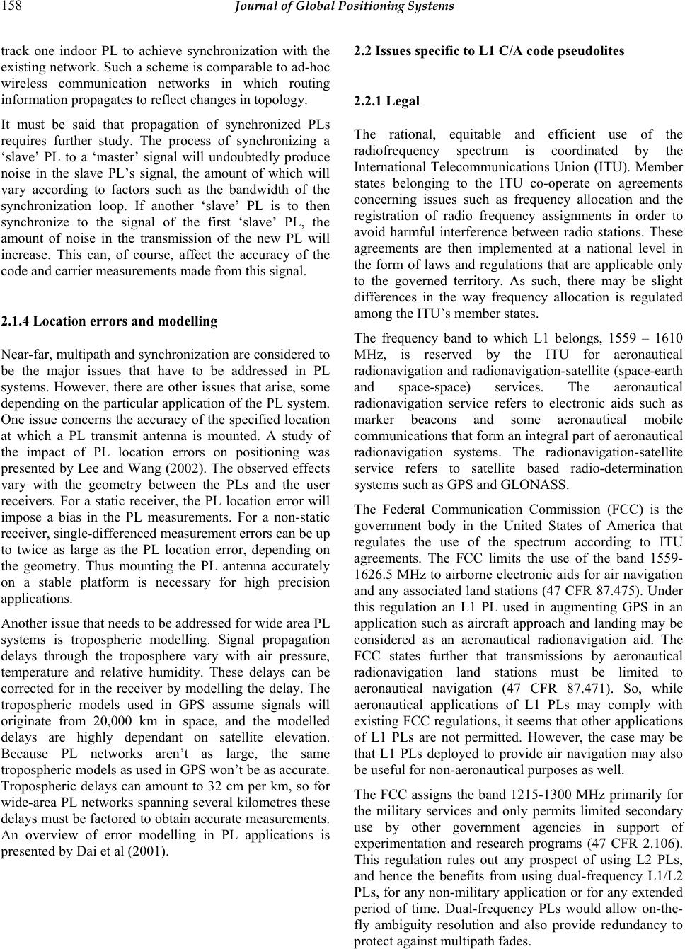 158 Journal of Global Positioning Systems track one indoor PL to achieve synchronization with the existing network. Such a scheme is comparable to ad-hoc wireless communication networks in which routing information propagates to reflect changes in topology. It must be said that propagation of synchronized PLs requires further study. The process of synchronizing a ‘slave’ PL to a ‘master’ signal will undoubtedly produce noise in the slave PL’s signal, the amount of which will vary according to factors such as the bandwidth of the synchronization loop. If another ‘slave’ PL is to then synchronize to the signal of the first ‘slave’ PL, the amount of noise in the transmission of the new PL will increase. This can, of course, affect the accuracy of the code and carrier measurements made from this signal. 2.1.4 Location errors and modelling Near-far, multipath and synchronization are considered to be the major issues that have to be addressed in PL systems. However, there are other issues that arise, some depending on the particular application of the PL system. One issue concerns the accuracy of the specified location at which a PL transmit antenna is mounted. A study of the impact of PL location errors on positioning was presented by Lee and Wang (2002). The observed effects vary with the geometry between the PLs and the user receivers. For a static receiver, the PL location error will impose a bias in the PL measurements. For a non-static receiver, single-differenced measurement errors can be up to twice as large as the PL location error, depending on the geometry. Thus mounting the PL antenna accurately on a stable platform is necessary for high precision applications. Another issue that needs to be addressed for wide area PL systems is tropospheric modelling. Signal propagation delays through the troposphere vary with air pressure, temperature and relative humidity. These delays can be corrected for in the receiver by modelling the delay. The tropospheric models used in GPS assume signals will originate from 20,000 km in space, and the modelled delays are highly dependant on satellite elevation. Because PL networks aren’t as large, the same tropospheric models as used in GPS won’t be as accurate. Tropospheric delays can amount to 32 cm per km, so for wide-area PL networks spanning several kilometres these delays must be factored to obtain accurate measurements. An overview of error modelling in PL applications is presented by Dai et al (2001). 2.2 Issues specific to L1 C/A code pseudolites 2.2.1 Legal The rational, equitable and efficient use of the radiofrequency spectrum is coordinated by the International Telecommunications Union (ITU). Member states belonging to the ITU co-operate on agreements concerning issues such as frequency allocation and the registration of radio frequency assignments in order to avoid harmful interference between radio stations. These agreements are then implemented at a national level in the form of laws and regulations that are applicable only to the governed territory. As such, there may be slight differences in the way frequency allocation is regulated among the ITU’s member states. The frequency band to which L1 belongs, 1559 – 1610 MHz, is reserved by the ITU for aeronautical radionavigation and radionavigation-satellite (space-earth and space-space) services. The aeronautical radionavigation service refers to electronic aids such as marker beacons and some aeronautical mobile communications that form an integral part of aeronautical radionavigation systems. The radionavigation-satellite service refers to satellite based radio-determination systems such as GPS and GLONASS. The Federal Communication Commission (FCC) is the government body in the United States of America that regulates the use of the spectrum according to ITU agreements. The FCC limits the use of the band 1559- 1626.5 MHz to airborne electronic aids for air navigation and any associated land stations (47 CFR 87.475). Under this regulation an L1 PL used in augmenting GPS in an application such as aircraft approach and landing may be considered as an aeronautical radionavigation aid. The FCC states further that transmissions by aeronautical radionavigation land stations must be limited to aeronautical navigation (47 CFR 87.471). So, while aeronautical applications of L1 PLs may comply with existing FCC regulations, it seems that other applications of L1 PLs are not permitted. However, the case may be that L1 PLs deployed to provide air navigation may also be useful for non-aeronautical purposes as well. The FCC assigns the band 1215-1300 MHz primarily for the military services and only permits limited secondary use by other government agencies in support of experimentation and research programs (47 CFR 2.106). This regulation rules out any prospect of using L2 PLs, and hence the benefits from using dual-frequency L1/L2 PLs, for any non-military application or for any extended period of time. Dual-frequency PLs would allow on-the- fly ambiguity resolution and also provide redundancy to protect against multipath fades.  Kanli: Limitations of Pseudolite Systems Using Off-The-Shelf GPS Receivers 159 For researchers, however, FCC regulations permit experimental radio service licences. Such a licence may allow researchers to use any government or non- government frequency, as designated by the FCC, provided that the need for the frequency requested is fully justified by the applicant (47 CFR 5). Licences are valid for either 2 or 5 years with renewals awarded only upon an adequate showing of need. It must be said that the FCC will only permit an Experimental Radio Service licence on the condition that harmful interference will not be caused to any station operating in the frequency bands allocated. The Australian Communications Authority (ACA) implements regulations based on ITU agreements in Australia. As per the ITU allocation, the frequency band 1559 – 1610 MHz in Australia is also reserved for aeronautical and radionavigation-satellite services. However, with regards to all frequency bands, section 10(1) of the Australian Radiofrequency Spectrum plan states that: ‘A frequency band may be used for an unspecified service if the unspecified service uses the frequency band to support a specified service’. Hence it seems that L1/L2 PLs may be legally used to augment GPS under existing laws. However, the use of L1/L2 PLs in any such augmentation must not cause harmful interference to the GPS service (section 10(5)). There is no clarification on whether L1/L2 PLs can be used for other purposes; however, the ACA also provides experimental radio service licences for research purposes with conditions similar to those imposed by the FCC. A recent piece of legislation announced by the ACA concerns the possession of radionavigation-satellite service (RNSS) jamming devices (ACA, 2004). While the operation of RNSS jamming devices was already prohibited, this new legislation allows for the prosecution of a person who supplies a RNSS jamming device or possesses a RNSS jamming device for the purpose of supply. The ACA defines a RNSS jamming device as “a device that is designed to have an adverse effect on the reception by RNSS receivers of RNSS radiocommunications”. While L1/L2 PLs aren’t explicitly designed for this purpose, they can easily be used to prevent the reception of GPS signals. For instance the popular IN200D PL by IntegriNautics, which has a peak output power of +6 dBm, can jam GPS signals at distances of up to 10 km. Even an L1-only PL can inhibit the reception of L2 signals by jamming satellite C/A codes on L1. This can happen because dual-frequency receivers use the shorter C/A codes to acquire the week- long P codes on L2. With such possibilities in mind, an inquiry was put forward to the ACA as to whether L1/L2 PLs would be classified as RNSS jamming devices. If so, this would certainly be of considerable concern to researchers using/developing L1/L2 PL technology in Australia. However, no reply was received by the time of writing this paper. From a rather brief look at radiofrequency spectrum regulation in the USA and Australia, it is clear that current legislation does not permit the widespread use of L1 or L2 PLs. Commercially developed PLs often have sections in their documentation that highlight this legal issue. For instance the quick-start application note for the IN200D by IntegriNautics states that users must check the local laws and acquire any necessary licences and that the licences be posted in public view during use. The author is also aware of PL experiments performed for Air Services Australia (ASA) during which a Notice to Airmen (NOTAM) was issued to warn of possible local- area interference to GPS signals. Such precautionary measures are considered important by governing authorities, even if interference to GPS signals may be minimal. The legal issues involved in using L1/L2 PLs are rarely discussed in PL research papers; the most comprehensive overview found by the author is presented by Cobb (1997). 2.2.2 Jamming GPS GPS satellite signals must compete with each other and with any other signals present in the L1/L2 frequency bands. When competing amongst other satellite signals, the auto-correlation properties of C/A codes allow a GPS receiver to differentiate between the signals of the satellites that are in view. C/A code cross-correlation averages to about -30 dB when considering all Doppler and time offsets; so there is about 30 dB of separation between the satellite signals (the worst case cross- correlation happens to be -21.6 dB). It was stated earlier that GPS signals have a typical strength of -160 dBW at the surface of the Earth. In contrast, the power level of thermal noise at the antenna of a GPS receiver is -205 dBW/Hz, which is -142 dBW for the C/A code bandwidth of 2.046 MHz. The noise figure of the amplifier immediately following the antenna must also be considered. For typical OTS GPS receivers this will increase the thermal noise to about -138 dB. This means that GPS satellite signals are about 22 dB lower than the noise floor. Since C/A codes are 1023 chips long, a GPS receiver can achieve a processing gain of about 30 dB if it integrates over a single C/A code period (1ms). Typical OTS GPS receivers can integrate for up to 20ms which corresponds to a processing gain of 43 dB. This processing gain allows the GPS receiver to raise the satellite signals up above the noise floor. The result is a post-correlation signal to noise ratio (SNR) of about 21 dB. In the ideal case, where there are no other signals present in the L1 band, GPS receivers won’t have any problem acquiring or tracking unobstructed satellite signals. Typical signal tracking loops of OTS GPS receivers can acquire and track signals with a post-correlation strength  160 Journal of Global Positioning Systems of 6 dB above the noise floor. This leaves a margin of about 15 dB. As satellite signal strengths vary due to factors such as satellite elevation and signal obstruction, a receiver will still be able to track the signals provided the theoretical 15 dB margin is not exceeded. Forssell and Olsen (2003) performed a study on the susceptibility of commercial GPS receivers to various jamming signals. Modulated and unmodulated continuous carrier waves as well as band-limited white noise centred on the L1 frequency were subjected to three different types of receivers. It was found that for the OTS receiver used, GPS signals were unable to be tracked in the presence of modulated interfering signals that were 36 dB stronger than the GPS signals. White noise required being about 53 dB stronger than GPS signals to have the same effect. The study, however, did not look at spread spectrum modulated interference signals, such as from a PL. Although PL signals can be considered noise-like, PL transmissions are modulated with C/A codes and as a result cross-correlation effects with GPS signals will become significant. Because of this PL signals are likely to interfere at power levels much less than that of white noise as reported by Forssell and Olsen. Protection from interference to GPS signals can be implemented at different levels. One level is at the receiver’s antenna. A temporal (also spectral or notch) filter at the antenna can provide some protection against continuous wave CW interference, though such a filter may be overwhelmed by interference from multiple sources/jammers. With an antenna that has multiple elements, interfering signals can be attenuated by adjusting a weight applied to the outputs of each element. Some techniques that use this approach are cancellation, spatial temporal adaptive processing (STAP) and spatial frequency adaptive processing (SFAP). Cancellation has limited use, and although STAP and SFAP both can provide 25-40 dB of jamming suppression, they do require significant computation as well as high RF dynamic range. Furthermore, the issue of phase perturbations also has to be resolved. Interference can also be suppressed internally within the receiver. Narrow-width correlators, for example, provide better immunity to interference than ordinary correlators. This was shown in the experiments performed by Forssell and Olsen (2003). A more simple yet effective method is to increase the integration time. A typical OTS receiver is limited to integrating for up to 20ms due to the presence of the 50Hz navigation data bits, which cause 180 degree phase shifts of the carrier. This limit may be overcome by data wipe-off, or by using non-coherent integration. Data wipe-off presumes prior knowledge of data bit values from an external source, for which a data link is required in real-time receivers. Non-coherent integration, meanwhile, can lead to squaring loss and thus an increase in noise. Nevertheless, although increased integration times are achievable, it is done so at the expense of the rate of measurement and navigation solution computation. A better alternative in interference cancellation involves coupling inertial navigation sensors (INS) with the receiver tracking internals at varying degrees. The most benefit is gained from tightly-coupled schemes, though with this approach comes added cost and complexity. Further details of interference cancellation techniques mentioned here are presented by Rounds (2004a and 2004b). Although a variety of interference suppression techniques are available, they are often limited to military or survey- grade GPS receivers, which are generally quite expensive. Typical OTS GPS receivers do not provide sufficient immunity against interference to be of any practical use with PL systems. To overcome this limitation PL output can be set to a low enough power level that avoids interference, though this can be a major operational restriction depending on the type of application. Another technique for minimizing interference is to pulse the PL signals. Pulsing at low duty cycles, which is often used to mitigate near-far effects, allows PL signals to be stronger than GPS signals without denying GPS to non-participating receivers. To illustrate, consider a PL pulsing at a 10% duty cycle over the C/A code period. This means that it is on for 100µs and off for 900µs. In this pulsing scheme, over a C/A code period the GPS signals’ duration is 10 times longer than that of the PL signal. This corresponds to a 10 dB difference in favour of the GPS signals. So, if a PL signal whose power is 10 dB greater than GPS signals is pulsed, to a GPS receiver the pulsed signal will appear to have the same power level as the GPS signals. In this case no interference will be caused, since the PL signal power is averaged over the 1ms integration period. For stronger PL signals, though, there will be interference effects. A receiver tracking GPS signals will correlate over only the GPS signals for 90% of the time. However, for the 10% during which the PL is transmitting, the receiver will also correlate over the PL’s in-band transmissions. If the PL signal is significantly stronger than the GPS signal, a reduced correlation gain in the GPS signal will be observed during the PL pulse. The effects of cross-correlation between the PL and GPS signals will also become quite significant. These combined factors result in a lower SNR for the GPS signals as observed by a receiver. The longer the pulse duration, the higher the reduction of SNR due to increased interference. Fig. 1 (Cobb, 1997) illustrates the relationship between PL pulse duration and GPS signal SNR (S/N in the figure), as observed by a typical GPS receiver. The PL signal power is assumed to be at saturation level; which is equal to the level of thermal noise 23 dB greater than the GPS signals. The minimum SNR threshold at which a  Kanli: Limitations of Pseudolite Systems Using Off-The-Shelf GPS Receivers 161 receiver is able to track signals is indicated on the figure to be about 6 dB. According to Cobb, this threshold is exceeded for pulse duty cycles greater than 20% (curve labelled ‘without blanking’). The minimum pulse duty cycle required to track a PL signal is also determined from the figure to be 10%. This means that at most two such PLs outputting high power may operate within the same area without denying GPS to non-participating receivers. Fig. 1 PL Pulse Duty Cycle Trade-off (Cobb, 1997). 2.2.3 Cross-correlation The C/A codes used in GPS are taken from a family of codes known as Gold codes. C/A codes were especially chosen for their good multiple access properties over their 1023 chip period. Their relatively short code length, which is clocked at a 1.023 Mbps rate, also permits rapid acquisition. Cross-correlation of C/A codes is dependant on the delay offset between any given pair of codes. The maximum cross-correlation of C/A codes is -24 dB, and this worst-case is likely to occur 25% of the time. The rest of the time cross-correlation is -60 dB; over time, the average cross-correlation can be taken to be about -30 dB. The different C/A code used to modulate each satellite signal isn’t the only major distinction between any two signals. The orbit of GPS satellites impose a Doppler frequency offset (up to +/- 6 kHz) on signals that also affects cross-correlation. The worst case cross- correlation over the expected Doppler offsets is -21.6 dB. With GPS, the worst case cross-correlation is typically not considered too important. This is because any coincidence of Doppler offset and code offset that manifests in a worst case is only transitory due to the constant motion of the satellites. PLs on the other hand are static devices. Therefore, a worst case combination of frequency and code offset is unlikely to vary as much or as often. Any variation will be entirely due to user movements, which generate Doppler frequencies considerably less than the motion of satellites. And, since a C/A code chip at 1.023 Mbps is 300 m long, the resulting changes in code phase due to typical user movement are also considerably less. In the example pulsing scheme of the previous section, the PL signal pulsing was performed relative to the C/A code period. Receivers will always integrate for at least one C/A code period; typically over one period during acquisition before increasing to as much as 20ms once bit synchronization is achieved. So, the presented pulsing scheme ensures that a PL signal pulse will always be present during every integration period. If the PL pulse duty cycles are not kept synchronous with the C/A code period, then the case may arise where PL pulses are absent from some integration periods but dominant in other ones. This may cause some receivers to have trouble with acquisition and tracking of PL signals (Cobb, 1997). For accurate and reliable tracking of C/A code modulated signals it is important to correlate over the entire code sequence. This is the only way to fully exploit the orthogonal property of the C/A codes. Pulsing PL signals thus presents a problem, since only a portion of the C/A code is transmitted during the active-phase of a pulse cycle. During the off-phase a receiver tracking the PL will correlate against noise, GPS signals or the transmission of another PL, depending on the environment. In such a case, cross-correlation noise will dominate. This effect places a hard limit on the minimum pulse duty cycle. Some duty cycles as low as 7% have been used while still reliably tracking C/A code PLs (Cobb, 1997). More typical, though, is the RTCM recommended duty cycle of 1/11 (~10%). This allows for correlation with 93 chips of each PL signal’s code, and allows a maximum of 11 PLs to be used at any given time if one so desires (eg in an indoor PL only application). With simple synchronous pulsing at a 1/11 duty cycle, a PL will transmit the same 93 code chips every C/A code period. This, however, does not utilize the whole code sequence and may cause aliasing in the signal. A better implementation would use a different code interval every code period. For the 1/11 pulse duty cycle, the entire code sequence can eventually be transmitted in 11 code periods, which correspond to 11ms. Since typical GPS receivers integrate for up to 20ms this method will allow any receiver to correlate over the entire code sequence of a pulsed PL signal. If the C/A code is chipped at faster rates more code chips can be transmitted during each pulse. For instance, chipping at 10.23 Mbps will allow the complete transmission of the C/A code sequence at the same pulse rate presented earlier (100µs on, 900µs off). This offers a huge advantage in correlation. A faster chipping rate also increases the maximum number of PLs that can be accommodated in a synchronous pulsing system. Although some GPS receiver hardware may permit modifications to allow for faster chipping rates, the same cannot be said for all typical receivers. Another solution to allow higher pulse duty cycles, proposed by Cobb (1997), involves disabling the correlators during periods of high cross-correlation interference. For instance a correlator channel assigned to GPS signals can be 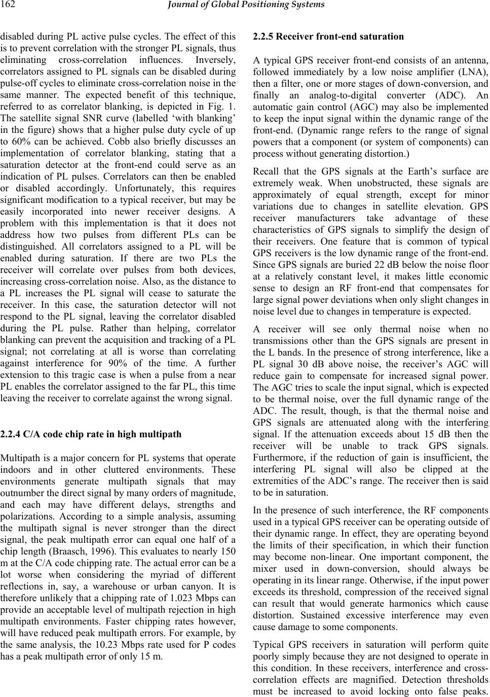 162 Journal of Global Positioning Systems disabled during PL active pulse cycles. The effect of this is to prevent correlation with the stronger PL signals, thus eliminating cross-correlation influences. Inversely, correlators assigned to PL signals can be disabled during pulse-off cycles to eliminate cross-correlation noise in the same manner. The expected benefit of this technique, referred to as correlator blanking, is depicted in Fig. 1. The satellite signal SNR curve (labelled ‘with blanking’ in the figure) shows that a higher pulse duty cycle of up to 60% can be achieved. Cobb also briefly discusses an implementation of correlator blanking, stating that a saturation detector at the front-end could serve as an indication of PL pulses. Correlators can then be enabled or disabled accordingly. Unfortunately, this requires significant modification to a typical receiver, but may be easily incorporated into newer receiver designs. A problem with this implementation is that it does not address how two pulses from different PLs can be distinguished. All correlators assigned to a PL will be enabled during saturation. If there are two PLs the receiver will correlate over pulses from both devices, increasing cross-correlation noise. Also, as the distance to a PL increases the PL signal will cease to saturate the receiver. In this case, the saturation detector will not respond to the PL signal, leaving the correlator disabled during the PL pulse. Rather than helping, correlator blanking can prevent the acquisition and tracking of a PL signal; not correlating at all is worse than correlating against interference for 90% of the time. A further extension to this tragic case is when a pulse from a near PL enables the correlator assigned to the far PL, this time leaving the receiver to correlate against the wrong signal. 2.2.4 C/A code chip rate in high multipath Multipath is a major concern for PL systems that operate indoors and in other cluttered environments. These environments generate multipath signals that may outnumber the direct signal by many orders of magnitude, and each may have different delays, strengths and polarizations. According to a simple analysis, assuming the multipath signal is never stronger than the direct signal, the peak multipath error can equal one half of a chip length (Braasch, 1996). This evaluates to nearly 150 m at the C/A code chipping rate. The actual error can be a lot worse when considering the myriad of different reflections in, say, a warehouse or urban canyon. It is therefore unlikely that a chipping rate of 1.023 Mbps can provide an acceptable level of multipath rejection in high multipath environments. Faster chipping rates however, will have reduced peak multipath errors. For example, by the same analysis, the 10.23 Mbps rate used for P codes has a peak multipath error of only 15 m. 2.2.5 Receiver front-end saturation A typical GPS receiver front-end consists of an antenna, followed immediately by a low noise amplifier (LNA), then a filter, one or more stages of down-conversion, and finally an analog-to-digital converter (ADC). An automatic gain control (AGC) may also be implemented to keep the input signal within the dynamic range of the front-end. (Dynamic range refers to the range of signal powers that a component (or system of components) can process without generating distortion.) Recall that the GPS signals at the Earth’s surface are extremely weak. When unobstructed, these signals are approximately of equal strength, except for minor variations due to changes in satellite elevation. GPS receiver manufacturers take advantage of these characteristics of GPS signals to simplify the design of their receivers. One feature that is common of typical GPS receivers is the low dynamic range of the front-end. Since GPS signals are buried 22 dB below the noise floor at a relatively constant level, it makes little economic sense to design an RF front-end that compensates for large signal power deviations when only slight changes in noise level due to changes in temperature is expected. A receiver will see only thermal noise when no transmissions other than the GPS signals are present in the L bands. In the presence of strong interference, like a PL signal 30 dB above noise, the receiver’s AGC will reduce gain to compensate for increased signal power. The AGC tries to scale the input signal, which is expected to be thermal noise, over the full dynamic range of the ADC. The result, though, is that the thermal noise and GPS signals are attenuated along with the interfering signal. If the attenuation exceeds about 15 dB then the receiver will be unable to track GPS signals. Furthermore, if the reduction of gain is insufficient, the interfering PL signal will also be clipped at the extremities of the ADC’s range. The receiver then is said to be in saturation. In the presence of such interference, the RF components used in a typical GPS receiver can be operating outside of their dynamic range. In effect, they are operating beyond the limits of their specification, in which their function may become non-linear. One important component, the mixer used in down-conversion, should always be operating in its linear range. Otherwise, if the input power exceeds its threshold, compression of the received signal can result that would generate harmonics which cause distortion. Sustained excessive interference may even cause damage to some components. Typical GPS receivers in saturation will perform quite poorly simply because they are not designed to operate in this condition. In these receivers, interference and cross- correlation effects are magnified. Detection thresholds must be increased to avoid locking onto false peaks.  Kanli: Limitations of Pseudolite Systems Using Off-The-Shelf GPS Receivers 163 Furthermore, a receiver can only track one saturating PL signal at a time, and only if it significantly stronger than the other PL signals. Two saturating PL signals of the same strength will interfere with each other so that neither can be accurately tracked. This has implications for pulsed PL networks. As mentioned in section 2.1.3, the active-phase of a pulse cycle from multiple PLs may overlap in time due to PL clock drift. This will decrease PL signal SNR, due to partial jamming, and may also cause tracking errors or prevent acquisition. The pulsing scheme of multiple PLs should be synchronized so that duty cycles do not coincide. In wide-area deployment of PLs attention must also be given to propagation delays that may cause some overlapping of adjacent synchronous PL pulses. A more thorough discussion of the effects of GPS receiver saturation is presented by Cobb (1997). 3 Impact of L1 C/A code issues on pseudolite applications This section will briefly outline how the presented issues may impact on PL usage for several different applications. 3.1 Aircraft approach and landing Legal: L1 C/A code PLs used for aiding aircraft navigation appear to be legal under FCC and ACA regulations. Jamming/Saturation: Radionavigation systems for aircraft are subject to stringent performance requirements. Therefore, any factors that limit the accuracy and reliability of these systems are of great concern. PLs must provide adequate coverage to enable aircraft to acquire and track their signals well before the landing approach. This involves distances of up to 15 km. In order to provide this coverage, PLs must transmit at high power, meaning receivers at closer distances will be saturated. The saturation of receivers by L1 C/A code PL signals limit the number of PLs that can be deployed around an airfield to about 2. Users in this system will be denied more PLs that could offer better geometry and provide extra ranging signals for reliability. The jamming effect of high power PL signals combined with saturation effects also degrades the performance of participating and non-participating receivers. 3.2 Integrated GPS/pseudolite positioning Legal: According to current FCC regulations, operating an L1 PL is illegal without an experimental radio station (or other) licence. It is unclear as to whether any changes in regulations will be made. For research work which typically involves limited intervals of PL transmission this legal obstacle may be considered minor. However, from a commercial perspective this is a major hurdle that stands in the way of implementing a round-the-clock L1 PL service which is integrated with GPS. Furthermore, under current ACA regulations designers and suppliers of L1 PLs, which may be considered as RNSS jamming devices, are liable to prosecution and heavy fines. Jamming/Saturation: From a consumer’s perspective, those who have bought and paid for GPS receivers that are either unable to track PL signals or are unable to handle even minimal interference from PL signals, are unlikely to support the deployment of L1 C/A code PLs in their area. PLs may instead be configured to transmit at low power, although this requires their deployment in increased numbers to provide the required coverage. 3.3 Indoor pseudolite-only systems Legal: Operating L1 PLs indoors without a licence, even at low power levels, is still considered illegal. Jamming/Saturation: It is difficult to maintain constant signal levels in cluttered indoor environments, even if the near-far effect was eliminated. PL signals will be received at power levels varying over a very wide range, especially if signals are required to propagate through walls and ceilings. A weak signal from an adjacent room will most likely be jammed by a closer PL. Also, current OTS receivers with their low dynamic range will exhibit difficulties in coping with the high range of PL signal strengths. Receivers may frequently move in and out of saturation. GPS signals indoors are so heavily attenuated that they are unusable by most receivers. From this perspective, the jamming of indoor GPS signals by L1 PLs could be forgiven. However, new Assisted-GPS (AGPS) techniques have been developed that enable special GPS receiver designs to acquire and track weak indoor signals. In this case, jamming GPS signals is still an issue for indoor systems. Multipath: By far the greatest limitation of L1 C/A code PLs in indoor applications is the low multipath mitigation offered by its signal structure. The chipping rate of the C/A code is just too low, leaving the receivers vulnerable to high multipath range errors. 4 Future directions Research into the use of PLs for many different applications has been conducted for over two decades. Throughout this time almost all of the experimentation has involved PLs using the civilian signal structure of GPS. The primary reason for this was that it enabled the  164 Journal of Global Positioning Systems use of existing receiver hardware with only minor firmware modifications. Innovative methods of incorporating PLs into navigation applications were developed. Promise in this new technology led several companies providing positioning solutions to develop and sell L1 C/A code PLs. However, to date the use of PLs has been limited to the realm of research or to highly specialized applications. The author believes that this is due to the various issues which limit the effectiveness of L1 C/A code PLs as discussed in the previous sections. With the development of Galileo and the modernization of GPS, some of the issues in this paper will be addressed. One is the faster chipping rate on civilian signals that will reduce maximum multipath errors; and the other is the two civilian frequencies that provide a means for ambiguity resolution. When both these systems are operational, PLs augmenting Galileo and modernized GPS on the new civilian signals will be able to provide some performance gains over the current PLs augmenting GPS. Unfortunately, no benefit will be gained with regards to jamming, interference or receiver saturation. Furthermore, if a provision for the use of PLs to augment the new signals is not defined, the same legal obstacles will remain in place, limiting their widespread use. A current trend in PL research and development is the movement away from preserving backward compatibility with existing GPS receivers. Most of the ideas are not new, but the driving force behind them is a recent realization that a signal structure used for global positioning cannot always be used for local positioning, especially indoors. One of the ideas being implemented is multi-frequency transmissions in the Industrial Scientific and Medical (ISM) band (Zimmerman et al, 2000). Operating in the ISM band requires no licence, as long as the maximum power output is limited to less than 1 Watt (FCC-47CFR15.247). The major advantage gained is the legal freedom to transmit on multiple bands, including 915 MHz, 2.45 GHz and 5.8 GHz. Receivers can exploit the frequency diversity to resolve carrier cycle ambiguities. On the other hand, there may be interference issues with other devices that also use the ISM band, such as cordless phones and 802.11b/g. Locata Corporation, an Australian company based in Canberra, is currently developing PL technology for operation in the ISM band. Locata Corporation is building on the success of its synchronous L1 prototype PLs that have proven accurate performance in an indoor, high multipath environment (Barnes et al, 2004). A Locata PL, called a LocataLite, is an intelligent transceiver that transmits on dual frequencies in the ISM band. A LocataLite is able to synchronize to the transmissions of other LocataLites, forming a synchronous positioning network called a LocataNet. A receiver device, called a Locata, can determine its position within the LocataNet using both code and carrier phase measurements. The main advantage offered by a LocataNet is its synchronous signals, which allow standalone navigation and precise time transfer. Novariant (formerly IntegriNautics) has also developed an off-frequency PL system called a TerraliteTM (Novariant, 2004). A TerraliteTM transmits a proprietary signal called XPS. At the time of writing, little public information was available on the frequency or signal structure of the XPS signal, though the requirement for a licence was announced. Novariant also provides a tri- frequency receiver that is able to track both L1 and L2 GPS signals in addition to the XPS signal. Novariant is targeting specialized heavy industries, such as mining, where GPS is one of the primary positioning systems used. In such industries considerable investment has been made into GPS receivers and even into L1 C/A code PLs in order to address their positioning needs. However, in light of the issues discussed in the previous sections, this can only provide limited performance. The TerraliteTM XPS signal offers an additional signal designed to overcome the restrictions of L1 PLs that are currently used. Furthermore, the ability of the XPS receiver to also receive both L1 and L2 signals means that a client’s existing GPS infrastructure can still be utilized. Multi-frequency PLs can complicate the design of the front-end of receivers that are intended to process them. For example the Novariant XPS receiver, which must acquire L1, L2 and a third frequency. The number of components required will increase; especially if separate RF paths are to be used for each frequency. This can add significant cost to receivers. Currently, research is being performed on reducing the need for a complicated front- end by using direct sampling instead (Psiaki et al, 2003). Another development in receiver technology is the software correlator receiver. These receivers perform all signal processing tasks after digital conversion, including correlation, within a multi-purpose processor. Software receivers can offer flexibility in adapting to the various signal modulation plans of future PL systems. However, significant processing power will be required for processing signals with high chipping rates. Pany and Eissfeller (2004) address this performance issue by using sub-Nyquist sample rates. In the past, jamming of GPS signals has been primarily a concern for the military. However, beyond military concerns are civilian vulnerabilities related to critical infrastructure. Cell phone networks, commercial fishing, transportation, emergency response, air navigation and air traffic control; all have developed a reliance on GPS for timing and navigation. The list of dependencies will grow as accurate position information becomes more tightly integrated into business practices. This is expected to spur the development of more robust receivers to address some of the issues in jamming and interference.  Kanli: Limitations of Pseudolite Systems Using Off-The-Shelf GPS Receivers 165 For indoor positioning, the high multipath environment necessitates the use of more robust signal structures. An example is Locata Corporation’s synchronously pulsed signals with fast chipping rates. Also, their use of multiple frequencies provides redundancy to protect against multipath fades. Another is presented by Progri et al (2004), who propose a very unique indoor positioning system using ultra-wideband (UWB) signals. This system uses orthogonal frequency division multiplexing (OFDM) with frequency division multiple access (FDMA) that minimizes cross-channel interference. The UWB signals also offer good protection from multipath fades. Other techniques for indoor positioning have been proposed. One is Siemen’s Local Positioning Radar (LPR) system (Siemens, 2004). This system comprises of transponders that are deployed around the area of interest. A base station transmits pulses which are received and retransmitted by each transponder. The base station will receive each retransmitted signal at different times according to its distance from each transponder, hence providing range information. Another is a UWB time-of- arrival (TOA) technique (Fontana and Gunderson, 2002). In this system, passive receivers in a chained network detect the pulsed transmissions from active UWB tags. TOA data from the receivers are then processed to determine the position of each active UWB tag. Assisted GPS (AGPS) techniques provided by Global Locate, SiRF and Q-Comm use massively parallel correlator architectures to detect the heavily attenuated GPS signals indoors (Global Locate, 2004). To do this, a data link provides known navigation messages to the AGPS receiver, enabling it to integrate for longer periods. However, considerable infrastructure is needed to provide navigation messages to all users. Rosum Corporation proposes the use of digital television signals to augment GPS (Rosum, 2004). TV signals use a variety of VHF and UHF bands, hence giving protection against multipath fades. Their signals are also stronger than GPS signals by about 40 dB. However, this technique also requires significant infrastructure to monitor channel stability and timing information. Also, currently receivers using this technology are unable to calculate their own position; this is performed at a location server and sent back to a receiver because current TV signals are not synchronous to a common clock. In some of the techniques above, the position of a location device is determined by the system, not by the device itself. This may be desirable for applications such as centralized asset management, but would be unsuitable for other applications such as autonomous robotics or guidance and control. Furthermore, the reliance on data links for navigation messages or timing information may be a hindrance. For these and other reasons, the author believes that it is unlikely for any single positioning system to be the answer to every application’s needs. What the author does believe is important, though, is that the users of positioning technology should have full control over their signals. Only then can a positioning system be optimized to best suit one’s needs. 5 Conclusions L1 C/A code PLs simplify experimentation with PL technology. They allow the convenient use of existing OTS GPS receivers. However, this practicality has disadvantages. One involves the legal issues of transmitting on L1, a band protected globally by legislation. L1 PLs can also jam GPS signals, denying GPS to non-participating receivers. The C/A code chipping rate used by these PLs also does not provide sufficient protection against multipath. Typical OTS GPS receivers are easily saturated by strong PL signals; this limits the accuracy and reliability of the PL system. These factors add further complications to general PL issues such as near-far, multipath and synchronization. A current trend in PL development serves to address these complications by moving off the L1 frequency and using more robust signal structures. 7 Acknowledgements The author would like to thank Dr. Jimmy Lamance, Dave Small, Dr. Joel Barnes, and Dr Dorota Grejner- Brzezinska for their valuable input and assistance. References ACA (2004): Media Release No. 73, 1 September, http://www.aca.gov.au/aca_home/media_releases/media_e nquiries/2004/04-73.htm Barnes J.; Rizos C.; Wang J.; Small D.; Voigt G.; Gambale N. (2003): High precision indoor and outdoor positioning using LocataNet, 2003 Int. Symp. on GPS/GNSS, Tokyo, Japan, 15-18 November, 9-18 Barnes J.; Rizos C.; Kanli M.; Small D.; Voigt G.; Gambale N.; Lamance J.; Nunan T.; Reid C. (2004): Indoor industrial machine guidance using Locata: A pilot study at BlueScope Steel, Proceedings of the 60th Annual Meeting of the U.S. Inst. Of Navigation, Dayton, Ohio, 7-9 June, 533-540. Braasch M.S. (1996): Multipath Effects, Global Positioning System: Theory and Applications I, AIAA, 547-568. Cobb H.S. (1997): GPS pseudolites: Theory, design, and applications, PhD Dissertation, Stanford University. Dai L.; Wang J.; Tsujii T.; Rizos C. (2001): Pseudolite Applications in Positioning and Navigation: Modelling and Geometric Analysis, Int. Symp. on Kinematic Systems  166 Journal of Global Positioning Systems in Geodesy, Geomatics & Navigation, Banff, Canada, 5-8 June, 482-489. Fontana R.J.; Gunderson S.J.; (2002): Ultra-WideBand Precision Asset Location System, IEEE Conference on Ultra Wideband Systems and Technologies, May 2002, Baltimore, MD. Forssell B.; Olsen T.B. (2003): Jamming GPS: Susceptibility of Some Civil GPS Receivers, GPS World, Vol. 14, No. 1, January, 54-58. Global Locate (2004): Global Locate: Home, http://www.globallocate.com Irsigler M.; Eissfeller B. (2003): Comparison of Multipath Mitigation Techniques with Consideration of Future Signal Structures, Proceedings of the 16th Int. Tech. Meeting of the Satellite Division of the U.S. Inst. of Navigation, Portland, Oregon, 9-12 September, 2584-2592. Klein D.; Parkinson B.W. (1986): The use of pseudo-satellites for improving GPS performance, Global Positioning System (red book), Vol III, Institute of Navigation, 135- 146. Kee C.; Jun H.; Yun D. (2000): Development of Indoor Navigation System using Asynchronous Pseudolites, Proceedings of US Institute of Navigation GPS-2000, Salt Lake City, Utah, 19-22 September, 1038-1045. Kunysz W. (2003): A Three Dimensional Choke Ring Ground Plane Antenna, Proceedings of the 16th Int. Tech. Meeting of the Satellite Division of the U.S. Inst. of Navigation, Portland, Oregon, 9-12 September, 1883-1888. Wang J.; Lee H.K. (2002): Impact of Pseudolite Location Errors on Positioning, Geomatics Research Australasia, 77, 81-94. Madhani P.H.; Axelrad P. (2001): Mitigation of the Near-Far Problem by Successive Interference Cancellation, Proceedings of the 14th Int. Tech. Meeting of the Satellite Division of the U.S. Inst. of Navigation, Salt Lake City, Utah, 11-14 September, 148-154. Misra P.; Enge P. (2001): Global Positioning System: Signals, Measurements, and Performance, Ganga-Jamuna Press, Lincoln, Massachusetts, 2001. Novariant (2004): Novariant: Mining – Products, http://www.novariant.com/mining/products/index.cfm Pany T.; Eissfeller B. (2004): Code and Phase Tracking of Generic PRN Signals with Sub-Nyquist Sample Rates, Journal of the Institute of Navigation, Vol. 51, No. 2, Summer 2004, 143-159. Progri I.F.; Michalson W.R.; Cyganski D. (2004): An OFDM/FDMA Indoor Geolocation System, Journal of the Institute of Navigation, Vol. 51, No. 2, Summer 2004, 133- 142. Psiaki M.L.; Powell S.P.; Jung H.; Kintner Jr. P.M. (2003): Design and Practical Implementation of Multi- Frequency RF Front Ends Using Direct RF Sampling, Proceedings of the 16th Int. Tech. Meeting of the Satellite Division of the U.S. Inst. of Navigation, Portland, Oregon, 9-12 September, 90-102. Rosum (2004): Rosum Corporation. Reliable Location. Inside and Out, http://www.rosum.com Rounds S (2004a): Jamming protection of GPS receivers; Part I: Receiver Enhancements, GPS World, Vol. 15, No. 1, January. Rounds S (2004b): Jamming protection of GPS receivers; Part II: Antenna Enhancements, GPS World, Vol. 15, No. 2, February, 38 - 45. Siemens (2004): Methods and Apparatus for Determining a Location of a Device, United States Patent Application Publication No. US 2004/0157625 A1. Söderholm S.; Juhola T.; Saarnimo T.; Karttunen V. (2001): Indoor Navigation Using a GPS Receiver, Proceedings of the 14th Int. Tech. Meeting of the Satellite Division of the U.S. Inst. of Navigation, Salt Lake City, Utah, 11-14 September, 1479-1486. Söderholm S.; Jokitalo T. (2002): Synchronized Pseudolites - The Key to Indoor Navigation, Proceedings of the 16th Int. Tech. Meeting of the Satellite Division of the U.S. Inst. of Navigation, Portland, Oregon, 9-12 September, 226- 230. Soon B.H.K.; Poh E.K.; Barnes J.; Zhang J.; Lee H.K.; Lee H.K.; Rizos C. (2003): Flight test results of precision approach and landing augmented by airport pseudolites, Proceedings of the 16th Int. Tech. Meeting of the Satellite Division of the U.S. Institute of Navigation, Portland, Oregon, 9-12 September, 2318-2325. Stolk K.; Brown A. (2003): Phase Center Calibration and Multipath Test Results of a Digital Beam-Steered Antenna Array, Proceedings of the 16th Int. Tech. Meeting of the Satellite Division of the U.S. Institute of Navigation, Portland, Oregon, 9-12 September, 1889-1897. Van Dierendonck A.; Fenton P.; Ford T. (1992): Theory and Performance of Narrow Correlator Spacing in a GPS Receiver, Navigation, Volume 39, Number 3, 265-283. Wang J (2002) Pseudolite Applications in Positioning and Navigation: Progress and problems, Journal of Global Positioning Systems, 1(1): 48-56. Weiss J.P.; Anderson S.; Axelrad P. (2003): Multipath Modeling and Test Results for JPALS Ground Station Receivers, Proceedings of the 16th Int. Tech. Meeting of the Satellite Division of the U.S. Inst. of Navigation, Portland, Oregon, 9-12 September, 1801-1811. Yun D.; Kee C. (2002): Centimeter Accuracy Stand-alone Indoor Navigation System By Synchronized Pseudolite Constellation, Proceedings of the 16th Int. Tech. Meeting of the Satellite Division of the U.S. Inst. of Navigation, Portland, Oregon, 9-12 September, 213-225. Zimmerman K.R.; Cohen C.E.; Lawrence D.G.; Montgomery P.Y.; Cobb H.S.; Melto W.C. (2000): Multi-Frequency Pseudolites for Instantaneous Carrier Ambiguity Resolution, Proceedings of US Institute of Navigation GPS-2000, Salt Lake City, Utah, 19-22 September, 1024- 1030. |