Paper Menu >>
Journal Menu >>
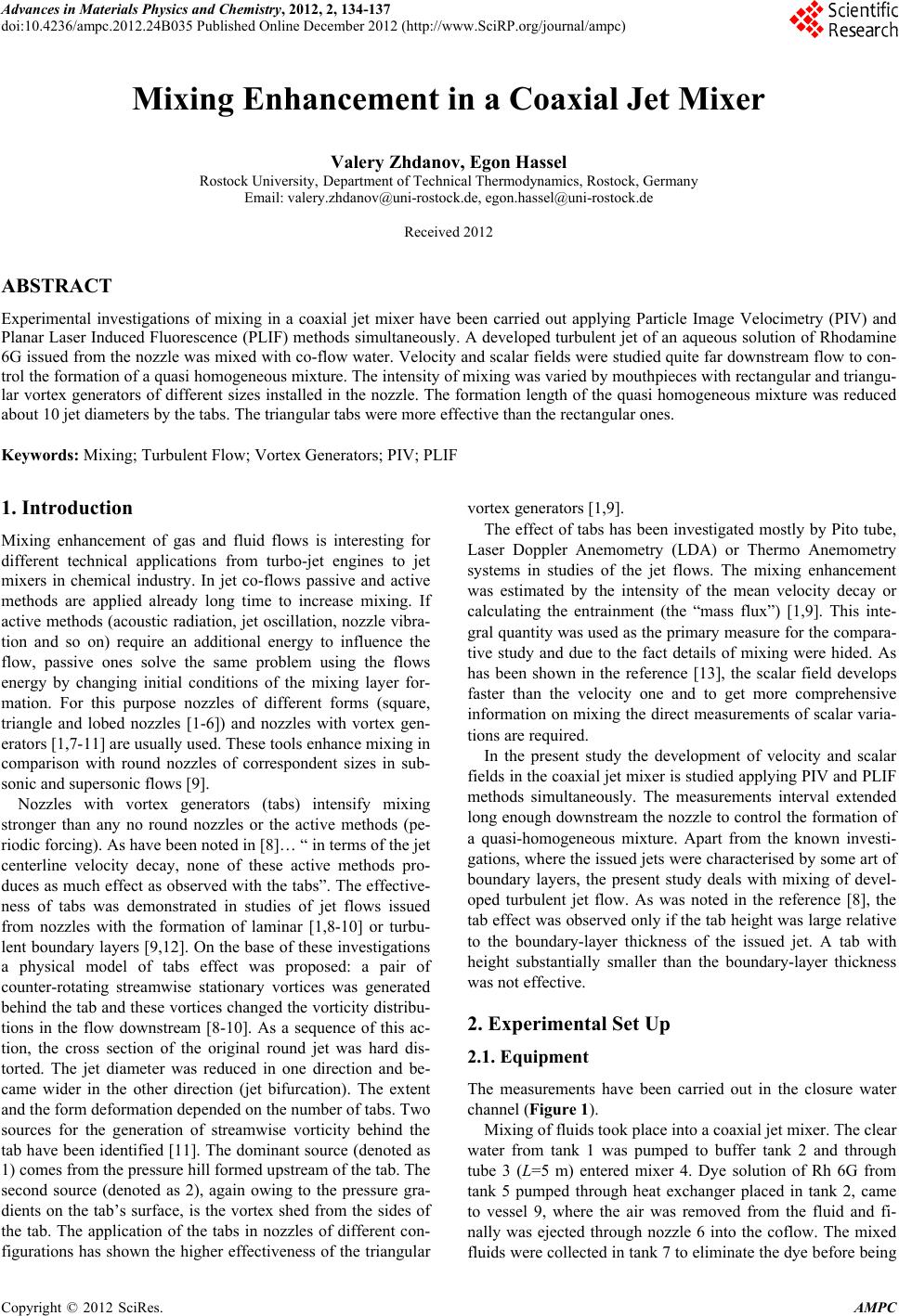 Advances in Materials Physics and Chemistry, 2012, 2, 134-137 doi:10.4236/ampc.2012.24B035 Published Online December 2012 (http://www.SciRP.org/journal/ampc) Mixing Enhancement in a Coaxial Jet Mixer Valery Zhdanov, Egon Hassel Rostock University, Department of Technical Thermodynamics, Rostock, Germany Email: valery.zhdanov@uni-rostock.de, egon.hassel@uni-rostock.de Received 2012 ABSTRACT Experimental investigations of mixing in a coaxial jet mixer have been carried out applying Particle Image Velocimetry (PIV) and Planar Laser Induced Fluorescence (PLIF) methods simultaneously. A developed turbulent jet of an aqueous solution of Rhodamine 6G issued from the nozzle was mixed with co-flow water. Velocity and scalar fields were studied quite far downstream flow to con- trol the formation of a quasi homogeneous mixture. The intensity of mixing was varied by mouthpieces with rectangular and triangu- lar vortex generators of different sizes installed in the nozzle. The formation length of the quasi homogeneous mixture was reduced about 10 jet diameters by the tabs. The triangular tabs were more effective than the rectangular ones. Keywords: Mixing; Turbulent Flow; Vortex Generators; PIV; PLIF 1. Introduction Mixing enhancement of gas and fluid flows is interesting for different technical applications from turbo-jet engines to jet mixers in chemical industry. In jet co-flows passive and active methods are applied already long time to increase mixing. If active methods (acoustic radiation, jet oscillation, nozzle vibra- tion and so on) require an additional energy to influence the flow, passive ones solve the same problem using the flows energy by changing initial conditions of the mixing layer for- mation. For this purpose nozzles of different forms (square, triangle and lobed nozzles [1-6]) and nozzles with vortex gen- erators [1,7-11] are usually used. These tools enhance mixing in comparison with round nozzles of correspondent sizes in sub- sonic and supersonic flows [9]. Nozzles with vortex generators (tabs) intensify mixing stronger than any no round nozzles or the active methods (pe- riodic forcing). As have been noted in [8]… “ in terms of the jet centerline velocity decay, none of these active methods pro- duces as much effect as observed with the tabs”. The effective- ness of tabs was demonstrated in studies of jet flows issued from nozzles with the formation of laminar [1,8-10] or turbu- lent boundary layers [9,12]. On the base of these investigations a physical model of tabs effect was proposed: a pair of counter-rotating streamwise stationary vortices was generated behind the tab and these vortices changed the vorticity distribu- tions in the flow downstream [8-10]. As a sequence of this ac- tion, the cross section of the original round jet was hard dis- torted. The jet diameter was reduced in one direction and be- came wider in the other direction (jet bifurcation). The extent and the form deformation depended on the number of tabs. Two sources for the generation of streamwise vorticity behind the tab have been identified [11]. The dominant source (denoted as 1) comes from the pressure hill formed upstream of the tab. The second source (denoted as 2), again owing to the pressure gra- dients on the tab’s surface, is the vortex shed from the sides of the tab. The application of the tabs in nozzles of different con- figurations has shown the higher effectiveness of the triangular vortex generators [1,9]. The effect of tabs has been investigated mostly by Pito tube, Laser Doppler Anemometry (LDA) or Thermo Anemometry systems in studies of the jet flows. The mixing enhancement was estimated by the intensity of the mean velocity decay or calculating the entrainment (the “mass flux”) [1,9]. This inte- gral quantity was used as the primary measure for the compara- tive study and due to the fact details of mixing were hided. As has been shown in the reference [13], the scalar field develops faster than the velocity one and to get more comprehensive information on mixing the direct measurements of scalar varia- tions are required. In the present study the development of velocity and scalar fields in the coaxial jet mixer is studied applying PIV and PLIF methods simultaneously. The measurements interval extended long enough downstream the nozzle to control the formation of a quasi-homogeneous mixture. Apart from the known investi- gations, where the issued jets were characterised by some art of boundary layers, the present study deals with mixing of devel- oped turbulent jet flow. As was noted in the reference [8], the tab effect was observed only if the tab height was large relative to the boundary-layer thickness of the issued jet. A tab with height substantially smaller than the boundary-layer thickness was not effective. 2. Experimental Set Up 2.1. Equipment The measurements have been carried out in the closure water channel (Figure 1). Mixing of fluids took place into a coaxial jet mixer. The clear water from tank 1 was pumped to buffer tank 2 and through tube 3 (L=5 m) entered mixer 4. Dye solution of Rh 6G from tank 5 pumped through heat exchanger placed in tank 2, came to vessel 9, where the air was removed from the fluid and fi- nally was ejected through nozzle 6 into the coflow. The mixed fluids were collected in tank 7 to eliminate the dye before being Copyright © 2012 SciRes. AMPC 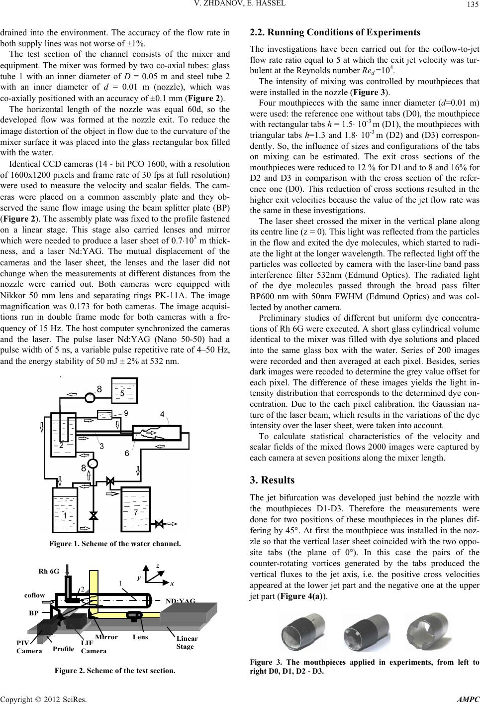 V. ZHDANOV, E. HASSEL 135 drained into the environment. The accuracy of the flow rate in both supply lines was not worse of 1%. The test section of the channel consists of the mixer and equipment. The mixer was formed by two co-axial tubes: glass tube 1 with an inner diameter of D = 0.05 m and steel tube 2 with an inner diameter of d = 0.01 m (nozzle), which was co-axially positioned with an accuracy of ±0.1 mm (Figure 2). The horizontal length of the nozzle was equal 60d, so the developed flow was formed at the nozzle exit. To reduce the image distortion of the object in flow due to the curvature of the mixer surface it was placed into the glass rectangular box filled with the water. Identical CCD cameras (14 - bit PCO 1600, with a resolution of 1600x1200 pixels and frame rate of 30 fps at full resolution) were used to measure the velocity and scalar fields. The cam- eras were placed on a common assembly plate and they ob- served the same flow image using the beam splitter plate (BP) (Figure 2). The assembly plate was fixed to the profile fastened on a linear stage. This stage also carried lenses and mirror which were needed to produce a laser sheet of 0.7103 m thick- ness, and a laser Nd:YAG. The mutual displacement of the cameras and the laser sheet, the lenses and the laser did not change when the measurements at different distances from the nozzle were carried out. Both cameras were equipped with Nikkor 50 mm lens and separating rings PK-11A. The image magnification was 0.173 for both cameras. The image acquisi- tions run in double frame mode for both cameras with a fre- quency of 15 Hz. The host computer synchronized the cameras and the laser. The pulse laser Nd:YAG (Nano 50-50) had a pulse width of 5 ns, a variable pulse repetitive rate of 4–50 Hz, and the energy stability of 50 mJ ± 2% at 532 nm. Figure 1. Scheme of the water channel. ND:YAG LIF Camera PIV Camera Lens co fl ow Rh 6G Linear Stage BP Mirror 1 2 Pr o fil e x y z Figure 2. Scheme of the test section. 2.2. Running Conditions of Experiments The investigations have been carried out for the coflow-to-jet flow rate ratio equal to 5 at which the exit jet velocity was tur- bulent at the Reynolds number Red =104. The intensity of mixing was controlled by mouthpieces that were installed in the nozzle (Figure 3). Four mouthpieces with the same inner diameter (d=0.01 m) were used: the reference one without tabs (D0), the mouthpiece with rectangular tabs h = 1.5 10-3 m (D1), the mouthpieces with triangular tabs h=1.3 and 1.8 10-3 m (D2) and (D3) correspon- dently. So, the influence of sizes and configurations of the tabs on mixing can be estimated. The exit cross sections of the mouthpieces were reduced to 12 % for D1 and to 8 and 16% for D2 and D3 in comparison with the cross section of the refer- ence one (D0). This reduction of cross sections resulted in the higher exit velocities because the value of the jet flow rate was the same in these investigations. The laser sheet crossed the mixer in the vertical plane along its centre line (z = 0). This light was reflected from the particles in the flow and exited the dye molecules, which started to radi- ate the light at the longer wavelength. The reflected light off the particles was collected by camera with the laser-line band pass interference filter 532nm (Edmund Optics). The radiated light of the dye molecules passed through the broad pass filter BP600 nm with 50nm FWHM (Edmund Optics) and was col- lected by another camera. Preliminary studies of different but uniform dye concentra- tions of Rh 6G were executed. A short glass cylindrical volume identical to the mixer was filled with dye solutions and placed into the same glass box with the water. Series of 200 images were recorded and then averaged at each pixel. Besides, series dark images were recoded to determine the grey value offset for each pixel. The difference of these images yields the light in- tensity distribution that corresponds to the determined dye con- centration. Due to the each pixel calibration, the Gaussian na- ture of the laser beam, which results in the variations of the dye intensity over the laser sheet, were taken into account. To calculate statistical characteristics of the velocity and scalar fields of the mixed flows 2000 images were captured by each camera at seven positions along the mixer length. 3. Results The jet bifurcation was developed just behind the nozzle with the mouthpieces D1-D3. Therefore the measurements were done for two positions of these mouthpieces in the planes dif- fering by 45°. At first the mouthpiece was installed in the noz- zle so that the vertical laser sheet coincided with the two oppo- site tabs (the plane of 0°). In this case the pairs of the counter-rotating vortices generated by the tabs produced the vertical fluxes to the jet axis, i.e. the positive cross velocities appeared at the lower jet part and the negative one at the upper jet part (Figure 4(a)). Figure 3. The mouthpieces applied in experiments, from left to right D0, D1, D2 - D3. Copyright © 2012 SciRes. AMPC 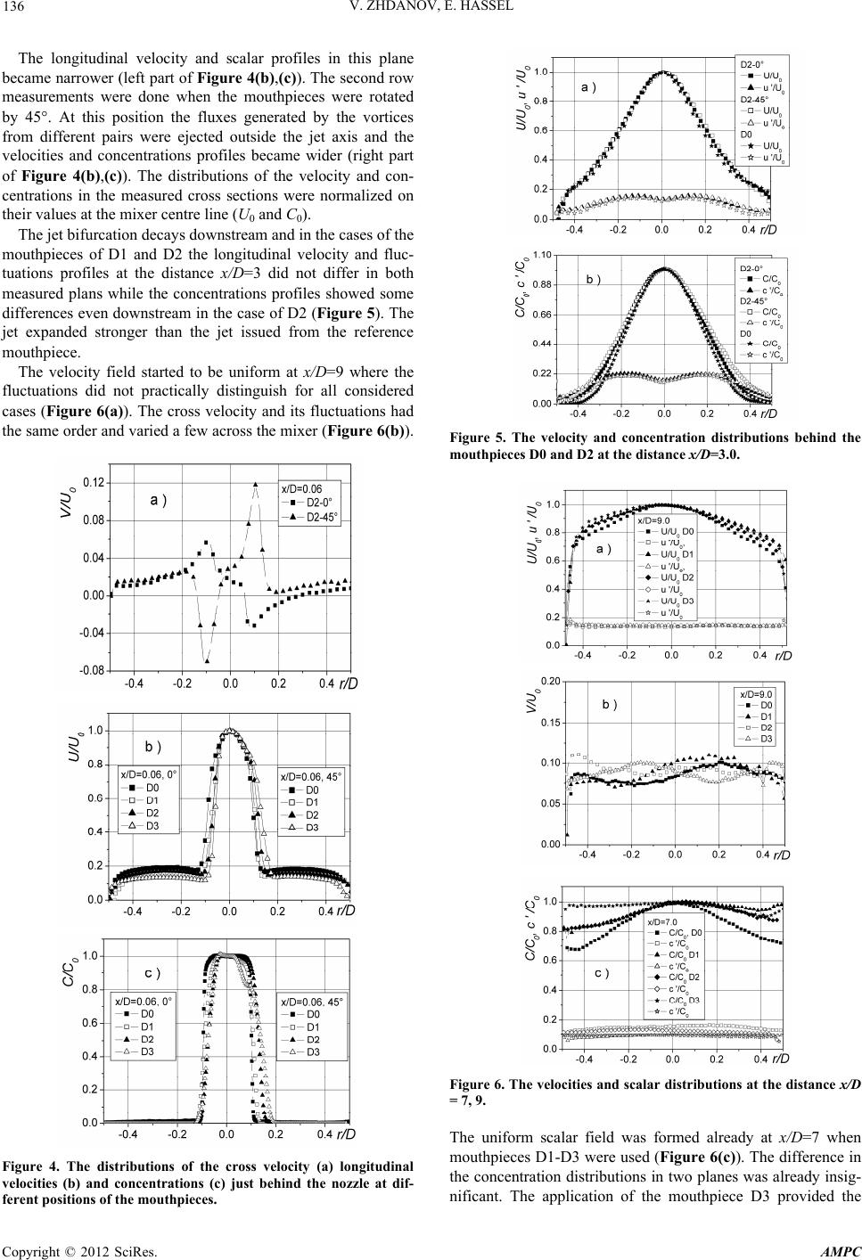 V. ZHDANOV, E. HASSEL 136 The longitudinal velocity and scalar profiles in this plane be ases of the m y field started to be uniform at x/D=9 where the fl came narrower (left part of Figure 4(b),(c)). The second row measurements were done when the mouthpieces were rotated by 45°. At this position the fluxes generated by the vortices from different pairs were ejected outside the jet axis and the velocities and concentrations profiles became wider (right part of Figure 4(b),(c)). The distributions of the velocity and con- centrations in the measured cross sections were normalized on their values at the mixer centre line (U0 and C0). The jet bifurcation decays downstream and in the c outhpieces of D1 and D2 the longitudinal velocity and fluc- tuations profiles at the distance x/D=3 did not differ in both measured plans while the concentrations profiles showed some differences even downstream in the case of D2 (Figure 5). The jet expanded stronger than the jet issued from the reference mouthpiece. The velocit uctuations did not practically distinguish for all considered cases (Figure 6(a)). The cross velocity and its fluctuations had the same order and varied a few across the mixe r (Figure 6(b)). Figure 4. The distributions of the cross velocity (a) longitudinal velocities (b) and concentrations (c) just behind the nozzle at dif- ferent positions of the mouthpieces. Figure 5. The velocity and concentration distributions behind the mouthpieces D0 and D2 at the distance x/D=3.0. Figure 6. The velocities and scalar distributions at the distance x/D he uniform scalar field was formed already at x/D=7 when = 7, 9. T mouthpieces D1-D3 were used (Figure 6(c)). The difference in the concentration distributions in two planes was already insig- nificant. The application of the mouthpiece D3 provided the Copyright © 2012 SciRes. AMPC 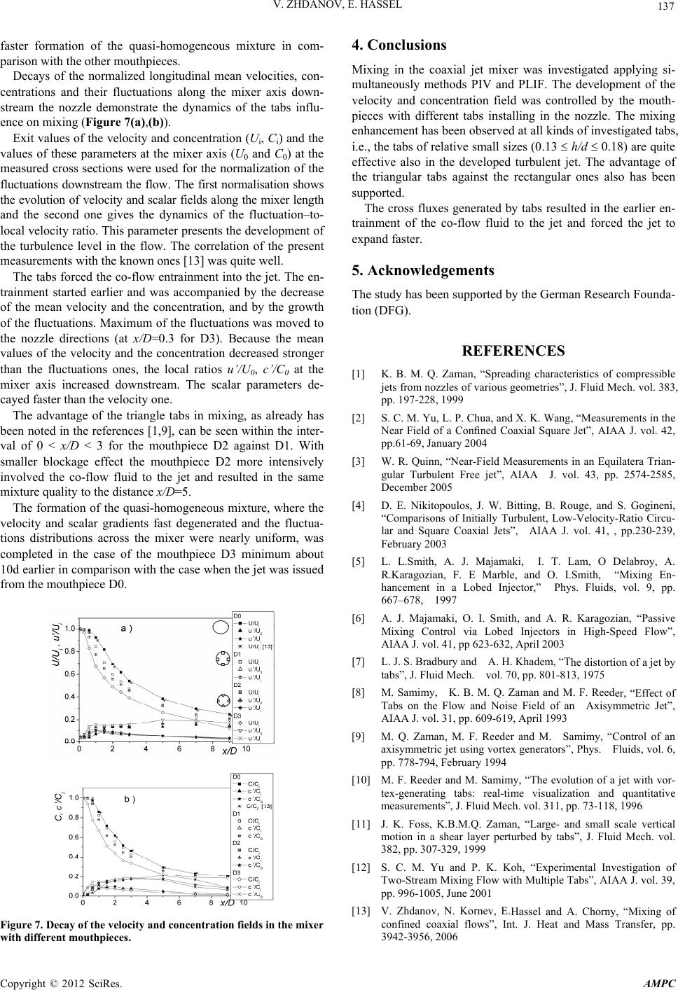 V. ZHDANOV, E. HASSEL Copyright © 2012 SciRes. AMPC 137 inal mean velocities, con- ce oncentration (U, C) and the va e en- tr s in mixing, as already has be us mixture, where the ve faster formation of the quasi-homogeneous mixture in com- parison with the other mouthpieces. Decays of the normalized longitud ntrations and their fluctuations along the mixer axis down- stream the nozzle demonstrate the dynamics of the tabs influ- ence on mixing (Figure 7(a),(b)). Exit values of the velocity and ci i lues of these parameters at the mixer axis (U0 and C0) at the measured cross sections were used for the normalization of the fluctuations downstream the flow. The first normalisation shows the evolution of velocity and scalar fields along the mixer length and the second one gives the dynamics of the fluctuation–to- local velocity ratio. This parameter presents the development of the turbulence level in the flow. The correlation of the present measurements with the known ones [13] was quite well. The tabs forced the co-flow entrainment into the jet. Th ainment started earlier and was accompanied by the decrease of the mean velocity and the concentration, and by the growth of the fluctuations. Maximum of the fluctuations was moved to the nozzle directions (at x/D=0.3 for D3). Because the mean values of the velocity and the concentration decreased stronger than the fluctuations ones, the local ratios u’/U0, c’/C0 at the mixer axis increased downstream. The scalar parameters de- cayed faster than the velocity one. The advantage of the triangle tab en noted in the references [1,9], can be seen within the inter- val of 0 < x/D < 3 for the mouthpiece D2 against D1. With smaller blockage effect the mouthpiece D2 more intensively involved the co-flow fluid to the jet and resulted in the same mixture quality to the distance x/D=5. The formation of the quasi-homogeneo locity and scalar gradients fast degenerated and the fluctua- tions distributions across the mixer were nearly uniform, was completed in the case of the mouthpiece D3 minimum about 10d earlier in comparison with the case when the jet was issued from the mouthpiece D0. Figure 7. Decay of the velocity and concentration fields inhe l jet mixer was investigated applying si- fluxes generated by tabs resulted in the earlier en- tr y the German Research Founda- [1] K. B. M. Q. Zamristics of compressible and X. K. Wang, “Measurements in the d Measurements in an Equilatera Trian- os, J. W. Bitting, B. Rouge, and S. Gogineni, J. Majamaki, I. T. Lam, O Delabroy, A. mith, and A. R. Karagozian, “Passive he distortion of a jet by er, “Effect of mimy, “Control of an y, “The evolution of a jet with vor- rtical . Koh, “Experimental Investigation of Hassel and A. Chorny, “Mixing of tmixer confined coaxial flows”, Int. J. Heat and Mass Transfer, pp. 3942-3956, 2006 with different mouthpieces. 4. Conclusions Mixing in the coaxia multaneously methods PIV and PLIF. The development of the velocity and concentration field was controlled by the mouth- pieces with different tabs installing in the nozzle. The mixing enhancement has been observed at all kinds of investigated tabs, i.e., the tabs of relative small sizes (0.13 h/d 0.18) are quite effective also in the developed turbulent jet. The advantage of the triangular tabs against the rectangular ones also has been supported. The cross ainment of the co-flow fluid to the jet and forced the jet to expand faster. 5. Acknowledgements The study has been supported b tion (DFG). REFERENCES an, “Spreading characte jets from nozzles of various geometries”, J. Fluid Mech. vol. 383, pp. 197-228, 1999 [2] S. C. M. Yu, L. P. Chua, Near Field of a Confined Coaxial Square Jet”, AIAA J. vol. 42, pp.61-69, January 2004 [3] W. R. Quinn, “Near-Fiel gular Turbulent Free jet”, AIAA J. vol. 43, pp. 2574-2585, December 2005 [4] D. E. Nikitopoul “Comparisons of Initially Turbulent, Low-Velocity-Ratio Circu- lar and Square Coaxial Jets”, AIAA J. vol. 41, , pp.230-239, February 2003 [5] L. L.Smith, A. R.Karagozian, F. E Marble, and O. I.Smith, “Mixing En- hancement in a Lobed Injector,” Phys. Fluids, vol. 9, pp. 667–678, 1997 [6] A. J. Majamaki, O. I. S Mixing Control via Lobed Injectors in High-Speed Flow”, AIAA J. vol. 41, pp 623-632, April 2003 [7] L. J. S. Bradbury and A. H. Khadem, “T tabs”, J. Fluid Mech. vol. 70, pp. 801-813, 1975 [8] M. Samimy, K. B. M. Q. Zaman and M. F. Reed Tabs on the Flow and Noise Field of an Axisymmetric Jet”, AIAA J. vol. 31, pp. 609-619, April 1993 [9] M. Q. Zaman, M. F. Reeder and M. Sa axisymmetric jet using vortex generators”, Phys. Fluids, vol. 6, pp. 778-794, February 1994 [10] M. F. Reeder and M. Samim tex-generating tabs: real-time visualization and quantitative measurements”, J. Fluid Mech. vol. 311, pp. 73-118, 1996 [11] J. K. Foss, K.B.M.Q. Zaman, “Large- and small scale ve motion in a shear layer perturbed by tabs”, J. Fluid Mech. vol. 382, pp. 307-329, 1999 [12] S. C. M. Yu and P. K Two-Stream Mixing Flow with Multiple Tabs”, AIAA J. vol. 39, pp. 996-1005, June 2001 [13] V. Zhdanov, N. Kornev, E. |