Paper Menu >>
Journal Menu >>
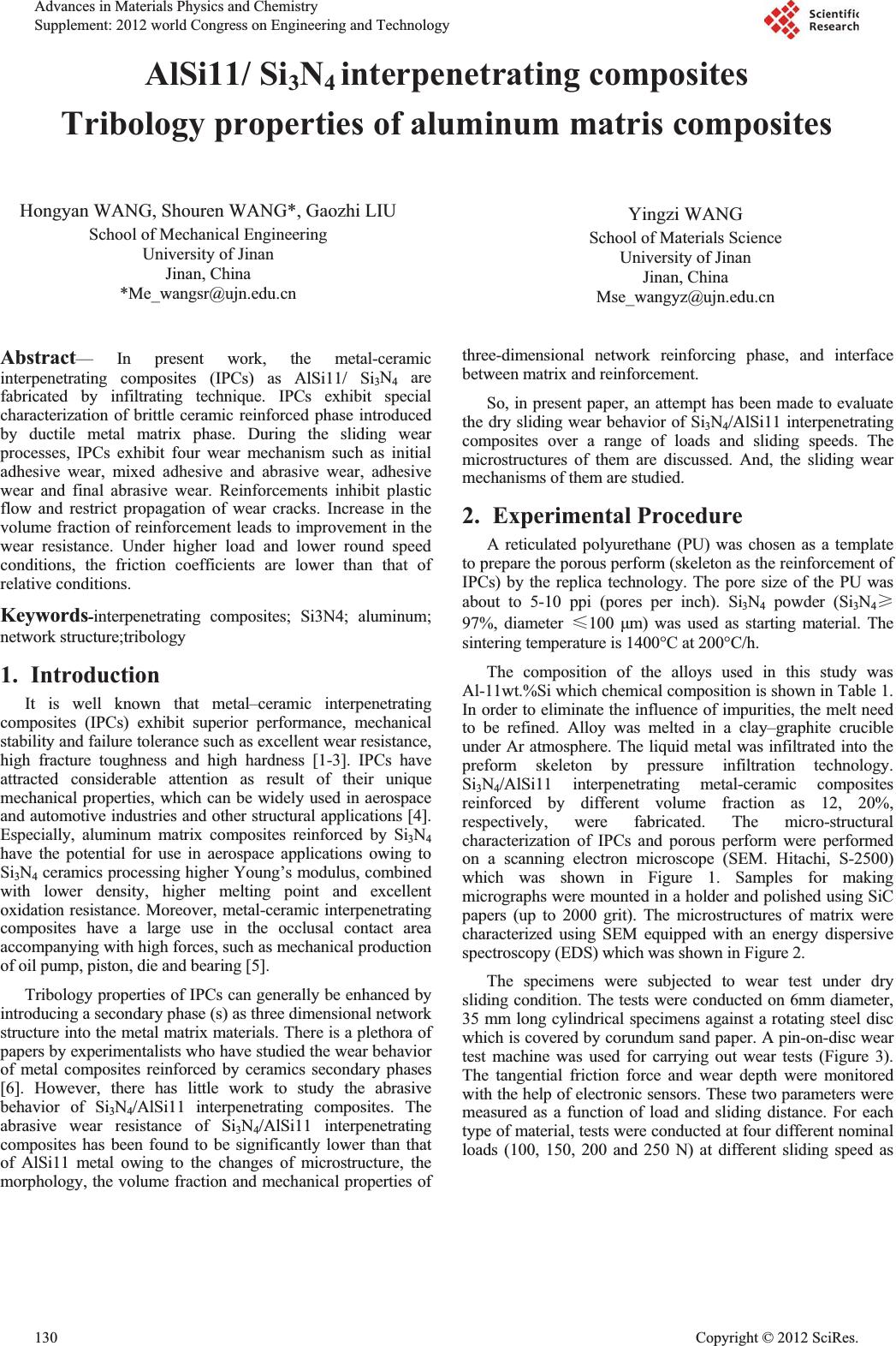 AlSi11/ Si3N4 interpenetrating composites Tribology properties of aluminum matris composites Hongyan WANG, Shouren WANG*, Gaozhi LIU School of Mechanical Engineering University of Jinan Jinan, China *Me_wangsr@ujn.edu.cn Yingzi WANG School of Materials Science University of Jinan Jinan, China Mse_wangyz@ujn.edu.cn Abstract— In present work, the metal-ceramic interpenetrating composites (IPCs) as AlSi11/ Si3N4 are fabricated by infiltrating technique. IPCs exhibit special characterization of brittle ceramic reinforced phase introduced by ductile metal matrix phase. During the sliding wear processes, IPCs exhibit four wear mechanism such as initial adhesive wear, mixed adhesive and abrasive wear, adhesive wear and final abrasive wear. Reinforcements inhibit plastic flow and restrict propagation of wear cracks. Increase in the volume fraction of reinforcement leads to improvement in the wear resistance. Under higher load and lower round speed conditions, the friction coefficients are lower than that of relative conditions. Keywords-interpenetrating composites; Si3N4; aluminum; network structure;tribology 1. Introduction It is well known that metal–ceramic interpenetrating composites (IPCs) exhibit superior performance, mechanical stability and failure tolerance such as excellent wear resistance, high fracture toughness and high hardness [1-3]. IPCs have attracted considerable attention as result of their unique mechanical properties, which can be widely used in aerospace and automotive industries and other structural applications [4]. Especially, aluminum matrix composites reinforced by Si3N4 have the potential for use in aerospace applications owing to Si3N4 ceramics processing higher Young’s modulus, combined with lower density, higher melting point and excellent oxidation resistance. Moreover, metal-ceramic interpenetrating composites have a large use in the occlusal contact area accompanying with high forces, such as mechanical production of oil pump, piston, die and bearing [5]. Tribology properties of IPCs can generally be enhanced by introducing a secondary phase (s) as three dimensional network structure into the metal matrix materials. There is a plethora of papers by experimentalists who have studied the wear behavior of metal composites reinforced by ceramics secondary phases [6]. However, there has little work to study the abrasive behavior of Si3N4/AlSi11 interpenetrating composites. The abrasive wear resistance of Si3N4/AlSi11 interpenetrating composites has been found to be significantly lower than that of AlSi11 metal owing to the changes of microstructure, the morphology, the volume fraction and mechanical properties of three-dimensional network reinforcing phase, and interface between matrix and reinforcement. So, in present paper, an attempt has been made to evaluate the dry sliding wear behavior of Si3N4/AlSi11 interpenetrating composites over a range of loads and sliding speeds. The microstructures of them are discussed. And, the sliding wear mechanisms of them are studied. 2. Experimental Procedure A reticulated polyurethane (PU) was chosen as a template to prepare the porous perform (skeleton as the reinforcement of IPCs) by the replica technology. The pore size of the PU was about to 5-10 ppi (pores per inch). Si3N4 powder (Si3N4ı 97%, diameter İ100 ȝm) was used as starting material. The sintering temperature is 1400°C at 200°C/h. The composition of the alloys used in this study was Al-11wt.%Si which chemical composition is shown in Table 1. In order to eliminate the influence of impurities, the melt need to be refined. Alloy was melted in a clay–graphite crucible under Ar atmosphere. The liquid metal was infiltrated into the preform skeleton by pressure infiltration technology. Si3N4/AlSi11 interpenetrating metal-ceramic composites reinforced by different volume fraction as 12, 20%, respectively, were fabricated. The micro-structural characterization of IPCs and porous perform were performed on a scanning electron microscope (SEM. Hitachi, S-2500) which was shown in Figure 1. Samples for making micrographs were mounted in a holder and polished using SiC papers (up to 2000 grit). The microstructures of matrix were characterized using SEM equipped with an energy dispersive spectroscopy (EDS) which was shown in Figure 2. The specimens were subjected to wear test under dry sliding condition. The tests were conducted on 6mm diameter, 35 mm long cylindrical specimens against a rotating steel disc which is covered by corundum sand paper. A pin-on-disc wear test machine was used for carrying out wear tests (Figure 3). The tangential friction force and wear depth were monitored with the help of electronic sensors. These two parameters were measured as a function of load and sliding distance. For each type of material, tests were conducted at four different nominal loads (100, 150, 200 and 250 N) at different sliding speed as Advances in Materials Physics and Chemistry Supplement: 2012 world Con g ress on En g ineerin g and Technolo gy 130 Cop y ri g ht © 2012 SciRes. 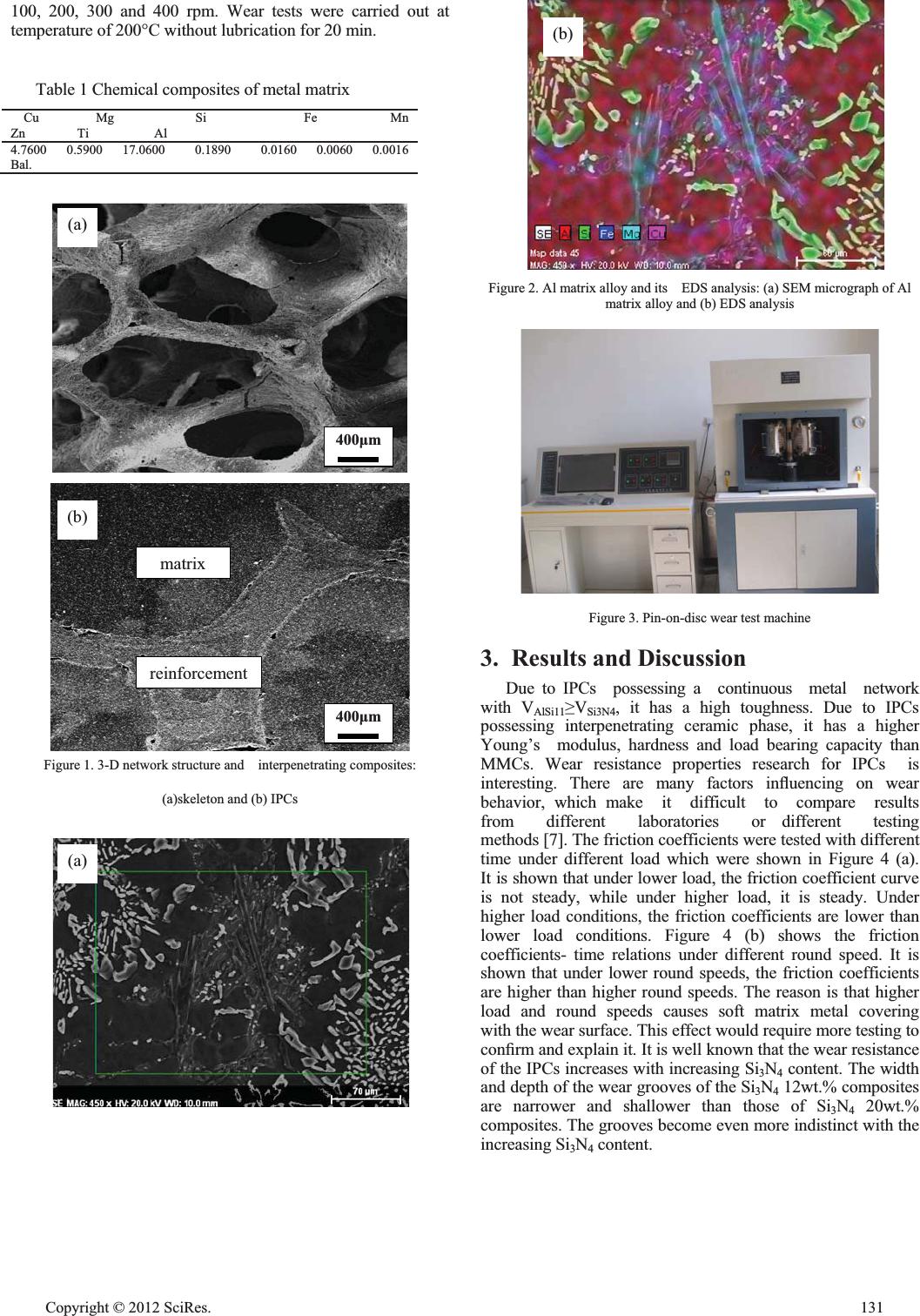 100, 200, 300 and 400 rpm. Wear tests were carried out at temperature of 200°C without lubrication for 20 min. Table 1 Chemical composites of metal matrix Cu Mg Si Fe Mn Zn Ti Al 4.7600 0.5900 17.0600 0.1890 0.0160 0.0060 0.0016 Bal. Figure 1. 3-D network structure and interpenetrating composites: (a)skeleton and (b) IPCs (b) Figure 2. Al matrix alloy and its EDS analysis: (a) SEM micrograph of Al matrix alloy and (b) EDS analysis Figure 3. Pin-on-disc wear test machine 3. Results and Discussion Due to IPCs possessing a continuous metal network with VAlSi11VSi3N4, it has a high toughness. Due to IPCs possessing interpenetrating ceramic phase, it has a higher Young’s modulus, hardness and load bearing capacity than MMCs. Wear resistance properties research for IPCs is interesting. There are many factors inÀuencing on wear behavior, which make it difficult to compare results from different laboratories or different testing methods [7]. The friction coefficients were tested with different time under different load which were shown in Figure 4 (a). It is shown that under lower load, the friction coefficient curve is not steady, while under higher load, it is steady. Under higher load conditions, the friction coefficients are lower than lower load conditions. Figure 4 (b) shows the friction coefficients- time relations under different round speed. It is shown that under lower round speeds, the friction coefficients are higher than higher round speeds. The reason is that higher load and round speeds causes soft matrix metal covering with the wear surface. This effect would require more testing to con¿rm and explain it. It is well known that the wear resistance of the IPCs increases with increasing Si3N4 content. The width and depth of the wear grooves of the Si3N4 12wt.% composites are narrower and shallower than those of Si3N4 20wt.% composites. The grooves become even more indistinct with the increasing Si3N4 content. 400ȝm 400ȝm (a) (b) matrix reinforcement (a) Cop y ri g ht © 2012 SciRes.131 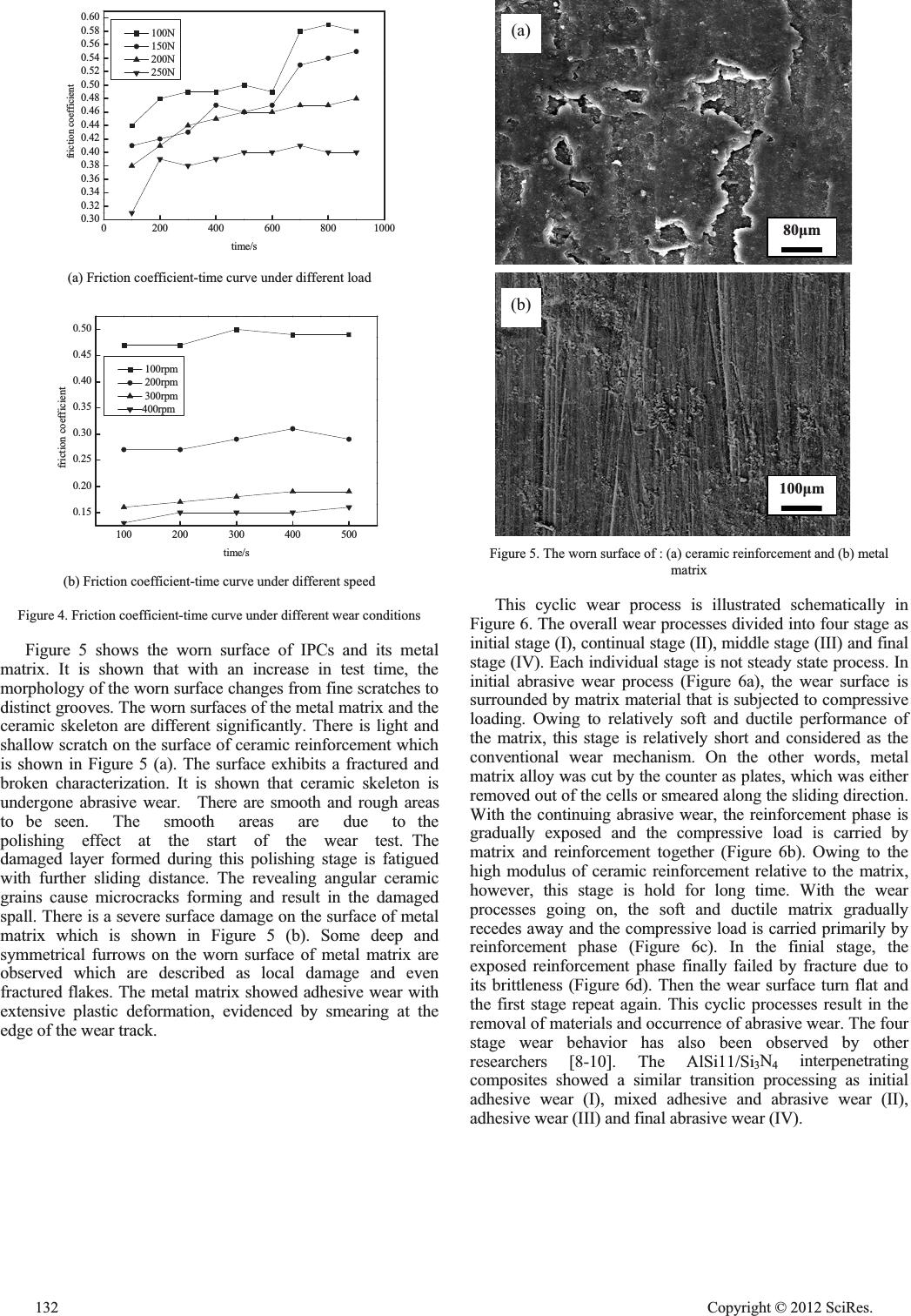 0200 400 600 8001000 0.30 0.32 0.34 0.36 0.38 0.40 0.42 0.44 0.46 0.48 0.50 0.52 0.54 0.56 0.58 0.60 friction coefficient time/s 100N 150N 200N 250N (a) Friction coefficient-time curve under different load 100 200 300 400 500 0.15 0.20 0.25 0.30 0.35 0.40 0.45 0.50 friction coefficient time/s 100rpm 200rpm 300rpm 400rpm (b) Friction coefficient-time curve under different speed Figure 4. Friction coefficient-time curve under different wear conditions Figure 5 shows the worn surface of IPCs and its metal matrix. It is shown that with an increase in test time, the morphology of the worn surface changes from fine scratches to distinct grooves. The worn surfaces of the metal matrix and the ceramic skeleton are different significantly. There is light and shallow scratch on the surface of ceramic reinforcement which is shown in Figure 5 (a). The surface exhibits a fractured and broken characterization. It is shown that ceramic skeleton is undergone abrasive wear. There are smooth and rough areas to be seen. The smooth areas are due to the polishing effect at the start of the wear test. The damaged layer formed during this polishing stage is fatigued with further sliding distance. The revealing angular ceramic grains cause microcracks forming and result in the damaged spall. There is a severe surface damage on the surface of metal matrix which is shown in Figure 5 (b). Some deep and symmetrical furrows on the worn surface of metal matrix are observed which are described as local damage and even fractured flakes. The metal matrix showed adhesive wear with extensive plastic deformation, evidenced by smearing at the edge of the wear track. Figure 5. The worn surface of : (a) ceramic reinforcement and (b) metal matrix This cyclic wear process is illustrated schematically in Figure 6. The overall wear processes divided into four stage as initial stage (I), continual stage (II), middle stage (III) and final stage (IV). Each individual stage is not steady state process. In initial abrasive wear process (Figure 6a), the wear surface is surrounded by matrix material that is subjected to compressive loading. Owing to relatively soft and ductile performance of the matrix, this stage is relatively short and considered as the conventional wear mechanism. On the other words, metal matrix alloy was cut by the counter as plates, which was either removed out of the cells or smeared along the sliding direction. With the continuing abrasive wear, the reinforcement phase is gradually exposed and the compressive load is carried by matrix and reinforcement together (Figure 6b). Owing to the high modulus of ceramic reinforcement relative to the matrix, however, this stage is hold for long time. With the wear processes going on, the soft and ductile matrix gradually recedes away and the compressive load is carried primarily by reinforcement phase (Figure 6c). In the finial stage, the exposed reinforcement phase finally failed by fracture due to its brittleness (Figure 6d). Then the wear surface turn flat and the first stage repeat again. This cyclic processes result in the removal of materials and occurrence of abrasive wear. The four stage wear behavior has also been observed by other researchers [8-10]. The AlSi11/Si3N4 interpenetrating composites showed a similar transition processing as initial adhesive wear (I), mixed adhesive and abrasive wear (II), adhesive wear (III) and final abrasive wear (IV). 80ȝm 100ȝm (a) (b) 132 Cop y ri g ht © 2012 SciRes. 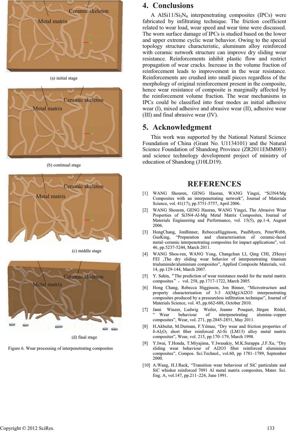 4. Conclusions A AlSi11/Si3N4 interpenetrating composites (IPCs) were fabricated by infiltrating technique. The friction coefficient related to wear load, wear speed and wear time were discussed. The worn surface damage of IPCs is studied based on the lower and upper extreme cyclic wear behavior. Owing to the special topology structure characteristic, aluminum alloy reinforced with ceramic network structure can improve dry sliding wear resistance. Reinforcements inhibit plastic flow and restrict propagation of wear cracks. Increase in the volume fraction of reinforcement leads to improvement in the wear resistance. Reinforcements are crushed into small pieces regardless of the morphology of original reinforcement present in the composite, hence wear resistance of composite is marginally affected by the reinforcement volume fraction. The wear mechanisms in IPCs could be classified into four modes as initial adhesive wear (I), mixed adhesive and abrasive wear (II), adhesive wear (III) and final abrasive wear (IV). Ceramic skeleton Metal matrix (a) initial stage Ceramic skeleton Metal matrix 5. Acknowledgment This work was supported by the National Natural Science Foundation of China (Grant No. U1134101) and the Natural Science Foundation of Shandong Province (ZR2011EMM003) and science technology development project of ministry of education of Shandong (J10LD19). (b) continual stage REFERENCES Ceramic skeleton [1]WANG Shouren, GENG Haoran, WANG Yingzi, “Si3N4/Mg Composites with an interpenetrating network”, Journal of Materials Science, vol. 41(17), pp.5751-5757, April 2006. Metal matrix [2]WANG Shouren, GENG Haoran, WANG Yingzi, The Abrasive Wear Properties of Si3N4-Al-Mg Metal Matrix Composites, Journal of Materials Engineering and Performance, vol. 15(5), pp.1-4, August 2006. [3]HongChang, JonBinner, RebeccaHigginson, PaulMyers, PeterWebb, GusKing, “Preparation and characterisation of ceramic-faced metal–ceramic interpenetrating composites for impact applications”, vol. 46, pp.5237-5244, March 2011. (c) middle stage [4]WANG Shou-ren, WANG Yong, Changchun LI, Qing CHI, ZHenyi FEI ,The dry sliding wear behavior of interpenetrating titanium trialuminide/aluminium composites”, Applied Composite Materials, vol. 14, pp.129-144, March 2007. Ceramic skeleton [5]Y. Sahin,ĀThe prediction of wear resistance model for the metal matrix compositesāˈvol. 258, pp.1717-1722, March 2005. Metal matrix [6]Hong Chang, Rebecca Higginson, Jon Binner, “Microstructure and property characterisation of 3-3 Al(Mg)/Al2O3 interpenetrating composites produced by a pressureless in¿ltration technique”, Journal of Materials Science, vol. 45, pp.662-688, October 2010. [7]Jami Winzer, Ludwig Weiler, Jeanne Pouquet, Jürgen Rödel, “ Wear behaviour of interpenetrating alumina–copper composites”, Wear, vol. 271, pp.2845-2851, May 2011. [8]H.Akbulut, M.Durman, F.YÕlmaz, “Dry wear and friction properties of į-Al2O3 short ¿ber reinforced Al-Si (LM13) alloy metal matrix composites”, Wear, vol. 215, pp.170–179, March 1998. (d) final stage [9]Y.Iwai, T.Honda, T.Miyajima, Y.Iwasakiy, M.K.Surappa ,J.F.Xu, “Dry sliding wear behaviour of Al2O3 ¿ber reinforced aluminium composites”, Compos. Sci.Technol., vol.60, pp 1781–1789, September 2000. Figure 6. Wear processing of interpenetrating composites [10]A.Wang, H.J.Rack, “Transition wear behaviour of SiC particulate and SiC whisker reinforced 7091 Al metal matrix composites, Mater. Sci. Eng. A, vol.147, pp.211–224, June 1991. Cop y ri g ht © 2012 SciRes.133 |