Paper Menu >>
Journal Menu >>
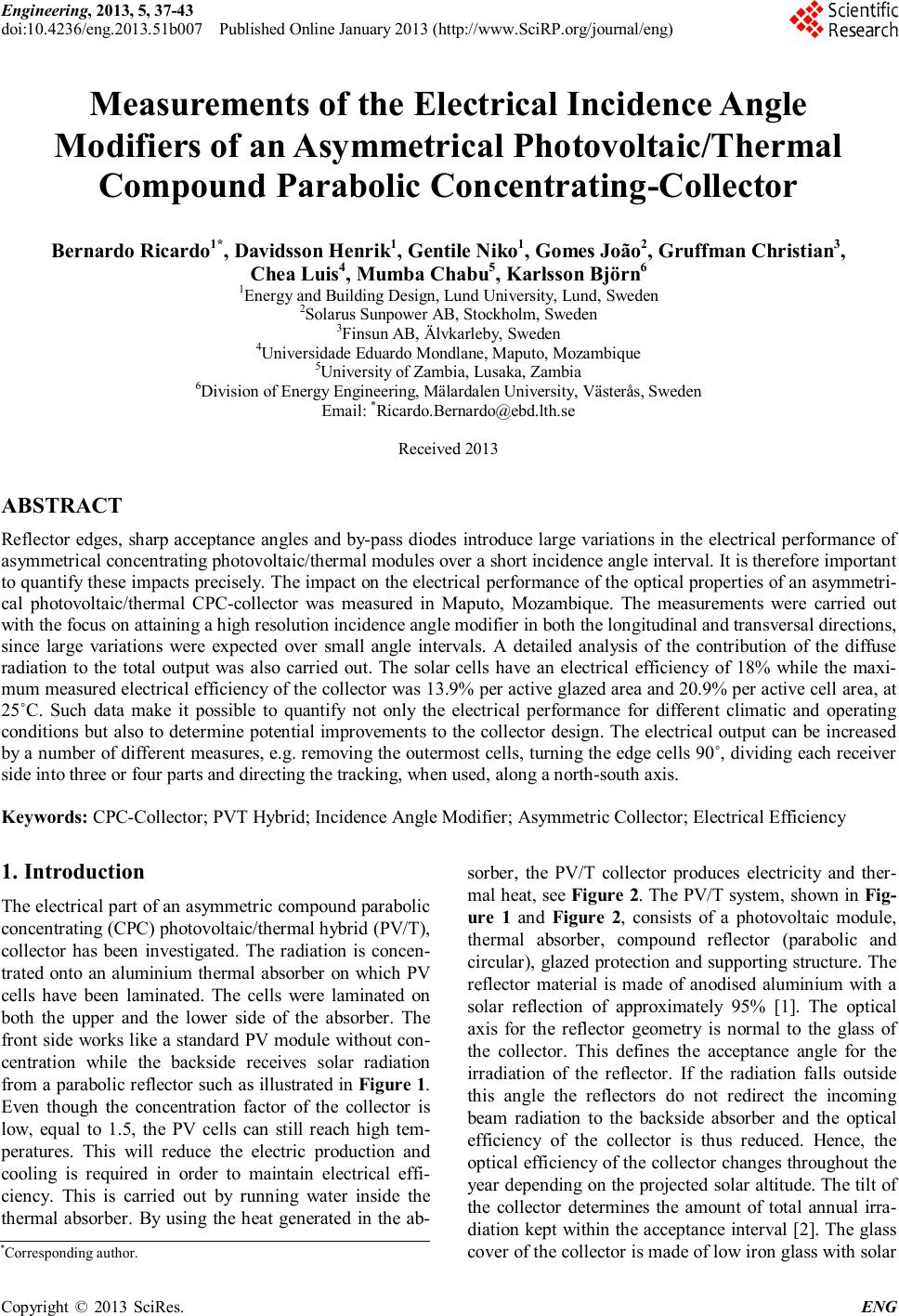 Engineering, 2013, 5, 37-43 doi:10.4236/eng.2013.51b007 Published Online January 2013 (http://www.SciRP.org/journal/eng) Copyright © 2013 SciRes. ENG Measurements of the Electrical Incidence Angle Modifiers of an Asymmetrical Photovoltaic/Thermal Compound Parabolic Concentrating-Collector Bernardo Ricardo1*, Davidsson Henrik1, Gentile Niko1, Gomes João2, Gruffman Christian3, Chea Luis4, Mumba Chabu5, Karlsson Björn6 1Energy and Building Design, Lund University, Lund, Sweden 2Solarus Sunpower AB, Stockholm, Sweden 3Finsun AB, Älvkarleby, Sweden 4Universidade Eduardo Mondlane, Maputo, Mozambique 5University of Zambia, Lusaka, Zambia 6Division of Energy Engineering, Mälardalen University, Västerås, Sweden Email: *Ricardo.Bernardo@ebd.lth.se Received 2013 ABSTRACT Reflector edges, sharp acceptance angles and by-pass diodes introduce large variations in the electrical performance of asymmetrical concentrating photovoltaic/thermal modules over a short incidence angle interval. It is therefore important to quantify these impacts precisely. The impact on the electrical performance of the optical properties of an asymmetri- cal photovoltaic/thermal CPC-collector was measured in Maputo, Mozambique. The measurements were carried out with the focus on attaining a high resolution incidence angle modifier in both the longitudinal and transversal directions, since large variations were expected over small angle intervals. A detailed analysis of the contribution of the diffuse radiation to the total output was also carried out. The solar cells have an electrical efficiency of 18% while the maxi- mum measured electrical efficiency of the collector was 13.9% per active glazed area and 20.9% per active cell area, at 25˚C. Such data make it possible to quantify not only the electrical performance for different climatic and operating conditions but also to determine potential improvements to the collector design. The electrical output can be increased by a number of different measures, e.g. removing the outermost cells, turning the edge cells 90˚, dividing each receiver side into three or four parts and directing the tracking, when used, along a north-south axis. Keywords: CPC-Collector; PVT Hybrid; Incidence Angle Modifier; Asymmetric Collector; Electrical Efficiency 1. Introduction The electrical part of an asymmetric compound parabolic concentrating (CPC) photovoltaic/thermal hybrid (PV/T), collector has been investigated. The radiation is concen- trated onto an aluminium thermal absorber on which PV cells have been laminated. The cells were laminated on both the upper and the lower side of the absorber. The front side works like a standard PV module without con- centration while the backside receives solar radiation from a parabolic reflector such as illustrated in Figure 1. Even though the concentration factor of the collector is low, equal to 1.5, the PV cells can still reach high tem- peratures. This will reduce the electric production and cooling is required in order to maintain electrical effi- ciency. This is carried out by running water inside the thermal absorber. By using the heat generated in the ab- sorber, the PV/T collector produces electricity and ther- mal heat, see Figure 2. The PV/T system, shown in Fig- ure 1 and Figure 2, consists of a photovoltaic module, thermal absorber, compound reflector (parabolic and circular), glazed protection and supporting structure. The reflector material is made of anodised aluminium with a solar reflection of approximately 95% [1]. The optical axis for the reflector geometry is normal to the glass of the collector. This defines the acceptance angle for the irradiation of the reflector. If the radiation falls outside this angle the reflectors do not redirect the incoming beam radiation to the backside absorber and the optical efficiency of the collector is thus reduced. Hence, the optical efficiency of the collector changes throughout the year depending on the projected solar altitude. The tilt of the collector determines the amount of total annual irra- diation kept within the acceptance interval [2]. The glass cover of the collector is made of low iron glass with solar *Corresponding author. 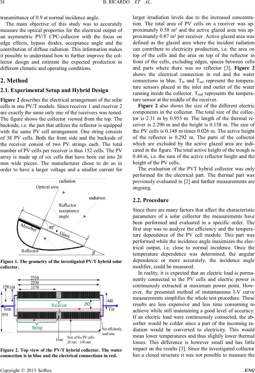 B. RICARDO ET AL. Copyright © 2013 SciRes. ENG 38 transmittance of 0.9 at normal incidence angle. The main objective of this study was to accurately measure the optical properties for the electrical output of an asymmetric PV/T CPC-collector with the focus on edge effects, bypass diodes, acceptance angle and the contribution of diffuse radiation. This information makes it possible to understand how to further improve the col- lector design and estimate the expected production in different climatic and operating conditions. 2. Method 2.1. Experimental Setup and Hybrid Design Figure 2 describes the electrical arrangement of the solar cells in one PV/T module. Since receiver 1 and receiver 2 are exactly the same only one of the receivers was tested. The figure shows the collector viewed from the top. The backside, i.e. the part that utilizes the reflector is equipped with the same PV cell arrangement. One string consists of 38 PV cells. Both the front side and the backside of the receiver consist of two PV strings each. The total number of PV cells per receiver is thus 152 cells. The PV array is made up of six cells that have been cut into 26 mm wide pieces. The manufacturer chose to do so in order to have a larger voltage and a smaller current for Figure 1. The geometry of the investigated PV/T hybrid solar collector. Figure 2. Top view of the PV/T hybrid collector. The water connection is in blue and the electrical connections in red. larger irradiation levels due to the increased concentra- tion. The total area of PV cells on a receiver was ap- proximately 0.58 m² and the active glazed area was ap- proximately 0.87 m² per receiver. Active glazed area was defined as the glazed area where the incident radiation can contribute to electricity production, i.e. the area on top of the cells and the area on top of the reflector in front of the cells, excluding edges, spaces between cells and parts where there was no reflector [3]. Figure 2 shows the electrical connection in red and the water connections in blue. Tin and Tout represent the tempera- ture sensors placed at the inlet and outlet of the water running inside the collector. Tmid represents the tempera- ture sensor at the middle of the receiver. Figure 2 also shows the size of the different electric components in the collector. The total size of the collec- tor is 2.31 m by 0.955 m. The length of the thermal re- ceiver is 2.290 m and the height is 0.158 m. The size of the PV cells is 0.148 m times 0.026 m. The active height of the reflector is 0.292 m. The parts of the collector which are excluded by the active glazed area are indi- cated in the figure. The total active height of the trough is 0.44 m, i.e. the sum of the active reflector height and the height of the PV cells. The evaluation of the PVT hybrid collector was only performed for the electrical part. The thermal part was previously evaluated in [2] and further measurements are ongoing. 2.2. Procedure Since there are many factors that affect the characteristic parameters of a solar collector the measurements have been performed and evaluated in a specific order. The first step was to analyze the efficiency and the tempera- ture dependence of the PV cell module. This part was performed while the incidence angle maximizes the elec- trical output, i.e. close to normal incidence. Once the temperature dependence was determined, the angular dependence or more accurately, the incidence angle modifier, could be measured. In reality, it is expected that an electric load is perma- nently connected to the PV cells and electric power is continuously extracted at maximum power point. How- ever, the presented method of instantaneous I-V curve measurements simplifies the whole test procedure. These results are less expensive and less time consuming to achieve while still maintaining a good level of accuracy. If an electric load were continuously connected, the ab- sorber would be colder since a part of the incoming ra- diation would be converted to electricity. This would mean lower temperatures and thus slightly lower thermal losses. This difference is however small and has little impact on the results [3]. Since the investigated collector has a closed structure it was not possible to measure the 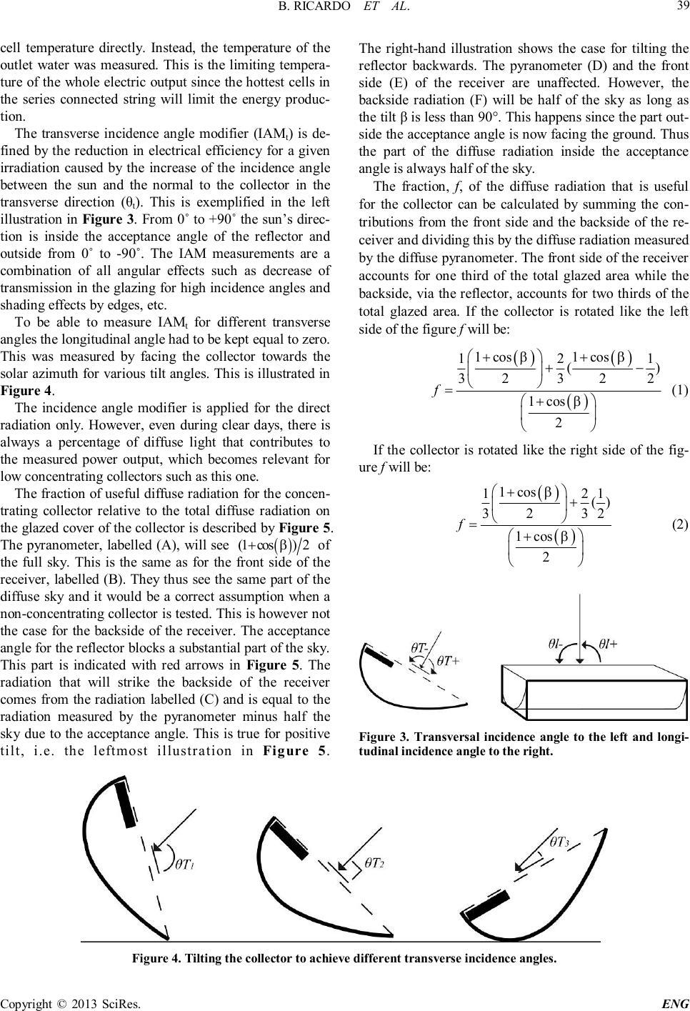 B. RICARDO ET AL. Copyright © 2013 SciRes. ENG 39 cell temperature directly. Instead, the temperature of the outlet water was measured. This is the limiting tempera- ture of the whole electric output since the hottest cells in the series connected string will limit the energy produc- tion. The transverse incidence angle modifier (IAMt) is de- fined by the reduction in electrical efficiency for a given irradiation caused by the increase of the incidence angle between the sun and the normal to the collector in the transverse direction (θ t ). This is exemplified in the left illustration in Figure 3. From 0˚ to +90˚ the sun’s direc- tion is inside the acceptance angle of the reflector and outside from 0˚ to -90˚. The IAM measurements are a combination of all angular effects such as decrease of transmission in the glazing for high incidence angles and shading effects by edges, etc. To be able to measure IAMt for different transverse angles the longitudinal angle had to be kept equal to zero. This was measured by facing the collector towards the solar azimuth for various tilt angles. This is illustrated in Figure 4. The incidence angle modifier is applied for the direct radiation only. However, even during clear days, there is always a percentage of diffuse light that contributes to the measured power output, which becomes relevant for low concentrating collectors such as this one. The fraction of useful diffuse radiation for the concen- trating collector relative to the total diffuse radiation on the glazed cover of the collector is described by Figure 5. The pyranometer, labelled (A), will see ( ) (1cos)2 β+ of the full sky. This is the same as for the front side of the receiver, labelled (B). They thus see the same part of the diffuse sky and it would be a correct assumption when a non-concentrating collector is tested. This is however not the case for the backside of the receiver. The acceptance angle for the reflector blocks a substantial part of the sky. This part is indicated with red arrows in Figure 5. The radiation that will strike the backside of the receiver comes from the radiation labelled (C) and is equal to the radiation measured by the pyranometer minus half the sky due to the acceptance angle. This is true for positive tilt, i.e. the leftmost illustration in Figure 5. The right-hand illustration shows the case for tilting the reflector backwards. The pyranometer (D) and the front side (E) of the receiver are unaffected. However, the backside radiation (F) will be half of the sky as long as the tilt β is less than 90°. This happens since the part out- side the acceptance angle is now facing the ground. Thus the part of the diffuse radiation inside the acceptance angle is always half of the sky. The fraction, f, of the diffuse radiation that is useful for the collector can be calculated by summing the con- tributions from the front side and the backside of the re- ceiver and dividing this by the diffuse radiation measured by the diffuse pyranometer. The front side of the receiver accounts for one third of the total glazed area while the backside, via the reflector, accounts for two thirds of the total glazed area. If the collector is rotated like the left side of the figure f will be: ( ) ( ) ( ) 1cos1cos 121 () 32322 1cos 2 f ββ β ++ +− =+ (1) If the collector is rotated like the right side of the fig- ure f will be: ( ) ( ) 1cos 121 () 3232 1cos 2 f β β + + = + (2) Figure 3. Transversal incidence angle to the left and longi- tudinal incidence angle to the right. Figure 4. Tilting the collector to achieve different transverse incidence angles. 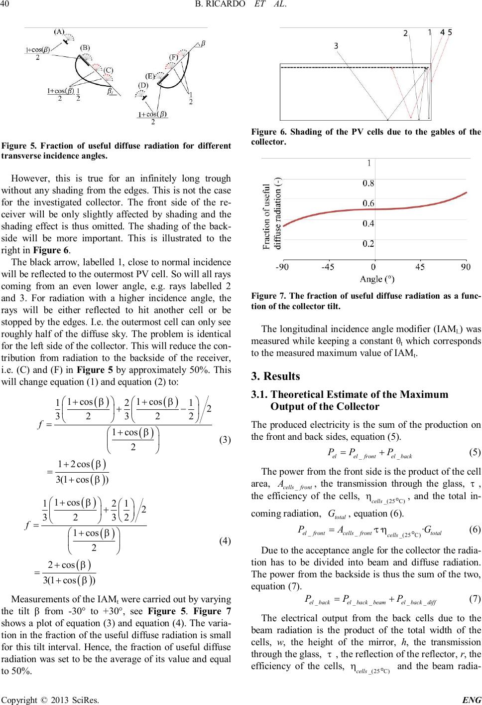 B. RICARDO ET AL. Copyright © 2013 SciRes. ENG 40 Figure 5. Fraction of useful diffuse radiation for different transverse incidence angles. However, this is true for an infinitely long trough without any shading from the edges. This is not the case for the investigated collector. The front side of the re- ceiver will be only slightly affected by shading and the shading effect is thus omitted. The shading of the back- side will be more important. This is illustrated to the right in Figure 6. The black arrow, labelled 1, close to normal incidence will be reflected to the outermost PV cell. So will all rays coming from an even lower angle, e.g. rays labelled 2 and 3. For radiation with a higher incidence angle, the rays will be either reflected to hit another cell or be stopped by the edges. I.e. the outermost cell can only see roughly half of the diffuse sky. The problem is identical for the left side of the collector. This will reduce the con- tribution from radiation to the backside of the receiver, i.e. (C) and (F) in Figure 5 by approximately 50%. This will change equation (1) and equation (2) to: ( ) ( ) ( ) ( ) ( ) 1cos1cos 121 2 32322 1cos 2 12cos 3(1cos) f ββ β β β ++ +− =+ + = + (3) ( ) ( ) ( ) ( ) 1cos 121 2 3232 1cos 2 2cos 3(1cos) f β β β β + + = + + = + (4) Measurements of the IAMt were carried out by varying the tilt β from -30° to +30°, see Figure 5. Figure 7 shows a plot of equation (3) and equation (4). The varia- tion in the fraction of the useful diffuse radiation is small for this tilt interval. Hence, the fraction of useful diffuse radiation was set to be the average of its value and equal to 50%. Figure 6. Shading of the PV cells due to the gables of the collector. Figure 7. The fraction of useful diffuse radiation as a func- tion of the collector tilt. The longitudinal incidence angle modifier (IAMl.) was measured while keeping a constant θt which corresponds to the measured maximum value of IAMt. 3. Results 3.1. Theoretical Estimate of the Maximum Output of the Collector The produced electricity is the sum of the production on the front and back sides, equation (5). __ elelfrontelback PPP=+ (5) The power from the front side is the product of the cell area, _ cellsfront A, the transmission through the glass, τ , the efficiency of the cells, _(25C) cells ηo, and the total in- coming radiation, total G, equation (6). __ _(25C) ·· · elfrontcellsfronttotal cells PAGτη=o (6) Due to the acceptance angle for the collector the radia- tion has to be divided into beam and diffuse radiation. The power from the backside is thus the sum of the two, equation (7). _____ elbackelbackbeamelbackdiff PPP=+ (7) The electrical output from the back cells due to the beam radiation is the product of the total width of the cells, w, the height of the mirror, h, the transmission through the glass, τ , the reflection of the reflector, r, the efficiency of the cells, _(25C) cells ηo and the beam radia- 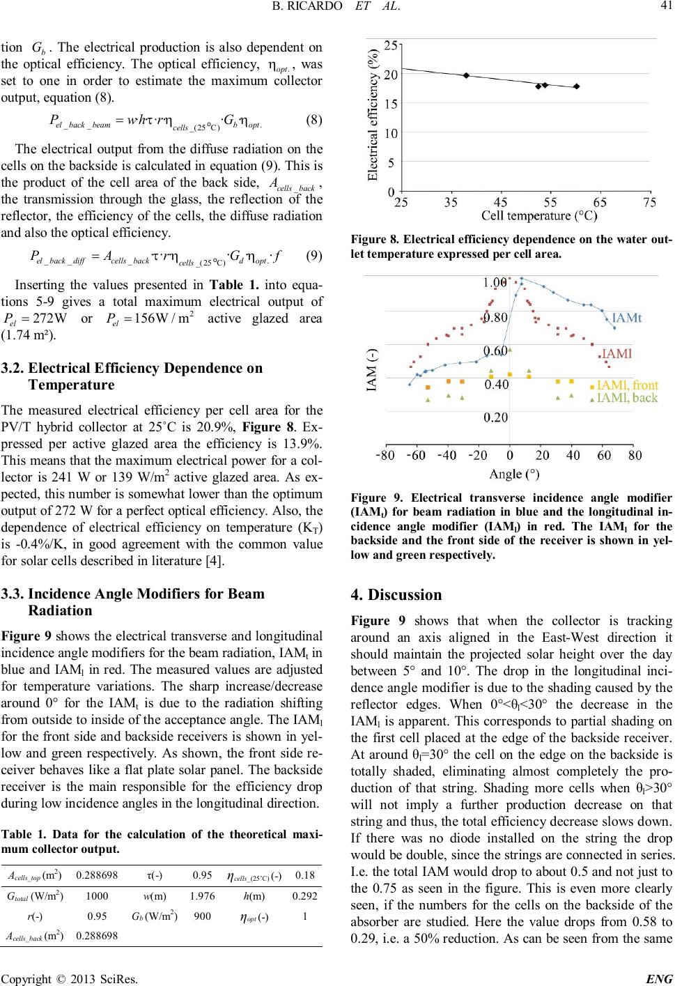 B. RICARDO ET AL. Copyright © 2013 SciRes. ENG 41 tion b G . The electrical production is also dependent on the optical efficiency. The optical efficiency, . opt η , was set to one in order to estimate the maximum collector output, equation (8). __. _(25C) ···· · · elbackbeambopt cells PwhrG τηη =o (8) The electrical output from the diffuse radiation on the cells on the backside is calculated in equation (9). This is the product of the cell area of the back side, _ cellsback A, the transmission through the glass, the reflection of the reflector, the efficiency of the cells, the diffuse radiation and also the optical efficiency. ___. _(25C) ···· · · elbackdiffcellsbackdopt cells PArGf τηη=o (9) Inserting the values presented in Table 1. into equa- tions 5-9 gives a total maximum electrical output of 272W el P= or 2 156W/m el P= active glazed area (1.74 m²). 3.2. Electrical Efficiency Dependence on Temperature The measured electrical efficiency per cell area for the PV/T hybrid collector at 25˚C is 20.9%, Figure 8. Ex- pressed per active glazed area the efficiency is 13.9%. This means that the maximum electrical power for a col- lector is 241 W or 139 W/m2 active glazed area. As ex- pected, this number is somewhat lower than the optimum output of 272 W for a perfect optical efficiency. Also, the dependence of electrical efficiency on temperature (KT) is -0.4%/K, in good agreement with the common value for solar cells described in literature [4]. 3.3. Incidence Angle Modifiers for Beam Radiation Figure 9 shows the electrical transverse and longitudinal incidence angle modifiers for the beam radiation, IAMt in blue and IAMl in red. The measured values are adjusted for temperature variations. The sharp increase/decrease around 0° for the IAMt is due to the radiation shifting from outside to inside of the acceptance angle. The IAMl for the front side and backside receivers is shown in yel- low and green respectively. As shown, the front side re- ceiver behaves like a flat plate solar panel. The backside receiver is the main responsible for the efficiency drop during low incidence angles in the longitudinal direction. Table 1. Data for the calculation of the theoretical maxi- mum collector output. Acells_top (m2) 0.288698 τ(-) 0.95 ηcells_(25˚C) (-) 0.18 Gtotal (W/m2) 1000 w(m) 1.976 h(m) 0.292 r(-) 0.95 Gb (W/m2) 900 ηopt (-) 1 Acells_back (m2) 0.288698 Figure 8. Electrical efficiency dependence on the water out- let temperature expressed per cell area. Figure 9. Electrical transverse incidence angle modifier (IAMt) for beam radiation in blue and the longitudinal in- cidence angle modifier (IAMl) in red. The IAMl for the backside and the front side of the receiver is shown in yel- low and green respectively. 4. Discussion Figure 9 shows that when the collector is tracking around an axis aligned in the East-West direction it should maintain the projected solar height over the day between 5° and 10°. The drop in the longitudinal inci- dence angle modifier is due to the shading caused by the reflector edges. When 0°<θ l <30° the decrease in the IAMl is apparent. This corresponds to partial shading on the first cell placed at the edge of the backside receiver. At around θl=30° the cell on the edge on the backside is totally shaded, eliminating almost completely the pro- duction of that string. Shading more cells when θl>30° will not imply a further production decrease on that string and thus, the total efficiency decrease slows down. If there was no diode installed on the string the drop would be double, since the strings are connected in series. I.e. the total IAM would drop to about 0.5 and not just to the 0.75 as seen in the figure. This is even more clearly seen, if the numbers for the cells on the backside of the absorber are studied. Here the value drops from 0.58 to 0.29, i.e. a 50% reduction. As can be seen from the same 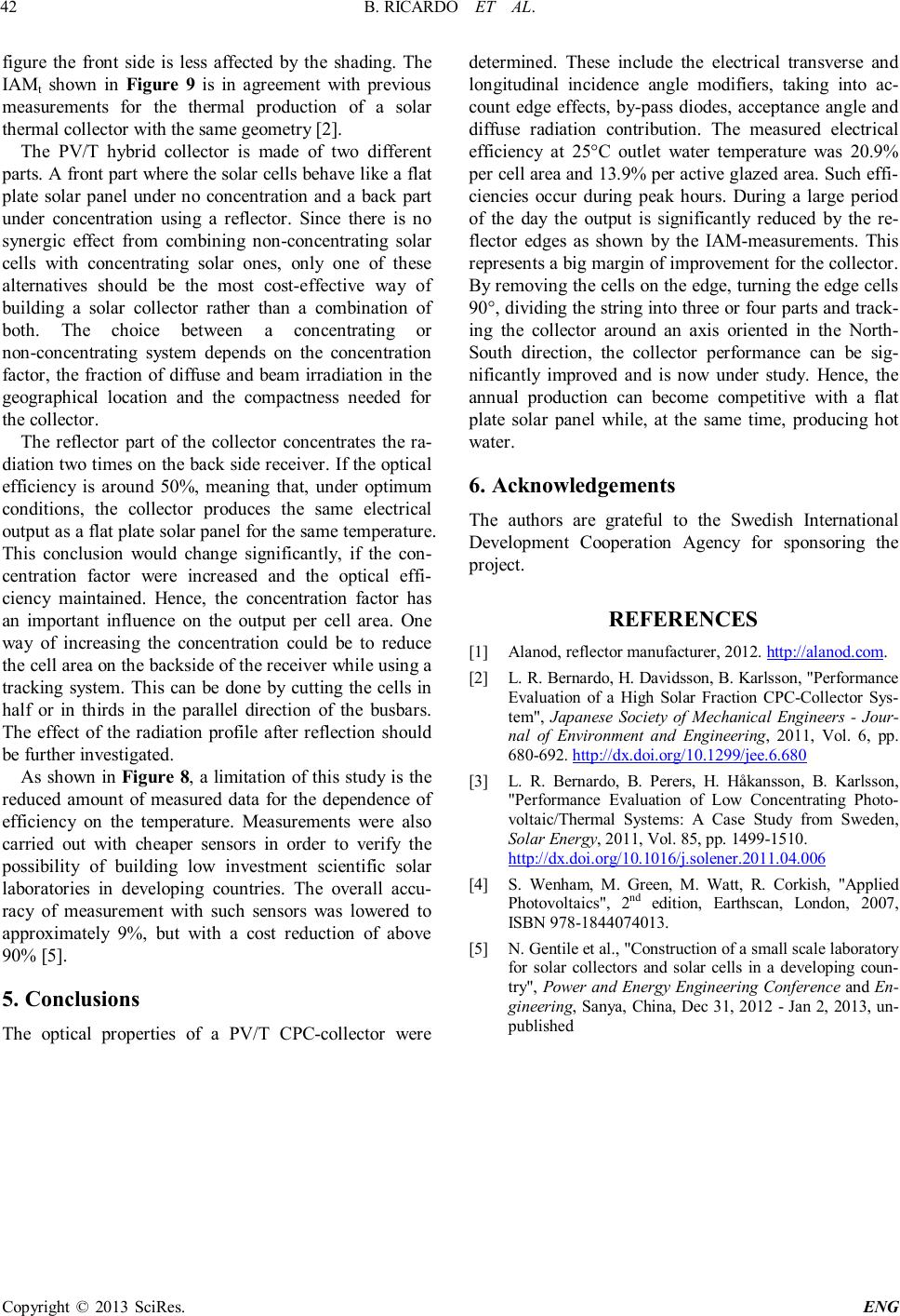 B. RICARDO ET AL. Copyright © 2013 SciRes. ENG 42 figure the front side is less affected by the shading. The IAMt shown in Figure 9 is in agreement with previous measurements for the thermal production of a solar thermal collector with the same geometry [2]. The PV/T hybrid collector is made of two different parts. A front part where the solar cells behave like a flat plate solar panel under no concentration and a back part under concentration using a reflector. Since there is no synergic effect from combining non-concentrating solar cells with concentrating solar ones, only one of these alternatives should be the most cost-effective way of building a solar collector rather than a combination of both. The choice between a concentrating or non-concentrating system depends on the concentration factor, the fraction of diffuse and beam irradiation in the geographical location and the compactness needed for the collector. The reflector part of the collector concentrates the ra- diation two times on the back side receiver. If the optical efficiency is around 50%, meaning that, under optimum conditions, the collector produces the same electrical output as a flat plate solar panel for the same temperature. This conclusion would change significantly, if the con- centration factor were increased and the optical effi- ciency maintained. Hence, the concentration factor has an important influence on the output per cell area. One way of increasing the concentration could be to reduce the cell area on the backside of the receiver while using a tracking system. This can be done by cutting the cells in half or in thirds in the parallel direction of the busbars. The effect of the radiation profile after reflection should be further investigated. As shown in Figure 8, a limitation of this study is the reduced amount of measured data for the dependence of efficiency on the temperature. Measurements were also carried out with cheaper sensors in order to verify the possibility of building low investment scientific solar laboratories in developing countries. The overall accu- racy of measurement with such sensors was lowered to approximately 9%, but with a cost reduction of above 90% [5]. 5. Conclusions The optical properties of a PV/T CPC-collector were determined. These include the electrical transverse and longitudinal incidence angle modifiers, taking into ac- count edge effects, by-pass diodes, acceptance angle and diffuse radiation contribution. The measured electrical efficiency at 25°C outlet water temperature was 20.9% per cell area and 13.9% per active glazed area. Such effi- ciencies occur during peak hours. During a large period of the day the output is significantly reduced by the re- flector edges as shown by the IAM-measurements. This represents a big margin of improvement for the collector. By removing the cells on the edge, turning the edge cells 90°, dividing the string into three or four parts and track- ing the collector around an axis oriented in the North- South direction, the collector performance can be sig- nificantly improved and is now under study. Hence, the annual production can become competitive with a flat plate solar panel while, at the same time, producing hot water. 6. Acknowledgements The authors are grateful to the Swedish International Development Cooperation Agency for sponsoring the project. REFERENCES [1] Alanod, reflector manufacturer, 2012. http://alanod.com. [2] L. R. Bernardo, H. Davidsson, B. Karlsson, "Performance Evaluation of a High Solar Fraction CPC-Collector Sys- tem", Japanese Society of Mechanical Engineers - Jour- nal of Environment and Engineering, 2011, Vol. 6, pp. 680-692. http://dx.doi.org/10.1299/jee.6.680 [3] L. R. Bernardo, B. Perers, H. Håkansson, B. Karlsson, "Performance Evaluation of Low Concentrating Photo- voltaic/Thermal Systems: A Case Study from Sweden, Solar Energy, 2011, Vol. 85, pp. 1499-1510. http://dx.doi.org/10.1016/j.solener.2011.04.006 [4] S. Wenham, M. Green, M. Watt, R. Corkish, "Applied Photovoltaics", 2 nd edition, Earthscan, London, 2007, ISBN 978-1844074013. [5] N. Gentile et al., "Construction of a small scale laboratory for solar collectors and solar cells in a developing coun- try", Power and Energy Engineering Conference and En- gineering, Sanya, China, Dec 31, 2012 - Jan 2, 2013, un- published  B. RICARDO ET AL. Copyright © 2013 SciRes. ENG 43 Nomenclature Pel Hybrid electric power (W) Pel_front Hybrid electric power from front side receiver (W) Pel_back Hybrid electric power from backside receiver (W) Pel_back_beam Hybrid electric power from backside receiver due to beam radiation (W) Pel_back_diff Hybrid electric power from backside receiver due to diffuse radiation (W) Gtotal Total irradiance (W/m²) Gb Beam Irradiance (W/m²) Gd Diffuse Irradiance (W/m²) Tin Inlet water temperature (°C) Tout Outlet water temperature (°C) Tmid Middle water temperaure (°C) Acells_front Cell area of the front side receiver (m²) Acells_back Cell area of the backside receiver (m²) β Collector tilt from horizontal (°) f Useful fraction of diffuse radiation ) -( τ Transmittance coefficient of glass (-) r Reflectance coefficient of the reflector (-) w Total width of the cells (m2) h Height of the reflector (m2) C Concentration factor of the collector (-) ηcells_(25°C) Cell efficiency at 25°C (-) ηopt Optical efficiency (-) KT Electrical efficiency temperature dependence (%/ °C) θ Angle of incidence onto collector (°) θt Transverse angle of incidence onto collector (°) θl Longitudinal angle of incidence onto collector (°) IAMl Electrical longitudinal incidence angle modifier (-) IAMt Electrical transverse incidence angle modifier (-) |