Paper Menu >>
Journal Menu >>
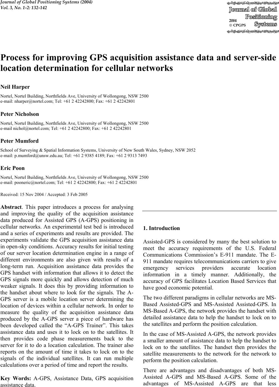 Journal of Global Positioning Systems (2004) Vol. 3, No. 1-2: 132-142 Process for improving GPS acquisition assistance data and server-side location determination for cellular networks Neil Harper Nortel, Nortel Building, Northfields Ave, University of Wollongong, NSW 2500 e-mail: nharper@nortel.com; Tel: +61 2 42242800; Fax: +61 2 42242801 Peter Nicholson Nortel, Nortel Building, Northfields Ave, University of Wollongong, NSW 2500 e-mail nichol@nortel.com; Tel: +61 2 42242800; Fax: +61 2 42242801 Peter Mumford School of Surveying & Spatial Information Systems, University of New South Wales, Sydney, NSW 2052 e-mail: p.mumford@unsw.edu.au; Tel: +61 2 9385 4189; Fax: +61 2 9313 7493 Eric Poon Nortel, Nortel Building, Northfields Ave, University of Wollongong, NSW 2500 e-mail: pooneric@nortel.com; Tel: +61 2 42242800; Fax: +61 2 42242801 Received: 15 Nov 2004 / Accepted: 3 Feb 2005 Abstract. This paper introduces a process for analysing and improving the quality of the acquisition assistance data produced for Assisted GPS (A-GPS) positioning in cellular networks. An experimental test bed is introduced and a series of experiments and results are provided. The experiments validate the GPS acquisition assistance data in open-sky conditions. Accuracy results for initial testing of our server location determination engine in a range of different environments are also given with results of a long-term run. Acquisition assistance data provides the GPS handset with information that allows it to detect the GPS signals more quickly and allows detection of much weaker signals. It does this by providing information to the handset about where to look for the signals. The A- GPS server is a mobile location server determining the location of devices within a cellular network. In order to measure the quality of the acquisition assistance data produced by the A-GPS server a piece of hardware has been developed called the “A-GPS Trainer”. This takes assistance data and uses it to lock on to the satellites. It then provides code phase measurements back to the server for it to do a location calculation. The trainer also reports on the amount of time it takes to lock on to the signals of the individual satellites. It can run multiple calculations over a period of time and report the results. Key Words: A-GPS, Assistance Data, GPS acquisition assistance data. 1. Introduction Assisted-GPS is considered by many the best solution to meet the accuracy requirements of the U.S. Federal Communications Commission’s E-911 mandate. The E- 911 mandate requires telecommunications carriers to give emergency services providers accurate location information in a timely manner. Additionally, the accuracy of GPS facilitates Location Based Services that have good economic potential. The two different paradigms in cellular networks are MS- Based Assisted-GPS and MS-Assisted Assisted-GPS. In MS-Based A-GPS, the network provides the handset with detailed assistance data to help the handset to lock on to the satellites and perform the position calculation. In the case of MS-Assisted A-GPS, the network provides a smaller amount of assistance data to help the handset to lock on to the satellites. The handset then provides the satellite measurements to the network for the network to perform the position calculation. There are advantages and disadvantages of both MS- Assisted A-GPS and MS-Based A-GPS. Some of the advantages of MS-Assisted A-GPS are that less  Harper et al: Process for improving GPS acquisition assistance data and server-side location determination 133 information is transmitted over the air interface, and there is potential on the server to use other information such as network timing information from base stations or a Digital Elevation Model. Another benefit is that the position calculation is centralised so that any software problem can be fixed in one place on the server instead of millions of customer handsets. GPS acquisition assistance data is used by an MS- Assisted A-GPS handset to lock on to satellite signals. This paper describes a test bed and a process for tuning the server-side algorithm which produces the acquisition assistance data. In an emergency situation, the time it takes to lock on to the satellites is very important and in this paper the time to lock on to the satellites in open sky conditions from a cold start is optimised. The results show that acquisition assistance data speeds up the acquisition by about 200 times with our hardware. A measure called the ‘acquisition assistance usefulness factor’ is introduced. This factor is the ratio of the relative speed of the GPS fixes scaled by the proportion of the satellites in view that the device locks on to. It defines how good the acquisition assistance data is for a particular GPS fix. The other major part of an MS-Assisted A-GPS solution is the position calculation function. In this paper some results of testing at the University of New South Wales (UNSW) and the results of a long-term run (18 months) are given. 2. Background Nortel Networks manufactures various 3GPP-compliant cellular network elements. These elements include Serving Mobile Location Centers (SMLC), Radio Network Controllers (RNC) and Standalone A-GPS SMLCs (SAS). These elements generate GPS acquisition assistance data for cellular phones with embedded A-GPS capability. The GPS assistance data speeds up acquisition of GPS signals and increases GPS yield in weak signal environments. It was necessary to develop a process and a test environment that allowed the effectiveness of the supplied GPS assistance data to be measured. The ultimate measure of the value of the assistance data is to make empirical observations on the impact to sensitivity and time-to-fix with an A-GPS receiver. The testing process and environment developed facilitates many such observations being made, ensuring a valid set of statistical measurements. The test environment provides a means of measuring the effects of optimising the assistance data. By measuring the results of changes to the supplied assistance data, a validation can be performed to ensure that the data provides optimal results in practice. In addition, the test environment provides a practical regression test suite to ensure future versions of the assistance data calculation software produce correct assistance data. Assistance data helps to significantly reduce the search space required by the GPS enabled handset (Zhao 2002, Djuknic and Richton 2001). Fast, accurate fixes can be made using a combination of good assistance data and high sensitivity receivers (van Diggelen and Abraham 2001, and Heinrich et al 2004). Much of the literature concentrates on improvements to the handset. This paper is focused on improvements that can be made on the server. 3. GPS acquisition assistance data The cellular network can provide assistance data to the A- GPS cellular handset through the air when it is in contact with a base station. Assistance data types that can be sent to the handset includes the ephemeris, reference time, ionosphere model, UTC model, real time integrity and acquisition assistance. The format of the GPS acquisition assistance data is defined by the relevant standards body; the specifics of the encoding and field ranges depend on the access technology. The protocol for the GSM system for example is defined in 3GPP TS 04.21 and is referred to as RRLP (Radio Resource LCS protocol). Other protocols include Positioning Calculation Application Part (PCAP) for UMTS networks (between the SAS and the RNC) and Position Determination Service Standard for Dual Mode Spread Spectrum Systems (PDDM) for CDMA networks. A high-level diagram of an SMLC network is shown in Fig. 1. In this scenario, the SMLC receives a request for assistance data for a particular handset. The request effectively includes the initial location estimate and the uncertainty of the estimate, which is based on the size of the serving cell. This initial location estimate and the uncertainty are used to calculate the acquisition assistance data using information from the Wide Area Reference Network (WARN). This acquisition assistance data is used to populate the message that is sent back to the network and on to the handset. The fields that the server provides are summarised in Tab. 1. They are named similarly and have similar ranges across the different network access technologies  134 Journal of Global Positioning Systems Fig. 1. A-GPS in a cellular network Tab. 1. The fields for GPS Acquisition assistance data Field Approximate Range Notes GPS Time 0 to 604800.0 The GPS time of week in seconds at which the assistance data is relevant Satellite Information The following fields appear for each satellite in the message: Satellite ID The satellite ID Doppler -5120 to 5117.5 Hz The predicted doppler at the specified time Doppler (1st order) -1 to 0.5 Hz The rate of change of doppler Doppler Uncertainty 12.5 to 200 Hz The doppler uncertainty value Code Phase 0 to 1022 chips The centre of the code phase search window (in chips) Integer Code Phase 0 to 19 The number of 1023 chip segments GPS Bit number 0 to 3 The GPS bit number (20 1023-chip segments) Code Phase Search Window 1 to 1023 The width of the search window for code phase Azimuth 0 to 360 The horizontal distance in degrees of the satellite from North from the estimated location of the handset on the ground Elevation 0 to 90 The angular distance of the satellite in degrees above the horizon from the estimated location of the handset on the ground The server estimates the information including the search windows in the acquisition assistance data (Doppler uncertainty and code phase search window) using the initial location estimate and its uncertainty only. The SMLC GPS Reference feed WARN GPS assistance data GPS capable cellular handset GPS satellites  Harper et al: Process for improving GPS acquisition assistance data and server-side location determination 135 server makes no assumptions about the handset hardware since there may be many different types of handset in a network. When the handset receives the acquisition assistance data, it adjusts the windows based on its hardware. For example, the measured Doppler is affected by the local handset TXCO (Temperature Controlled Crystal Oscillator). The size of the Doppler search window needs to be interpreted in relation to the handset’s estimate of its local oscillator error. If a handset that has a local oscillator error of up to 100 Hz uses the predicted search window of 12.5 Hz, it is unlikely to find the satellite. Similarly, the code phase values are highly dependent on the clock error of the handset at the millisecond level because the PRN replica is driven by the local handset clock. The handset needs to know its time accurately in order to make use of the code phase predictions as is. In a synchronised network, such as CDMA, the handsets are synchronised with the base stations, which are synchronised to GPS time, so the code phase can be used. In a non-synchronised network, such as GSM, the handset needs to treat supplied code phase measurements as relative code phase offsets. To do this, it locks on to the first satellite using its Doppler information and a potentially large search in the time (code phase) domain. Once it locks on to this first satellite, it calculates the difference between the code phase measurement for this satellite and that supplied in the assistance data. This offset is then applied to all of the other code phase estimates in order to determine where to search for those satellites. In a non-synchronised network, it will take a longer time to lock on to the first satellite but once it gets that one, the narrow code phase search using the assistance data can be applied to the other satellites. 4. GPS Acquisition Results from logged GPS measurement data This section reports on the results of calculating the GPS acquisition assistance data and comparing some of the fields in the acquisition assistance data against measurements that have been logged from a GPS receiver over a long period of time. The results show that the acquisition assistance data calculated is close to the measured values of the fields. GPS measurements have been logged from a reference receiver for more than 18 months and approximately 130 million measurements of individual satellites have been made. The GPS reference receiver tracks in open-sky conditions and operates continuously. Software reads through each of these measurements and, for each observation, compares the calculated GPS acquisition assistance data with the measurements. The calculated Doppler is compared with the measured Doppler and the predicted range (used to estimate the code phase for acquisition assistance data) with the measured pseudorange. The predicted range is compared with the measured pseudorange because the reference receiver does not supply code phase. Before they can be compared, the predicted range is converted into a predicted pseudorange by applying the clock offset of the receiver calculated by the position calculation function. This means that both ranges are offset by the same clock error and can be compared. The results in Tab. 2 show that there is a very small difference in the calculated Doppler and range compared to the measured values. This gives us confidence that the basic algorithm used to calculate the Doppler and range (from which code phase is derived) is correctly coded and that the assistance data can be tested using the A-GPS Trainer described in the next section. The first column Tab. 2 shows the difference between the predicted Doppler and the measured Doppler for over 130 million individual satellite observations. The average error is 0.46 Hz with a standard deviation of 0.35 Hz. There were 15 outliers that had more than 10 Hz of error and they have been split out into a separate statistic shown in the column titled ‘Doppler error over 10 Hz’. There is presently no real-time integrity information such as provided by the Wide Area Augmentation System (WAAS) to determine whether there was a problem with the calculation, measurement or satellite for these outliers. The predicted range error is shown as 15.21 metres with a standard deviation of 12.47 metres. There were 3 records with an error over 150 metres and they are shown in the last column of the table. Tab. 2. The difference between calculated and measured values Doppler error Doppler error over 10 Hz Predicted range error Predicted range error over 150 metres Number of Records 130667033 15 130667045 3 Average 0.46 393.43 15.21 4363.20 Standard Deviation 0.35 1096.96 12.47 7286.02 Minimum 1.4E-09 10.08 3.97 155.97 Maximum 9.96 4341.67 149.82 12776.37  136 Journal of Global Positioning Systems 5. A-GPS Trainer The A-GPS Trainer is a custom device designed and developed by the U NSW Satellite Navigation and Positioning group within the School of Surveying & Spatial Information Systems in consultation with Nortel Networks. It is a device for testing GPS acquisition assistance data. The device consists of a Sigtec MG5001 GPS receiver running a modified version of the Mitel GPS Architect software. The Mitel software has been extensively modified to facilitate control and reporting of signal acquisition. A custom interface has been developed that allows the device to run in autonomous GPS mode or in A-GPS mode. This alows a comparison of the times to make different types of fixes. A model of the device is shown in Fig. 2. Sigtec MG5001 connection Modified Mitel GPS Architect Custom Interface Fig. 2. A-GPS Trainer model During a typical measurement session, the A-GPS Trainer is sent acquisition assistance data and then attempts to acquire and track those satellites and report back. The Doppler search begins at the given Doppler value and searches each side of this value until the maximum width is reached. The size of this Doppler search window depends on the estimated receiver clock error as well as the Doppler window size given in the assistance data. If a signal is not detected, the search starts again. The code search uses the standard Mitel GPS Architect method, and starts at one end of the window and slides across to the other. An improvement could be made on this method by starting the code search at the given code phase value and then searching more widely on each side until the search window is reached. This improvement is possible because the true location of the handset is more likely to be at the centre of the search window than near the boundary so the lock should be made faster. This is a device improvement however and since the focus of this paper is measuring server-side improvements it is not described further. The information reported at the end of a measurement session includes (for each satellite allocated) pseudorange, the time taken to acquire locks on the signal, Doppler, code phase and SNR. The A-GPS Trainer treats the code phase values as absolute code phase values. This means that the code phase search uses the code phase values in the assistance data as absolute values in order to centre the search. The problem is that the generation of the code phase replica in the handset is driven by the handset clock which is subject to error. If the clock is out by just half of a millisecond then the code phase will be out by half of its range of 511 chips. The handset needs to treat the supplied code phase values as relative values. It will do a complete search in the time domain and when it locks on to the first satellite, the code phase for the centre of the search windows for the other satellites can be set relative to that satellite using the relative differences in the supplied acquisition assistance data. The A-GPS trainer presently does not have this facility which means that the code phase is of less value and the lock is slightly slower than it could be. 6. A-GPS Train Driver tool The A-GPS Train Driver is a software tool that calculates the acquisition assistance data using the ephemeris for the satellites in view extracted from an independent GPS receiver that has already locked on to the satellites. The A-GPS Train Driver then provides the GPS acquisition assistance data to the A-GPS Trainer. The A-GPS Train Driver parses the information returned by the A-GPS Trainer and reports on the Carrier and Code (CC) and Carrier, Code, Frame and Bit (CCFB) lock times of individual satellites in view. The Train Driver can also invoke the position calculation function using the GPS code phase measurements made by the A- GPS Trainer. Fig. 3 shows the connection between the various components of the test system. On the right hand side is an image of the system in the lab. In order for the A-GPS Trainer to make use of the code phase supplied in the assistance data, a synchronised network is crudely simulated. In a synchronised network, the handset has accurate time. In order to simulate this using the A-GPS Trainer, two pieces of information are used.  Harper et al: Process for improving GPS acquisition assistance data and server-side location determination 137 A-GPS Train Driver A-GPS Trainer TCP/IP serial GPS antenna GPS referen ce receiver A-GPS Trainer Term inal Server GPS Referenc e Receiver Terminal server serial Fig. 3. A-GPS Train Driver tool and its connections Firstly, a statistical measure is made of the time that it takes to generate the acquisition assistance data up until the A-GPS Trainer acknowledges the receipt of the assistance data. The time for which the acquisition assistance data is calculated is advanced using this information. Secondly, information about the clock in the handset is used to artificially adjust the code phase. To do that, a autonomous position calculation is performed, which allows the A-GPS Trainer to update its clock. This is followed by a series of GPS fixes where assistance data is supplied. After each fix using the assistance data, the position calculation function is invoked to calculate the clock offset of the A-GPS Trainer. This offset is applied to the code phase measurements sent to the A-GPS Trainer for the next assistance data based request. Fig. 4 shows graphically the simulated synchronised network process. Note that the A-GPS Trainer is run on a machine that has a Network Time Protocol (NTP) server attached in order for it to have accurate time. 7. Quality Measurement of Assistance Data The model for analysing the acquisition assistance data and collecting data is shown in Fig. 5. Time increases along the axis from left to right. Initially, the A-GPS Trainer is issued with a “clear” command so that the next GPS fix will be a cold start. The A-GPS Trainer then performs an autonomous GPS fix. This gives a cold-start baseline for the amount of time that the A-GPS Trainer takes to lock on to the satellites without assistance data. Another “clear” command is then issued and acquisition assistance data is calculated before supplying it for a fix that starts at time T1. The A-GPS Trainer locks on to as many satellites as possible and the process completes at time T2. The A-GPS Trainer then reports on its results. Get current GPS time Start Apply receiver clock offset from previous calculation to code phase A-GPS Trainer clock offset from GPS time Advance GPS time by time it takes to calculate AA and get to hardware Calculate GPS acquisition assistance data Send data to A-GPS Trainer Receive results and calculate position and clock error using the code phase information receiver clock offset next calculation Fig. 4. Synchronised network simulation using the A-GPS Train Driver The acquisition assistance data is calculated again but this time for time T2. This is so that the measured satellite information can be compared with the assistance data for the time when the measurement was actually made. During testing, there is limited value in comparing the measured values against the assistance data at T1 because there are cases when the A-GPS Trainer is not able to lock on to one or more satellites and the difference between T1 and T2 can be up to 30 seconds. This large elapsed time is due to the fact that the A-GPS Trainer is configured to lock on to all of the satellites supplied and for some of the test cases satellites that are not in view are supplied. When analysing the results, T1 is only looked at for sanity and a comparison between the calculations at T2 and the measured values are made. From this data, there are two measures of the quality of the acquisition assistance data. One is the relative amount of time that it takes to lock on to the first four satellites between a fix with assistance data and a fix without assistance data. The other is the difference between the assistance data calculated at time T2 and the measurements reported by the A-GPS Trainer.  138 Journal of Global Positioning Systems time T1 Calc ulat e acquisition assistance for time T1 T2 Calc ulat e acquisition assistance for time T2 A-GPS Trainer performs cold start, locks onto satellites using assistance data and reports results Stand alone GPS fixcomplete A-GPS Trainer performs cold start, locks onto satellites and reports results Fig. 5. Data Capture Cycle From the relative times between the autonomous fix and the assisted fix, the speed-up factor is calculated using Equation 1. This is a measure of the number of times faster a fix with assistance data is. Note that the time for the first four satellites to get CCBF lock is used for an autonomous fix. An autonomous fix needs to get frame lock in order to get the ephemeris data. This contrasts to a fix with assistance data which only needs CC lock since it only needs to measure the code phase and Doppler information and return this to the network to do the position calculation. TimeCCassisted oneTimeCCBFstndAl torSpeedUpFac = (1) A new measure called the Acquisition Assistance Usefulness Factor is defined. This measure weights the speed up factor by the number of satellites that it manages to lock on to when provided with assistance data. This then gives a measure of how good the assistance data is across all the satellites in view of the antenna. The Acquisition Assistance Usefulness Factor is calculated using Equation 2. tsInViewnumberOfSa tsLockedOnnumberOfSa torSpeedUpFacseFactorAcqAssistU *= (2) The Acquisition Assistance Usefulness Factor is the same as the speed up factor when the device locks on to all the satellites in view. The scale factor part of Equation 2 reduces the speed up factor relative to the number of satellites that it locks on to. Due to the constantly changing satellite constellation, the time that a GPS fix takes can vary significantly from one period to another, especially in the case of a cold-start autonomous fix. So all measurements are made multiple times and the averages are reported. 8. Improving assistance data The process used is a feedback loop where results are analysed, and then algorithms and code are modified based on this analysis. The parameters are varied and the results are used for an analysis phase before making improvements to the algorithms. The general model is shown in Fig. 6. The full set of scenarios are run, results are analysed over all the scenarios and areas of potential improvement identified. Areas of potential improvement include: Satellites that don’t achieve lock Satellites that take a long time to lock on Satellites where the assistance data at T2 does not match what the A-GPS Trainer measures Run scenarios Start Analyse results improve algorithm and implementation needs improvement check results Stop Figure 6. Process The experiments described in the rest of this paper deals with how the initial location affects the GPS fix. The experiments are focused in the following areas with different sizes of the circle surrounding the initial location estimate: Testing with the centre of the initial location estimate co-  Harper et al: Process for improving GPS acquisition assistance data and server-side location determination 139 located with the antenna Testing individual pieces of assistance data by zeroing the Doppler or the code phase values Testing with the antenna within the initial location estimate but in different horizontal locations and altitude relative to the antenna Testing with the centre of the initial location estimate a fixed distance from the antenna where the antenna is outside of the initial location estimate 9. Results The A-GPS Trainer tests shown in this section were performed using a simulated synchronised network and the results are an average of 100 measurements. The results shown in this section have already been through the process discussed in Section 8. During the experiments the improvement process described in Section 8 was found to be useful for identifying and tracking down problems with the custom developed firmware of the A-GPS trainer. Once the problems with the A-GPS Trainer were identified using the process and subsequently fixed, then acquisition of the satellites in open-sky conditions “just worked”. That is, the A-GPS Trainer was able to lock on to the satellites very quickly. Further work needs to be done in weak signal environments in order to find areas of improvement to the process and the GPS acquisition assistance data. 9.1 Tests with the GPS antenna at centre of initial location estimate During this test, the GPS antenna is at the centre of the initial location estimate ellipse. The radius of the circle for the initial location estimate is 5000 metres. The results in Tab. 3 show that it is 185.6 times faster to lock on to the satellite using the GPS acquisition assistance data compared to an autonomous GPS fix. The data shows that over the 100 tests, it never misses any of the satellites that are in view of the antenna. The difference between the Doppler calculated at T2 and the measured Doppler is out by 198 Hz with a small standard deviation of 7 Hz. This is due to the local oscillator error of the TXCO and is quite consistent over time as shown by the small standard deviation. The code phase difference on the other hand varies significantly because it is affected more by the clock error of the device, which is quite variable. Tab. 3. The GPS lock information for GPS antenna at the centre of the location estimate Avg autonomous time seconds Avg time using acquis seconds Speed-up Factor Avg number of Sats in view Avg number of Sats missed Acquisition Assistance Usefulness Factor Avg Doppler diff (stdev) Avg code phase diff (stdev) 185.8 1.0 185.6 10.0 0.0 185.6 198 (7) 171 (245) 9.2 Tests for relative contribution of Doppler and code phase During this test, information is provided to the A-GPS Trainer that contains zero for either code phase or Doppler fields of the acquisition assistance data. It can be seen that code phase has relatively low importance to the acquisition of the signal for the acquisition algorithm used in the A-GPS Trainer. The A-GPS Trainer uses a code sweeping technique which is driven by the Doppler search. The A-GPS Trainer searches each Doppler and then within each Doppler searches for the code. A more sophisticated GPS receiver may employ a matched-filter based implementation which searches all possible code phases simultaneously (Syrjarinne 2000). The acquisition assistance usefulness factor is slightly lower because a larger search in the code phase domain is required and very occasionally the A-GPS Trainer is unable to lock on to one of the satellites. Doppler on the other hand is very important for the A- GPS Trainer because if it is set to zero then no fix is possible because it does not lock on to the satellites. This is because the searching algorithm in the A-GPS Trainer is driven by the Doppler. The results for zero Doppler show that the average number of satellites in view is 9.3 and it misses 8.1 of them. Further analysis of the data shows that the satellites that the A-GPS Trainer could acquire were the ones with 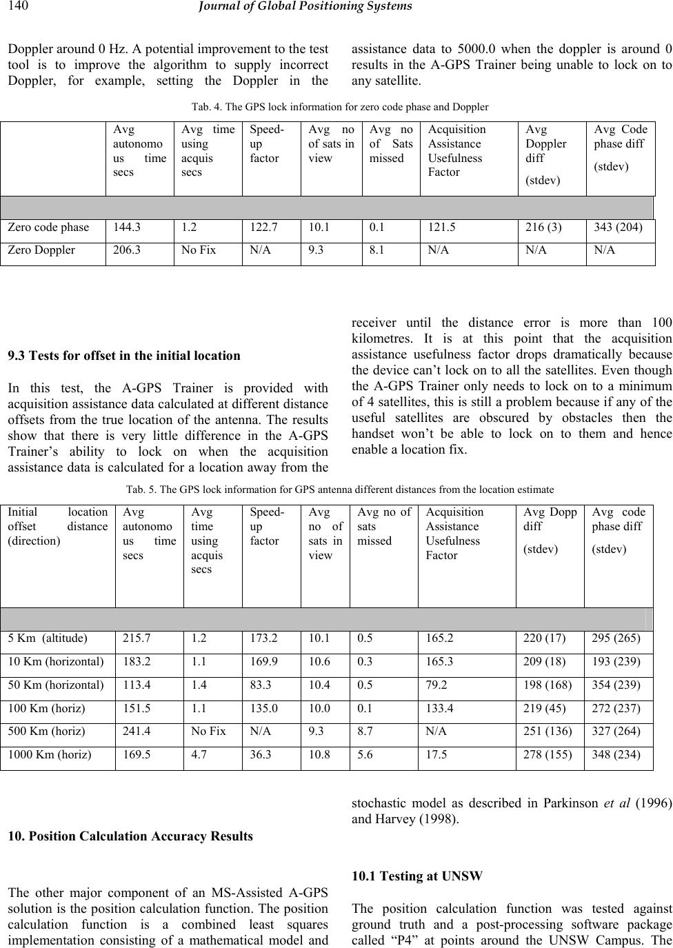 140 Journal of Global Positioning Systems Doppler around 0 Hz. A potential improvement to the test tool is to improve the algorithm to supply incorrect Doppler, for example, setting the Doppler in the assistance data to 5000.0 when the doppler is around 0 results in the A-GPS Trainer being unable to lock on to any satellite. Tab. 4. The GPS lock information for zero code phase and Doppler Avg autonomo us time secs Avg time using acquis secs Speed- up factor Avg no of sats in view Avg no of Sats missed Acquisition Assistance Usefulness Factor Avg Doppler diff (stdev) Avg Code phase diff (stdev) Zero code phase 144.3 1.2 122.7 10.1 0.1 121.5 216 (3) 343 (204) Zero Doppler 206.3 No Fix N/A 9.3 8.1 N/A N/A N/A 9.3 Tests for offset in the initial location In this test, the A-GPS Trainer is provided with acquisition assistance data calculated at different distance offsets from the true location of the antenna. The results show that there is very little difference in the A-GPS Trainer’s ability to lock on when the acquisition assistance data is calculated for a location away from the receiver until the distance error is more than 100 kilometres. It is at this point that the acquisition assistance usefulness factor drops dramatically because the device can’t lock on to all the satellites. Even though the A-GPS Trainer only needs to lock on to a minimum of 4 satellites, this is still a problem because if any of the useful satellites are obscured by obstacles then the handset won’t be able to lock on to them and hence enable a location fix. Tab. 5. The GPS lock information for GPS antenna different distances from the location estimate Initial location offset distance (direction) Avg autonomo us time secs Avg time using acquis secs Speed- up factor Avg no of sats in view Avg no of sats missed Acquisition Assistance Usefulness Factor Avg Dopp diff (stdev) Avg code phase diff (stdev) 5 Km (altitude) 215.7 1.2 173.2 10.1 0.5 165.2 220 (17) 295 (265) 10 Km (horizontal) 183.2 1.1 169.9 10.6 0.3 165.3 209 (18) 193 (239) 50 Km (horizontal) 113.4 1.4 83.3 10.4 0.5 79.2 198 (168) 354 (239) 100 Km (horiz) 151.5 1.1 135.0 10.0 0.1 133.4 219 (45) 272 (237) 500 Km (horiz) 241.4 No Fix N/A 9.3 8.7 N/A 251 (136) 327 (264) 1000 Km (horiz) 169.5 4.7 36.3 10.8 5.6 17.5 278 (155) 348 (234) 10. Position Calculation Accuracy Results The other major component of an MS-Assisted A-GPS solution is the position calculation function. The position calculation function is a combined least squares implementation consisting of a mathematical model and stochastic model as described in Parkinson et al (1996) and Harvey (1998). 10.1 Testing at UNSW The position calculation function was tested against ground truth and a post-processing software package called “P4” at points around the UNSW Campus. The 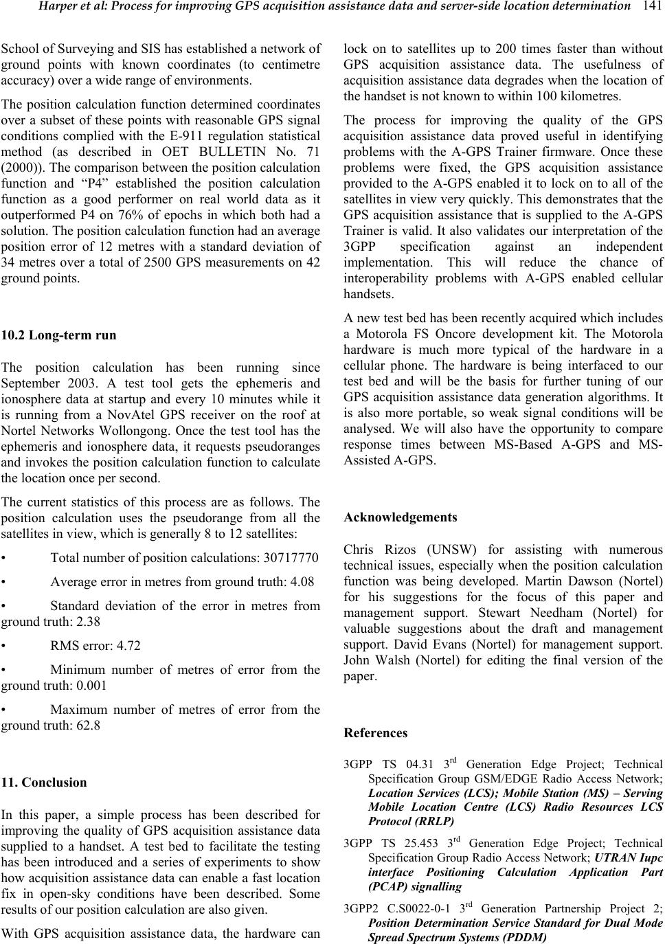 Harper et al: Process for improving GPS acquisition assistance data and server-side location determination 141 School of Surveying and SIS has established a network of ground points with known coordinates (to centimetre accuracy) over a wide range of environments. The position calculation function determined coordinates over a subset of these points with reasonable GPS signal conditions complied with the E-911 regulation statistical method (as described in OET BULLETIN No. 71 (2000)). The comparison between the position calculation function and “P4” established the position calculation function as a good performer on real world data as it outperformed P4 on 76% of epochs in which both had a solution. The position calculation function had an average position error of 12 metres with a standard deviation of 34 metres over a total of 2500 GPS measurements on 42 ground points. 10.2 Long-term run The position calculation has been running since September 2003. A test tool gets the ephemeris and ionosphere data at startup and every 10 minutes while it is running from a NovAtel GPS receiver on the roof at Nortel Networks Wollongong. Once the test tool has the ephemeris and ionosphere data, it requests pseudoranges and invokes the position calculation function to calculate the location once per second. The current statistics of this process are as follows. The position calculation uses the pseudorange from all the satellites in view, which is generally 8 to 12 satellites: • Total number of position calculations: 30717770 • Average error in metres from ground truth: 4.08 • Standard deviation of the error in metres from ground truth: 2.38 • RMS error: 4.72 • Minimum number of metres of error from the ground truth: 0.001 • Maximum number of metres of error from the ground truth: 62.8 11. Conclusion In this paper, a simple process has been described for improving the quality of GPS acquisition assistance data supplied to a handset. A test bed to facilitate the testing has been introduced and a series of experiments to show how acquisition assistance data can enable a fast location fix in open-sky conditions have been described. Some results of our position calculation are also given. With GPS acquisition assistance data, the hardware can lock on to satellites up to 200 times faster than without GPS acquisition assistance data. The usefulness of acquisition assistance data degrades when the location of the handset is not known to within 100 kilometres. The process for improving the quality of the GPS acquisition assistance data proved useful in identifying problems with the A-GPS Trainer firmware. Once these problems were fixed, the GPS acquisition assistance provided to the A-GPS enabled it to lock on to all of the satellites in view very quickly. This demonstrates that the GPS acquisition assistance that is supplied to the A-GPS Trainer is valid. It also validates our interpretation of the 3GPP specification against an independent implementation. This will reduce the chance of interoperability problems with A-GPS enabled cellular handsets. A new test bed has been recently acquired which includes a Motorola FS Oncore development kit. The Motorola hardware is much more typical of the hardware in a cellular phone. The hardware is being interfaced to our test bed and will be the basis for further tuning of our GPS acquisition assistance data generation algorithms. It is also more portable, so weak signal conditions will be analysed. We will also have the opportunity to compare response times between MS-Based A-GPS and MS- Assisted A-GPS. Acknowledgements Chris Rizos (UNSW) for assisting with numerous technical issues, especially when the position calculation function was being developed. Martin Dawson (Nortel) for his suggestions for the focus of this paper and management support. Stewart Needham (Nortel) for valuable suggestions about the draft and management support. David Evans (Nortel) for management support. John Walsh (Nortel) for editing the final version of the paper. References 3GPP TS 04.31 3rd Generation Edge Project; Technical Specification Group GSM/EDGE Radio Access Network; Location Services (LCS); Mobile Station (MS) – Serving Mobile Location Centre (LCS) Radio Resources LCS Protocol (RRLP) 3GPP TS 25.453 3rd Generation Edge Project; Technical Specification Group Radio Access Network; UTRAN Iupc interface Positioning Calculation Application Part (PCAP) signalling 3GPP2 C.S0022-0-1 3rd Generation Partnership Project 2; Position Determination Service Standard for Dual Mode Spread Spectrum Systems (PDDM)  142 Journal of Global Positioning Systems Djuknic G, Richton R (2001), Geolocation and Assisted GPS, IEEE Comminications, February 2001 Harvey BR (1998), Practical Least Squares for Statistics and Surveyors, The University of New South Wales School of Geomatic Engineering Monograph 13 Heinrich G, Eissfeller B, Pany T, Weigel R, Ehm H, Schmid A , Neubauer A , Rohmer G , Ávila-Rodríguez J, HIGAPS A Highly Integrated Galileo/GPS Chipset for Consumer Applications, GPS World September 2001 Syrjarinne J, Possibiliies for GPS Time Recovery with GSM Network Assistance, ION GPS 2000, 19-22 September 2000, Salt Lake City, UT Parkinson and Spilker, Eds., Axelrand and Enge, Assoc. Eds (1996) Global Positioning System: Theory and Applications Volume I,American Institute of Aeronautics and Astronautics van Diggelen F and Abraham C (2001) Indoor GPS Technology, CTIA Wireless-Agenda, Dallas, May 2001 Zhao Y (2002), Standardization of Mobile Phone Positioning for 3G Systems, IEEE Communications Magazine, July 2002 |