Paper Menu >>
Journal Menu >>
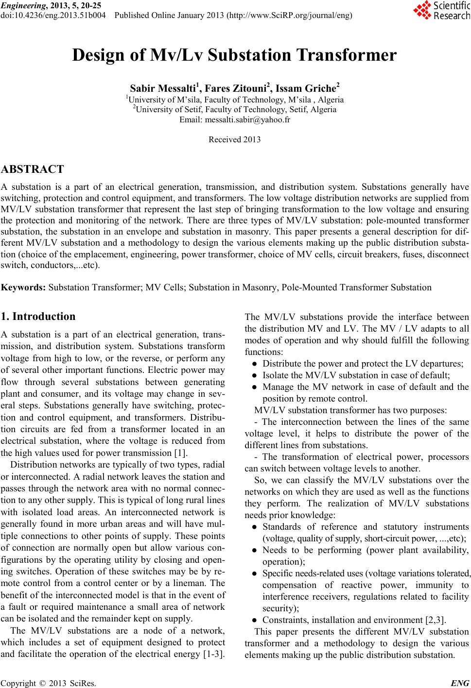 Engineering, 2013, 5, 20-25 doi:10.4236/eng.2013.51b004 Published Online January 2013 (http://www.SciRP.org/journal/eng) Copyright © 2013 SciRes. ENG Design of Mv/Lv Substation Transformer Sabir Messal ti1, Fares Z itou ni2, Issam Griche2 1University of M’sila, Faculty of Technology, M’sila , Algeria 2Universi ty of Setif, F aculty of Technology, Setif, Algeria Email: messalti.sabir@yahoo.fr Received 2013 ABSTRACT A substation is a part of an electrical generation, transmission, and distribution system. Substations generally have switching, pr otec tion and co ntro l eq uipment, and transformers. T he lo w voltage distr ibutio n net works are s upp lied fro m MV/LV substation transformer that represent the last step of bringing transformation to the low voltage and ensuring the protection and monitoring of the network. There are three types of MV/LV substation: pole-mounted transformer substation, the substation in an envelope and substation in masonry. This paper presents a general description for dif- ferent MV/LV substation and a methodology to design the various elements making up the public distribution substa- tion (choice of the emplacement, engineering, power transformer, choice of MV cells, circuit breakers, fuses, disconnect switch, conductors,...etc). Keywords: Substa tion Transformer; MV Cells ; Substation in Masonr y, Pole-Mounted Transformer Substation 1. Introduction A substation is a part of an electrical generation, trans- mission, and distribution system. Substations transform voltage from high to low, or the reverse, or perform any of several other important functions. Electric power may flow through several substations between generating plant and consumer, and its voltage may change in sev- eral steps. Substations generally have switching, protec- tion and control equipment, and transformers. Distribu- tion circuits are fed from a transformer located in an electrical substation, where the voltage is reduced from the high values used for po we r transmi s sion [1]. Distribution networ ks are typically of two types, radial or interconnected. A radial network leaves the station and passes through the network ar ea with no nor mal connec- tion to any other supply. This is typical of l ong rural lines with isolated load areas. An interconnected network is generally found in more urban areas and will have mul- tiple connections to other points of supply. These points of connection are normally open but allow various con- figurations by the operating utility by closing and open- ing switches. Operation of these switches may be by re- mote control from a control center or by a lineman. The benefit of the interconnected model is that in the event of a fault or required maintenance a small area of network can be isolated and the remainder kept on supply. The MV/LV substations are a node of a network, which includes a set of equipment designed to protect and facilitate the operation of the electrical energy [1-3]. The MV/LV substations provide the interface between the distribution MV and LV. The MV / LV adapts to all modes of operation and why should fulfill the following functions: ● Distribute the power and protect the LV departures; ● Isolate the MV/LV substation in case of default; ● Manage the MV network in case of default and the position by remote control. MV/LV substation transformer has two purposes: - The interconnection between the lines of the same voltage level, it helps to distribute the power of the different lines from substations. - The transformation of electrical power, processors can switch be tween voltage levels to anot her. So, we can classify the MV/LV substations over the networks on which they are used as well as the functions they perform. The realization of MV/LV substations needs prior knowledge: ● Standards of reference and statutory instruments (voltage, quality of supply, short-circuit power, ...,etc); ● Needs to be performing (power plant availability, operation); ● Specific needs-related uses (vo lta ge variations tolera te d, compensation of reactive power, immunity to interference receivers, regulations related to facility security); ● Constraints, installation and environment [2,3]. This paper presents the different MV/LV substation transformer and a methodology to design the various elements making up the publi c distr ibution substat ion. 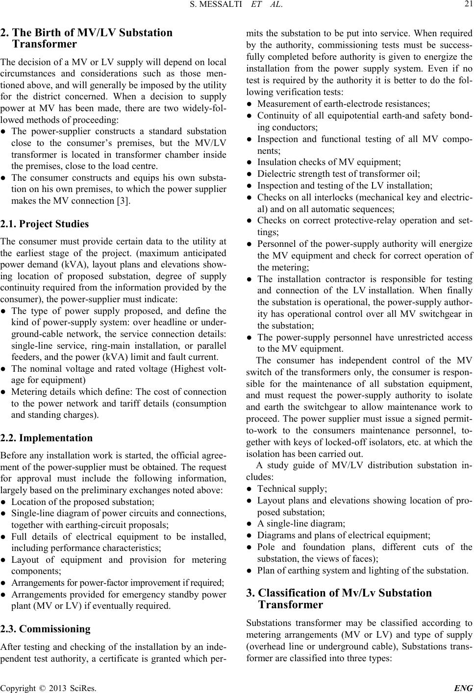 S. MESSALTI ET AL. Copyright © 2013 SciRes. ENG 21 2. The Birth of MV/LV Substation Transformer The decision of a MV or LV supply will depend on local circumstances and considerations such as those men- tioned above, and will generally be imposed by the utility for the district concerned. When a decision to supply power at MV has been made, there are two widely-fol- lowed methods of proceeding: ● The power-supplier constructs a standard substation close to the consumer’s premises, but the MV/LV transformer is located in transformer chamber inside the premises, close to the load centre. ● The consumer constructs and equips his own substa- tion on his own pre mises, to which the power supplie r makes the MV connection [3]. 2.1. Project Studies The consumer must provide certain data to the utility at the earliest stage of the project. (maximum anticipated power demand (kVA), layout plans and elevations show- ing location of proposed substation, degree of supply continuity required from the information provided by the consumer), the power-supplier must indic a te : ● The type of power supply proposed, and define the kind o f power-supply syste m: over headline or under- ground-cable network, the service connection details: single-line service, ring-main installation, or parallel feed ers, and the power (kVA) l imit and fault cur rent. ● The nominal voltage and rated voltage (Highest volt- age fo r eq uipment) ● Metering details which define: The cost of connection to the power network and tariff details (consumption and st anding charges). 2.2. Implementation Before any installation work is started, the official agree- ment of the po wer -supplier must be obtained. The request for approval must include the following information, largely based on the preliminary exchanges noted above: ● Location of the proposed substation; ● Single-line diagram of power circuits and connections, together with ear thing-circuit propo sals; ● Full details of electrical equipment to be installed, including performance characteristics; ● Layout of equipment and provision for metering components; ● Arr angements for power-fa ctor im provem ent if required; ● Arrangements provided for emergency standby power plant (MV or LV) if eventually required. 2.3. Commissioning After testing and checking of the installation by an inde- pendent test authority, a certificate is granted which per- mits the substation to be put into service. When required by the authority, commissioning tests must be success- fully completed before authority is given to energize the installation from the power supply system. Even if no test is required by the authority it is better to do the fol- lowing veri fication tests: ● Measurement of earth-electro de resistances; ● Continuity of all equipotential earth-and safety bond- ing conductors; ● Inspection and functional testing of all MV compo- nents; ● Insulation checks of MV equipment; ● Dielectric strength test o f transformer oil; ● Inspection a nd te sting of the L V installation; ● Chec ks on al l inter loc ks (mec hanic al ke y and e lectr ic- al) and on all auto matic sequences; ● Checks on correct protective-relay operation and set- tings; ● Personnel of the power-supply authority will energize the MV equipment and check for correct operation of the metering; ● The installation contractor is responsible for testing and connection of the LV installation. When finally the substatio n is oper ational, the po wer-sup pl y aut hor- ity has operational control over all MV switchgear in the substation; ● The power-supply personnel have unrestricted access to the MV equipment. The consumer has independent control of the MV switch of the transformers only, the consumer is respon- sible for the maintenance of all substation equipment, and must request the power-supply authority to isolate and earth the switchgear to allow maintenance work to proceed. The power supplier must issue a signed permit- to-work to the consumers maintenance personnel, to- gether with ke ys of lo cked -off isolators, e tc. at which the isolation has been carried out. A study guide of MV/LV distribution substation in- cludes: ● Te chnica l supply; ● Layout plans and elevations showing location of pro- posed substation; ● A single-li ne diagram; ● Diagrams and plans of electrical equipment; ● Pole and foundation plans, different cuts of the substation, the views of faces); ● Pla n of earthing system and li ghting of the substatio n. 3. Classification of Mv/Lv Substation Transformer Substations transformer may be classified according to metering arrangements (MV or LV) and type of supply (overhead line or underground cable), Substations trans- former are classified into three type s: 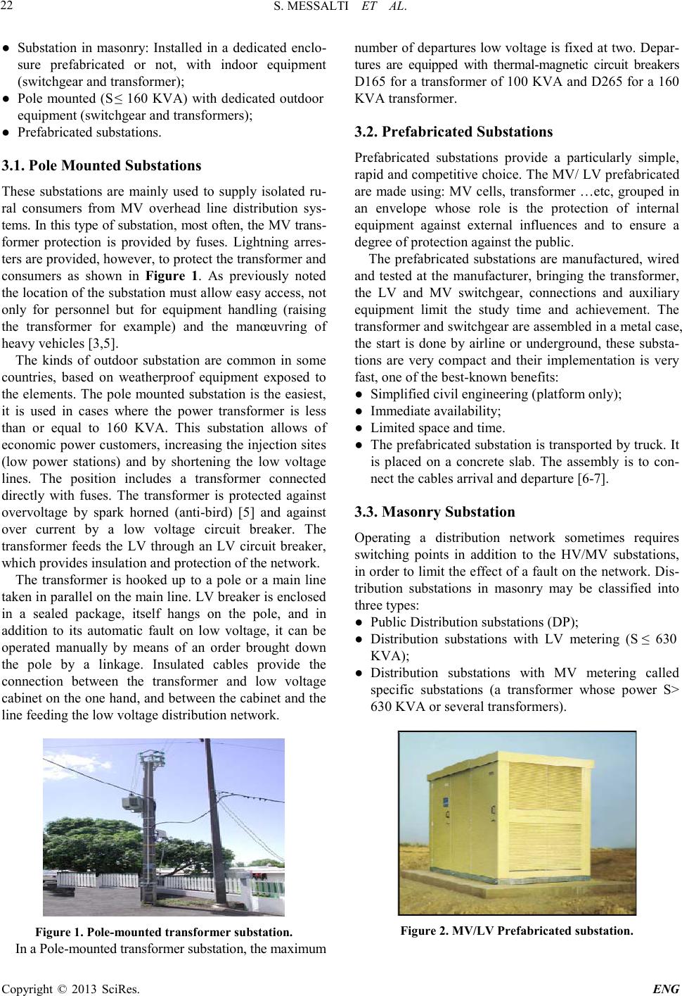 S. MESSALTI ET AL. Copyright © 2013 SciRes. ENG 22 ● Substation in masonry: Installed in a dedicated enclo- sure prefabricated or not, with indoor equipment (switchgear and transformer); ● Pole mounted ( S ≤ 160 KVA) with dedicated outdoor equipment (switchgear a nd tr a nsformers); ● Prefabricated substations. 3.1. Pole Mounted Substations These substations are mainly used to supply isolated ru- ral consumers from MV overhead line distribution sys- tems . In thi s type o f substa tion, most oft en, the MV tra ns- former protection is provided by fuses. Lightning arres- ters are provided, however, to protect the transformer and consumers as shown in Figure 1. As previously noted the locatio n of the s ubstation must allo w easy acce ss, not only for personnel but for equipment handling (raising the transformer for example) and the manœuvring of heav y vehicles [3,5 ]. The kinds of outdoor substation are common in some countries, based on weatherproof equipment exposed to the elements. The pole mounted substation is the easiest, it is used in cases where the power transformer is less than or equal to 160 KVA. This substation allows of economic power customers, increasing the injection sites (low power stations) and by shortening the low voltage lines. The position includes a transformer connected directly with fuses. The transformer is protected against overvoltage by spark horned (anti-bird) [5] and against over current by a low voltage circuit breaker. The transformer feeds the LV through an LV circuit breaker, which provides insulation and protection of the network. The transformer is hooked up to a pole or a main line taken in parallel on the main line. LV breaker is enclosed in a sealed package, itself hangs on the pole, and in addition to its automatic fault on low voltage, it can be operated manually by means of an order brought down the pole by a linkage. Insulated cables provide the connection between the transformer and low voltage cab inet o n the o ne ha nd, and be twee n the cab ine t a nd t he line feeding the low voltage distribution network. Figure 1 . Pole-mounted transformer substation. In a Pole-mounted transformer substation, the maximum number of departures low voltage is fixed at two. Depar- tures are equipped with thermal-magnetic circuit breakers D165 for a transformer of 100 KVA and D265 for a 160 KVA transf ormer. 3.2. Prefabricated Substations Prefabricated substations provide a particularly simple, rapid and competitive choice. The MV/ LV prefabricated are made using: MV cells, transformer …etc, grouped in an envelope whose role is the protection of internal equipment against external influences and to ensure a degree of protection against the p ublic. The prefabricated substations are manufactured, wired and tested at the manufacturer, bringing the transformer, the LV and MV switchgear, connections and auxiliary equipment limit the study time and achievement. The transformer and switchgear are assembled in a metal case, the start is done by airline or underground, these substa- tions are very compact and their implementation is very fast, one of the best-known b e nefits: ● Simplified ci vil engineering (platform only); ● Immediate availability; ● Limited space and time. ● The prefabricated substation is transported by truck. It is placed on a concrete slab. The assembly is to con- nect the cables arrival and departure [6-7]. 3.3. Masonry Substation Operating a distribution network sometimes requires switching points in addition to the HV/MV substations, in order to limit the effect of a fault on the net work. Dis- tribution substations in masonry may be classified into three types: ● Public Distrib ution substations (DP); ● Distribution substations with LV metering (S ≤ 630 KVA) ; ● Distribution substations with MV metering called specific substations (a transformer whose power S> 630 KVA or several transformers). Figure 2 . MV/LV Prefabricated s ub s t ation. 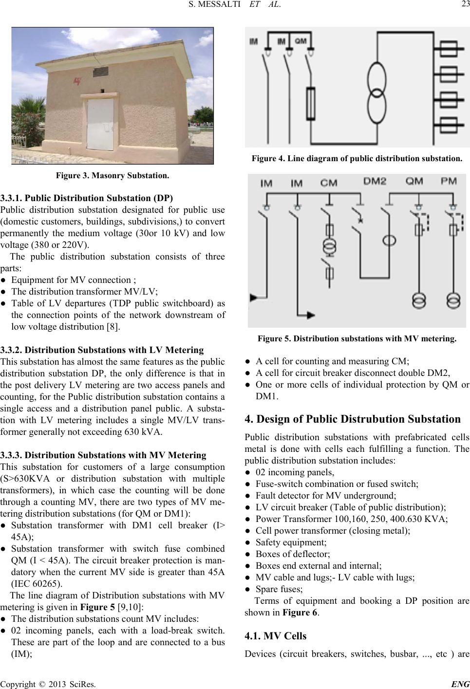 S. MESSALTI ET AL. Copyright © 2013 SciRes. ENG 23 Figure 3 . Masonry Substation. 3.3.1. Public Distribution Substation (DP) Public distribution substation designated for public use (domestic customers, buildings, subdivisions,) to convert permanently the medium voltage (30or 10 kV) and low voltage (380 or 220V). The public distribution substation consists of three part s : ● Equipment for MV c onnection ; ● The distrib utio n tra nsformer M V /L V ; ● Table of LV departures (TDP public switchboard) as the connection points of the network downstream of low voltage distribution [8]. 3.3.2. Distribution Subst ations with LV Metering This substatio n has almost the same features as the public distribution substation DP, the only difference is that in the post delivery LV metering are two access panels and counti n g, fo r the Pub lic distribution sub station contai ns a single access and a distribution panel public. A substa- tion with LV metering includes a single MV/LV trans- former generally not exceeding 630 kVA. 3.3.3. Distribution Subst ations with MV Metering This substation for customers of a large consumption (S>630KVA or distribution substation with multiple transformers), in which case the counting will be done through a counting MV, there are two types of MV me- tering distrib ution substatio ns (for QM or DM1) : ● Substation transformer with DM1 cell breaker (I> 45A); ● Substation transformer with switch fuse combined QM (I < 45A). The circuit breaker protection is man- datory when the current MV side is greater than 45A (IEC 60265). The line diagram of Distribution substations with MV metering is give n in Figure 5 [9,10]: ● The distribution sub stations count MV includ es: ● 02 incoming panels, each with a load-break switch. These are part of the loop and are connected to a bus (IM); Figure 4 . Line diagram of public distribution su bstation. Figure 5 . Distribut ion sub stations with MV metering. ● A cell for counting and measuring CM; ● A cell for circuit breaker disconnect double DM2, ● One or more cells of individual protection by QM or DM1. 4. Design of Public Distrubution Substation Public distribution substations with prefabricated cells metal is done with cells each fulfilling a function. The public distrib ution substatio n includes: ● 02 incoming panels, ● Fuse-s witc h combination or fused switch; ● Fault detector for MV underground; ● LV circuit brea ker (Table of public distrib ution); ● Power Trans f orme r 100,160, 250, 400.630 KVA ; ● Cell power transfor mer (closing metal); ● Safety equipment; ● Boxes of deflector; ● Boxes end external and internal; ● MV cable and lugs;- LV cable with lugs; ● Spare fuses; Terms of equipment and booking a DP position are shown in Figure 6. 4.1. MV Cells Devices (circuit breakers, switches, busbar, ..., etc ) are  S. MESSALTI ET AL. Copyright © 2013 SciRes. ENG 24 integrated in metal casings that facilitate the installation and operation, safe people, these envelopes are called cells, they can achieve MV part transformer stations. The different cells Schneider Electric 36 or 24 KV in the composition of MV / LV sub station trans former are: ● IM, IMC, IMB switch; ● PM fused switch; ● QM fuse-s witch combination; ● DM1-A, DM1-D, single-isolation SF6 type circuit breaker; ● DM2 double-isolation SF6 type circuit br e a ker ; ● CM, CM2 voltage transfor mers; ● SM disconnector; ● GBC-A, GBC-B current and/or voltage measurement s ; ● GIM intermediate bus unit; ● GBM connection unit,…[10 ]. 4.2. Fault Current Indicator The fault current detector is designed for the detection of permanent fault s on MV u nderground networ ks , covering all types of MV systems [10]. 4.3. Choice of MV/LV Transformer The MV/LV power transformers are usually step-down, they used to supply low voltage from a medium voltage network. They are characterized by the rated power Pn ( 50, 100, 160, 250, 400, 630, 800, 1000, 1250 1600KVA,..) and rated primary and secondary voltages (30/0.4 KV for overhead networks and 10/0.4 KV for under ground M V ne t works) . I n order to select an optimal power (kVA) rating for a transformer, the following fac- tors must be taken into account list the po wer of installed power-consuming equipment Pi, the power factor, the utilization factor (ku) ,the simultaneity factor (ks), the rated power Sn transformer is give n by: 1cos ii n iu s ni ii PK K S ηϕ = ⋅⋅ =⋅ ∑ (1) 4.4. Choice of LV Circuit Breaker The main role of a circuit breaker is to protect the electrical s ystem during fault s, overlo ad and short cir cuit; it is designed to open a circuit automatically when the current flowing through it exceeds a pred etermined value. To effectively function, the trigger circuit breaker must take into account the evolution of the receptors [11]. The LV circuit breaker can be fixed, removable, CLPG (general protection cell), removable LV circuit breaker, or TDP (Public Distribution Table). The choice of the LV circuit breaker will be from the secondary rated current. 4.5. Public Distribution Table The table for public distribution (TDP) is the lower voltage distrib ution station public ; it is used at the top of LV circuit to p r ovide the following main functions: ● Power supplied of LV consumer; ● The distribution by multiplying the number of departures (4 or 8 departures). ● Opening, isolation of each departure. The table for public distribution includes a switching device which can be a general switch or a circuit breaker [12] 4.6. Choice of Cables and Connections The connection between the MV cells and transformer (MV side) will be through a MV cable, able to pass the input current of the network, the connection of the transformer (LV terminals) with LV circuit breaker will be through a LV cable. LV cable length is calculated by measuring the distance between the transformer and LV circuit breaker. The number of cables per phase is determined from the current supplied by the transformer and cable characteristics. The optimal choice of the cable must meet several criteria (rated current, operating temperature, fashion poses, voltage drop, and short circuit. 4.7. Choice of Fuses Fuses are a very widely used means of protecting distri- bution transformers, mainly due to their simplicity and the correspondingly reduced cost of the equipment. The rules regarding the selection of fuses, given by the man- ufacturers and dependent upon the characteristics of each fuse type, cover the following criteria: the transfor- mer’s operating voltage, the switching currents, and technology of fuses [10]. 4.8. Materials for Operation and Safety Safety equipment for a MV/LV substation transfor mer consists essentially of: ● Insul at i ng sto o l. ● Insul at i ng mat. ● Insul at i ng glo ve s. ● Voltage detector. ● Earthing attac hments; ● Safety alarms and plaque and fire-extinguishing [3,8]. 5. Conclusion In this paper, we presented a synthesis of the various MV/ LV substation transformer, we have explained below the various documents constituting technical stud y, a detailed study of the public distribution substations (line diagram, the plan equipment, the choice of MV  S. MESSALTI ET AL. Copyright © 2013 SciRes. ENG 25 cells and MV / LV transformer, choosing the LV circuit breaker, the cables and the necessar y safety equipment). Operating a distribution network requires switching points in addition to the MV/LV substations, in order to limit the effect of a fault on the network. To build a MV/LV substation transformer, it is necessary to size a number of parameters to achieve the appropriate wiring diagram. The development of these components must meet certain conditions dictated by the dual concern for the safety of operation and lower operating costs. These construction conditions can be classified into conditions related to tension, conditions relating to the thermal effects of the current, and conditions relating to the safety of operating personnel. REFERENCES [1] B. Joyeux Bouillon, J.C Turpain, G. Valentin - R. Fondeur Postes à moyenne tension ”Techniques de l’Ingénieur, D4600, 1996. [2] A. Croguennoc , Protection des réseaux à moyenne tension de distribution publique, ”Techniques de l’Ingénieur, D 4 810,1991 [3] Connection to the MV public distribution network, Schneider Electric - Electrical installation guide (2010). [4] Didier Fulchiron (2005), Protection des transformateurs de postes MT/BT, n° 192, Schneider Electric. [5] Christian Gazzola Ferraz,Bernard, Vuillet Ferraz (1998), Protecti o avale et co upure po ur les postes MT/BT sur poteau, Systèmes d’énergie électrique. Guide de référence, Les po s te MT/BT. [6] Poste préfabriqué MT/BT d’extérieur à votre service, Notice d’utilisation LR 71-A1.LR 71-B1, Schneider Electric. Edition (2000). [7] Postes d’extérieur MT/BT préfabriqués à couloir de manoeuvre 1 à 24 kV Gamme LR71, Schneider Electric,edition (2002). [8] Guide technique de la moyenne tension (1984) SONELGAZ. [9] Guide de la distribution moyenne tension (2002, Schneider Electric. [10] Catalogue Cellules modulaires, SM6 Merlin Gerin 36 KV, 2003. [11] Alain Croguennoc, Protection des réseaux à b asse tensio n de distribution publique, Techniques de l'ingénieur D 4815, 19 91 . [12] Catalogue KAHRAKIB, Tableau de distribution publique, 2005. |