Paper Menu >>
Journal Menu >>
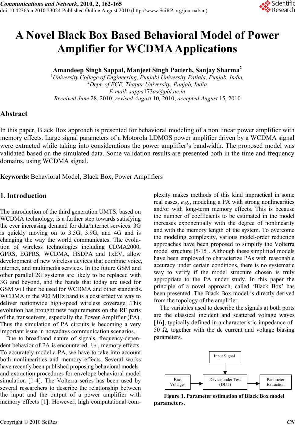 Communications and Network, 2010, 2, 162-165 doi:10.4236/cn.2010.23024 Published Online August 2010 (http://www.SciRP.org/journal/cn) Copyright © 2010 SciRes. CN A Novel Black Box Based Behavioral Model of Power Amplifier for WCDMA Applications Amandeep Singh Sappal, Manjeet Singh Patterh, Sanjay Sharma2 1University College of Engineering, Punjabi University Patiala, Punjab, India, 2Dept. of ECE, Thapar University, Punjab, India E-mail: sappa173as@pbi.ac.in Received June 28, 2010; revised August 10, 2010; accepted August 15, 2010 Abstract In this paper, Black Box approach is presented for behavioral modeling of a non linear power amplifier with memory effects. Large signal parameters of a Motorola LDMOS power amplifier driven by a WCDMA signal were extracted while taking into considerations the power amplifier’s bandwidth. The proposed model was validated based on the simulated data. Some validation results are presented both in the time and frequency domains, using WCDMA signal. Keywords: Behavioral Model, Black Box, Power Amplifiers 1. Introduction The introduction of the third generation UMTS, based on WCDMA technology, is a further step towards satisfying the ever increasing demand for data/internet services. 3G is quickly moving on to 3.5G, 3.9G, and 4G and is changing the way the world communicates. The evolu- tion of wireless technologies including CDMA2000, GPRS, EGPRS, WCDMA, HSDPA and 1xEV, allow development of new wireless devices that combine voice, internet, and multimedia services. In the future GSM and other parallel 2G systems are likely to be replaced with 3G and beyond, and the bands that today are used for GSM will then be used for WCDMA and other standards. WCDMA in the 900 MHz band is a cost effective way to deliver nationwide high-speed wireless coverage .This evolution has brought new requirements on the RF parts of the transceivers, especially the Power Amplifier (PA). Thus the simulation of PA circuits is becoming a very important issue in nowadays communication scenarios. Due to broadband nature of signals, frequency-depen- dent behavior of PA is encountered, i.e ., memory effects. To accurately model a PA, we have to take into account both nonlinearities and memory effects. Several works have recently been published proposing behavioral models and extraction procedures for envelope behavioral model simulation [1-4]. The Volterra series has been used by several researchers to describe the relationship between the input and the output of a power amplifier with memory effects [1]. However, high computational com- plexity makes methods of this kind impractical in some real cases, e.g., modeling a PA with strong nonlinearities and/or with long-term memory effects. This is because the number of coefficients to be estimated in the model increases exponentially with the degree of nonlinearity and with the memory length of the system. To overcome the modeling complexity, various model-order reduction approaches have been proposed to simplify the Volterra model structure [5-15]. Although these simplified models have been employed to characterize PAs with reasonable accuracy under certain conditions, there is no systematic way to verify if the model structure chosen is truly appropriate to the PA under study. In this paper the principle of a novel approach, called ‘Black Box’ has been presented. The Black Box model is directly derived from the topology of the amplifier. The variables used to describe the signals at both ports are the classical incident and scattered voltage waves [16], typically defined in a characteristic impedance of 50 Ω, together with the dc current and voltage biasing parameters. Input Signal Figure 1. Parameter estimation of Black Box model parameters. Device under Test (DUT) Bias Voltages Parameter Extraction 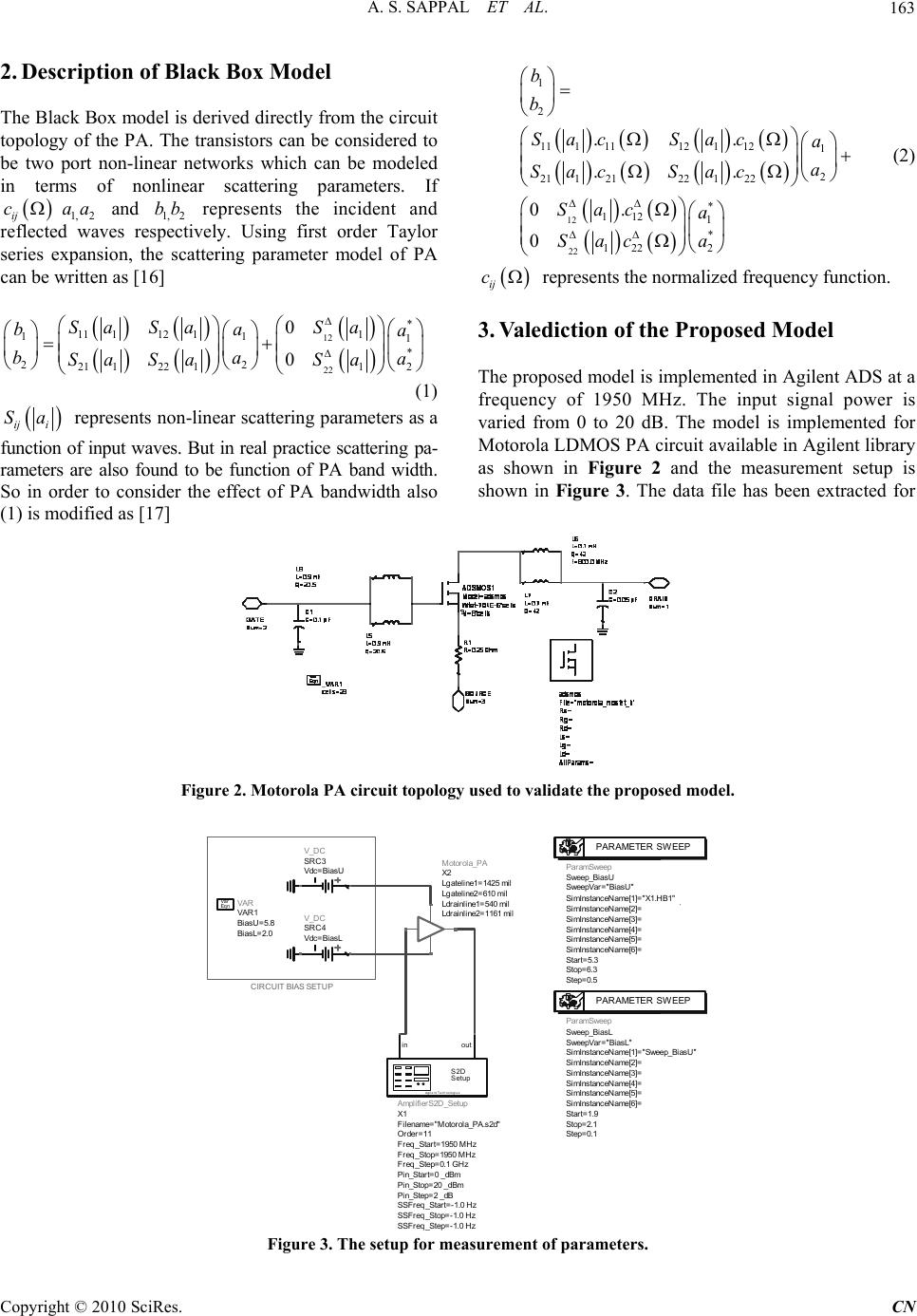 A. S. SAPPAL ET AL.163 2. Description of Black Box Model The Black Box model is derived directly from the circuit topology of the PA. The transistors can be considered to be two port non-linear networks which can be modeled in terms of nonlinear scattering parameters. If 1,2 and 1,2 represents the incident and reflected waves respectively. Using first order Taylor series expansion, the scattering parameter model of PA can be written as [16] ij caa bb 12 22 * 11 11211 11 1 * 22 2 21 12211 0 0 Sa SaSa ba a ba a Sa SaSa (1) ij i Sa 12 22 1 2 1111112 1 121 2 21121221 22 * 112 1 * 2 122 .. .. 0. 0 b b Sac Saca a SacSac Sac a a Sac (2) ij c represents the normalized frequency function. 3. Valediction of the Proposed Model The proposed model is implemented in Agilent ADS at a frequency of 1950 MHz. The input signal power is varied from 0 to 20 dB. The model is implemented for Motorola LDMOS PA circuit available in Agilent library as shown in Figure 2 and the measurement setup is shown in Figure 3. The data file has been extracted for represents non-linear scattering parameters as a function of input waves. But in real practice scattering pa- rameters are also found to be function of PA band width. So in order to consider the effect of PA bandwidth also (1) is modified as [17] Figure 2. Motorola PA circuit topology used to validate the proposed model. CIRCUIT BIAS SETUP Motorola_PA X2 Ldrainline2=1161 mil Ldrainline1=540 mil Lgateline2=610 mil Lgateline1=1425 mil AmplifierS2D_Setup X1 SSFreq_Step=-1.0 Hz SSFreq_Stop=-1.0 Hz SSFreq_Start=-1.0 Hz Pin_Step=2 _dB Pin_Stop=20 _dBm Pin_Start=0 _dBm Freq_Step=0.1 GHz Freq_Stop=1950 MHz Freq_Start=1950 MHz Order=11 Filename="Motorola_PA.s2d" S2D Setup Agilent Technologies outin ParamSweep Sweep_BiasL Step=0.1 Stop=2.1 Start=1.9 SimInstanceName[6]= SimInstanceName[5]= SimInstanceName[4]= SimInstanceName[3]= SimInstanceName[2]= SimInstanceName[1]="Sweep_BiasU" SweepVar="BiasL" PARAMETER SWEEP ParamSweep Sweep_BiasU Step=0.5 Stop=6.3 Start=5.3 SimInstanceName[6]= SimInstanceName[5]= SimInstanceName[4]= SimInstanceName[3]= SimInstanceName[2]= SimInstanceName[1]="X1.HB1" SweepVar="BiasU" PARAMETER SWEEP V_DC SRC4 Vdc=Bias L V_DC SRC3 Vdc=Bias U VAR VAR1 Bi asL=2.0 Bi asU=5.8 Eqn Var Figure 3. The setup for measurement of parameters. Copyright © 2010 SciRes. CN 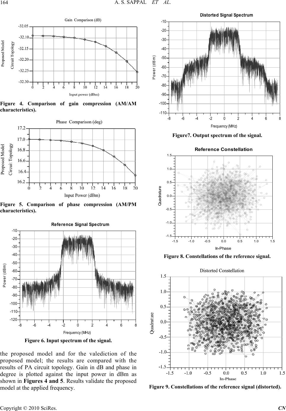 A. S. SAPPAL ET AL. 164 Figure 4. Comparison of gain compression (AM/AM characteristics). Figure 5. Comparison of phase compression (AM/PM characteristics). -6-4-20 2 4 6-88 -110 -100 -90 -80 -70 -60 -50 -40 -30 -20 -120 -10 Frequency (MHz) P ower (dB m ) R e f erence Si gna l S pectrum Figure 6. Input spectrum of the signal. the proposed model and for the valediction of the proposed model; the results are compared with the results of PA circuit topology. Gain in dB and phase in degree is plotted against the input power in dBm as shown in Figures 4 and 5. Results validate the proposed model at the applied frequency. -6-4-20246-8 8 -100 -90 -80 -70 -60 -50 -40 -30 -20 -110 -10 Frequency (MHz) P ower (dB m ) Di storte d Si gna l S pectrum Figure7. Output spectrum of the signal. -1.0-0.50.0 0.5 1.0-1.5 1.5 -1. 0 -0. 5 0.0 0.5 1.0 -1. 5 1.5 In-Phas e Quadrature Reference Constellation Figure 8. Constellations of the reference signal. Figure 9. Constellations of the reference signal (distorted). C opyright © 2010 SciRes. CN 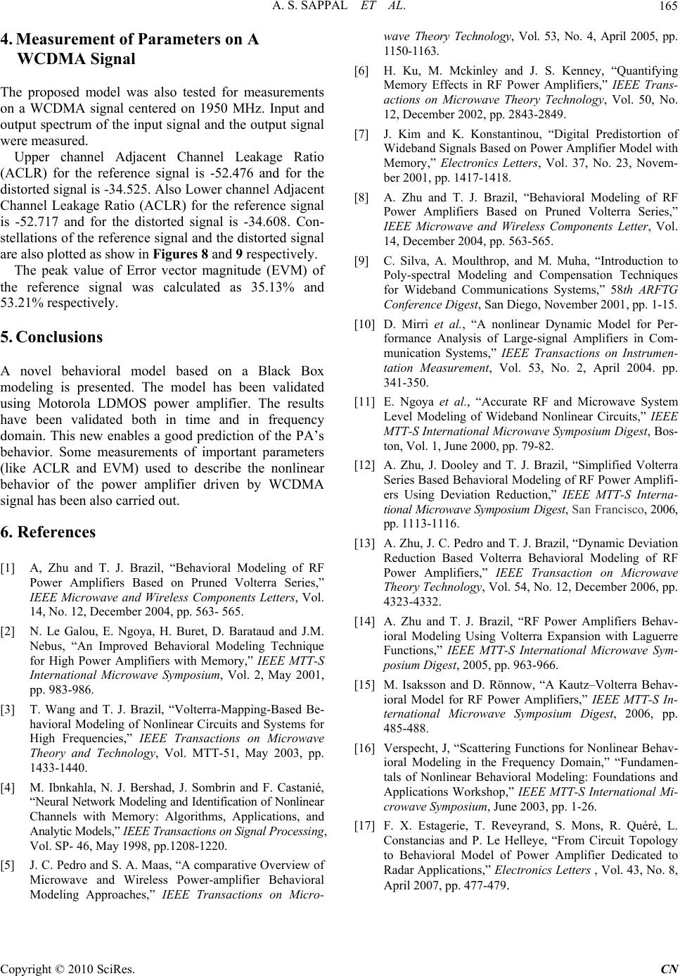 A. S. SAPPAL ET AL. Copyright © 2010 SciRes. CN 165 4. Measurement of Parameters on A WCDMA Signal The proposed model was also tested for measurements on a WCDMA signal centered on 1950 MHz. Input and output spectrum of the input signal and the output signal were measured. Upper channel Adjacent Channel Leakage Ratio (ACLR) for the reference signal is -52.476 and for the distorted signal is -34.525. Also Lower channel Adjacent Channel Leakage Ratio (ACLR) for the reference signal is -52.717 and for the distorted signal is -34.608. Con- stellations of the reference signal and the distorted signal are also plotted as show in Figures 8 an d 9 respectively. The peak value of Error vector magnitude (EVM) of the reference signal was calculated as 35.13% and 53.21% respectively. 5. Conclusions A novel behavioral model based on a Black Box modeling is presented. The model has been validated using Motorola LDMOS power amplifier. The results have been validated both in time and in frequency domain. This new enables a good prediction of the PA’s behavior. Some measurements of important parameters (like ACLR and EVM) used to describe the nonlinear behavior of the power amplifier driven by WCDMA signal has been also carried out. 6. References [1] A, Zhu and T. J. Brazil, “Behavioral Modeling of RF Power Amplifiers Based on Pruned Volterra Series,” IEEE Microwave and Wireless Components Letters, Vol. 14, No. 12, December 2004, pp. 563- 565. [2] N. Le Galou, E. Ngoya, H. Buret, D. Barataud and J.M. Nebus, “An Improved Behavioral Modeling Technique for High Power Amplifiers with Memory,” IEEE MTT-S International Microwave Symposium, Vol. 2, May 2001, pp. 983-986. [3] T. Wang and T. J. Brazil, “Volterra-Mapping-Based Be- havioral Modeling of Nonlinear Circuits and Systems for High Frequencies,” IEEE Transactions on Microwave Theory and Technology, Vol. MTT-51, May 2003, pp. 1433-1440. [4] M. Ibnkahla, N. J. Bershad, J. Sombrin and F. Castanié, “Neural Network Modeling and Identification of Nonlinear Channels with Memory: Algorithms, Applications, and Analytic Models,” IEEE Transactions on Signal Processing, Vol. SP- 46, May 1998, pp.1208-1220. [5] J. C. Pedro and S. A. Maas, “A comparative Overview of Microwave and Wireless Power-amplifier Behavioral Modeling Approaches,” IEEE Transactions on Micro- wave Theory Technology, Vol. 53, No. 4, April 2005, pp. 1150-1163. [6] H. Ku, M. Mckinley and J. S. Kenney, “Quantifying Memory Effects in RF Power Amplifiers,” IEEE Trans- actions on Microwave Theory Technology, Vol. 50, No. 12, December 2002, pp. 2843-2849. [7] J. Kim and K. Konstantinou, “Digital Predistortion of Wideband Signals Based on Power Amplifier Model with Memory,” Electronics Letters, Vol. 37, No. 23, Novem- ber 2001, pp. 1417-1418. [8] A. Zhu and T. J. Brazil, “Behavioral Modeling of RF Power Amplifiers Based on Pruned Volterra Series,” IEEE Microwave and Wireless Components Letter, Vol. 14, December 2004, pp. 563-565. [9] C. Silva, A. Moulthrop, and M. Muha, “Introduction to Poly-spectral Modeling and Compensation Techniques for Wideband Communications Systems,” 58th ARFTG Conference Digest, San Diego, November 2001, pp. 1-15. [10] D. Mirri et al., “A nonlinear Dynamic Model for Per- formance Analysis of Large-signal Amplifiers in Com- munication Systems,” IEEE Transactions on Instrumen- tation Measurement, Vol. 53, No. 2, April 2004. pp. 341-350. [11] E. Ngoya et al., “Accurate RF and Microwave System Level Modeling of Wideband Nonlinear Circuits,” IEEE MTT-S International Microwave Symposium Digest, Bos- ton, Vol. 1, June 2000, pp. 79-82. [12] A. Zhu, J. Dooley and T. J. Brazil, “Simplified Volterra Series Based Behavioral Modeling of RF Power Amplifi- ers Using Deviation Reduction,” IEEE MTT-S Interna- tional Microwave Symposium Digest, San Francisco, 2006, pp. 1113-1116. [13] A. Zhu, J. C. Pedro and T. J. Brazil, “Dynamic Deviation Reduction Based Volterra Behavioral Modeling of RF Power Amplifiers,” IEEE Transaction on Microwave Theory Technology, Vol. 54, No. 12, December 2006, pp. 4323-4332. [14] A. Zhu and T. J. Brazil, “RF Power Amplifiers Behav- ioral Modeling Using Volterra Expansion with Laguerre Functions,” IEEE MTT-S International Microwave Sym- posium Digest, 2005, pp. 963-966. [15] M. Isaksson and D. Rönnow, “A Kautz–Volterra Behav- ioral Model for RF Power Amplifiers,” IEEE MTT-S In- ternational Microwave Symposium Digest, 2006, pp. 485-488. [16] Verspecht, J, “Scattering Functions for Nonlinear Behav- ioral Modeling in the Frequency Domain,” “Fundamen- tals of Nonlinear Behavioral Modeling: Foundations and Applications Workshop,” IEEE MTT-S International Mi- crowave Symposium, June 2003, pp. 1-26. [17] F. X. Estagerie, T. Reveyrand, S. Mons, R. Quéré, L. Constancias and P. Le Helleye, “From Circuit Topology to Behavioral Model of Power Amplifier Dedicated to Radar Applications,” Electronics Letters , Vol. 43, No. 8, April 2007, pp. 477-479. |