Paper Menu >>
Journal Menu >>
 Journal of Global Positioning Systems (2004) Vol. 3, No. 1-2: 79-84 First results from Virtual Reference Station (VRS) and Precise Point Positioning (PPP) GPS research at the Western Australian Centre for Geodesy N. Castlede n Western Australian Cent re for Geodesy, Curtin University of Technology, GPO Box U1987, Perth WA 6845, Australia e-mail: castledn@vesta.curtin.edu.au; Tel: +61 8 9266 7559; Fax: +61 8 9266 2703 G.R. Hu Western Australian Cent re for Geodesy, Curtin University of Technology, GPO Box U1987, Perth WA 6845, Australia e-mail: hug@vesta.curtin.edu.au; Tel: +61 8 9266 7559; Fax: +61 8 9266 2703 D.A. Abbey AAMHatch Pty Ltd, 23 Hamilto n Str ee t , Subiaco, WA 6008, Australia e-mail: d.abbey@aamhatch.com.au; Tel: +61 8 9381 4133; Fax: +61 8 9381 6161 D. Weihing Geodetic Institute, University of Karlsruhe, Englerstr.7, D-76128 Karlsruhe, Germany e-mail: dianaw@gik.uni-karlsruhe.de; Tel: +45 721 608 2305; Fax: +45 721 608 6552 O. Øvstedal Department of Mathematical Sciences and Technology , Agricultural University of No rway, P.O. Box 5003, N-1432 Ås, Norway e-mail: ola.ovstedal@imt.nlh.no; Tel: +47 6494 8876; Fax: +47 6494 8810 C.J. Earls AAMHatch Pty Ltd, 23 Hamilto n Str ee t , Subiaco, WA 6008, Australia e-mail: c.earls@aam hatch.com.au; Tel: +61 8 9381 4133; Fax: +6 1 8 93 8 1 6161 W.E. Featherstone Western Australian Cent re for Geodesy, Curtin University of Technology, GPO Box U1987, Perth WA 6845, Australia e-mail: W.Featherstone@curtin.edu.au; Tel: +61 8 9266 2734; Fax: +61 8 9266 2703 Received: 15 Nov 2004 / Accepted: 3 Feb 2005 Abstract. Over the past 18 months, a team in the Western Australian Centre for Geodesy at Curtin University of Technology, Perth, has been researching the optimum configurations to achieve long-range and precise GPS- based aircraft positioning for subsequent airborne mapping projects. Three parallel strategies have been adopted to solve this problem: virtual reference stations (VRS), precise point positioning (PPP), and multiple reference stations (MRS). This paper briefly summarises the concepts behind the PPP and VRS techniques, describes the development and testing of in-house software, and presents the latest experimental results of our research. Current comparisons of the PPP and VRS techniques with an independently well-controlled aircraft trajectory and ground-based stations in Norway show that each deliver precisions of around 3 cm. However, the implementation of more sophisticated error modelling strategies in the MRS approach is expected to better deliver our project’s objectives. Key words: GPS, kinematic positioning, VRS, PPP 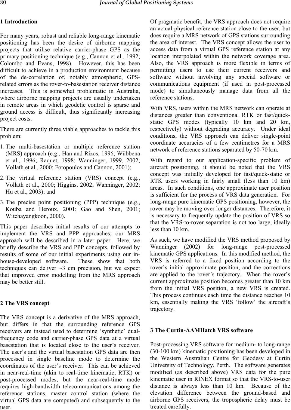 80 Journal of Global Positioning Systems 1 Introduction For many years, robust and reliable long-range kinematic positioning has been the desire of airborne mapping projects that utilise relative carrier-phase GPS as the primary positioning technique (e.g., Cannon et al., 1992; Colombo and Evans, 1998). However, this has been difficult to achieve in a production environment because of the de-correlation of, notably atmospheric, GPS- related errors as the rover-to-basestation receiver distance increases. This is somewhat problematic in Australia, where airborne mapping projects are usually undertaken in remote areas in which geodetic control is sparse and ground access is difficult, thus significantly increasing project costs. There are currently three viable approaches to tackle this problem: 1. The multi-basestation or multiple reference station (MRS) approach (e.g., Han and Rizos, 1996; Wübbena et al., 1996; Raquet, 1998; Wanninger, 1999, 2002; Vollath et al., 2000; Fotopoulos and Cannon, 2001); 2. The virtual reference station (VRS) concept (e.g., Vollath et al., 2000; Higgins, 2002; Wanninger, 2002; Hu et al., 2003); and 3. The precise point positioning (PPP) technique (e.g., Kouba and Heroux, 2001; Gao and Shen, 2001; Witchayangkoon, 2000). This paper describes initial results of our attempts to implement the VRS and PPP approaches; our MRS approach will be described in a later paper. Here, we briefly describe the VRS and PPP concepts, followed by results of some of our initial experiments using our in- house-developed software. These show that both techniques can deliver ~3 cm precision, but we expect that improved error modelling from the MRS approach may be better still. 2 The VRS concept The VRS concept is a derivative of the MRS approach, but differs in that the surrounding reference GPS receivers are instead used to determine ‘synthetic’ dual- frequency code and carrier-phase GPS data at a virtual basestation that is located close to the user’s receiver. The user’s and the virtual basestation GPS data are then processed in single baseline mode to determine the coordinates of the user’s receiver. This can be achieved in near-real-time (akin to real-time kinematic, RTK) or post-processed modes, but the near-real-time mode requires high-bandwidth telecommunications among the reference stations, master control station (where the virtual GPS data are computed) and subsequently to the user. Of pragmatic benefit, the VRS approach does not require an actual physical reference station close to the user, but does require a MRS network of GPS stations surrou nding the area of interest. The VRS concept allows the user to access data from a virtual GPS reference station at any location interpolated within the network coverage area. Also, the VRS approach is more flexible in terms of permitting users to use their current receivers and software without involving any special software or communications equipment (if used in post-processed mode) to simultaneously manage data from all the reference stations. With VRS, users within the MRS network can operate at distances greater than conventional RTK or fast/quick- static GPS modes (typically 10 km and 20 km, respectively) without degrading accuracy. Under ideal conditions, the VRS approach can deliver single-point coordinate accuracies of a few centimetres for a MRS network of re f e rence stations sepa rat e d by 50-70 km . With regard to our application-specific problem of aircraft positioning, it should be noted that the VRS concept was initially developed for fast/quick-static or RTK users working in fairly small (less than 10 km) areas. In such conditions, one approximate user position is sufficient for the process of VRS data generation. For long-range pure kinematic GPS positioning, however, the rover may be moving over longer distances. Therefore, it is necessary to frequently update the position of VRS so that the VRS-to-rover separation is not too large, ideally less than 10 km. As such, we have modified the VRS method proposed by Wanninger (2002) for long-range post-processed kinematic GPS applications. In this modified method, the VRS is referred to a fixed position according to the rover’s initial approximate position, and the corrections are applied to the rover’s trajectory. When the rover’s current approximate position becomes greater than 10 km from the initial VRS position, a new VRS is created. This process continues each time the distance reaches 10 km, essentially making the VRS ‘follow’ the aircraft’s trajectory. 3 The Curtin-AAMHatch VRS software Post-processing V RS software for medium- to long -range (30-100 km) kinematic positioning has been developed in the Western Australian Centre for Geodesy at Curtin University of Technology, Perth. The software generates modified (as described above) VRS data for the pure kinematic user in RINEX format so that the VRS-to-user distance is always less than 10 km. Because of the elevation difference between the ground-based and airborne GPS receivers, the tropospheric delay must be treated carefully. 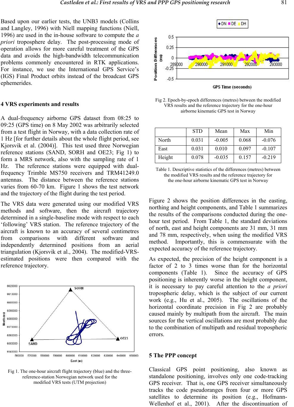 Castleden et al.: First results of VRS and PPP GPS positioning research 81 Based upon our earlier tests, the UNB3 models (Collins and Langley, 1996) with Niell mapping functions (Niell, 1996) are used in the in-house software to compute the a priori troposphere delay. The post-processing mode of operation allows for more careful treatment of the GPS data and avoids the high-bandwidth telecommunication problems commonly encountered in RTK applications. For instance, we use the International GPS Service’s (IGS) Final Product orbits instead of the broadcast GPS ephemeri des . 4 VRS experiments and results A dual-frequency airborne GPS dataset from 08:25 to 09:25 (GPS time) on 8 May 2002 was arbitrarily selected from a test flight in Norway, with a data collection rate of 1 Hz [for further details about the whole flight period, see Kjorsvik et al. (2004)]. This test used three Norwegian reference stations (SAND, SORH and OE23; Fig 1) to form a MRS network, also with the sampling rate of 1 Hz. The reference stations were equipped with dual- frequency Trimble MS750 receivers and TRM41249.0 antennas. The distance between the reference stations varies from 60-70 km. Figure 1 shows the test network and the trajectory of the flight during the test period. The VRS data were generated using our modified VRS methods and software, then the aircraft trajectory determined in a single-baseline mode with respect to each ‘following’ VRS station. The reference trajectory of the aircraft is known to an accuracy of several centimetres from comparisons with different software and independently determined positions from an aerial triangulation (Kjorsvik et al., 2004). The modified-VRS- estimated positions were then compared with the reference trajectory. Fig 1. The one-hour airc raft flight trajectory (blue) and the three- reference-station Norw eg i an n e tw o rk us ed fo r the modified VRS tests (UTM projection) Fig 2. Epoch-by- epoch differences (m et re s) between the modified VRS results and the reference trajectory for the one-hour airborne kinematic GPS test in Norway STD Mean Max Min North 0.031 -0.005 0.068 -0.076 East 0.031 0.010 0.097 -0.107 Height 0.078 -0.035 0.157 -0.219 Table 1. Descriptive statistics of the differences (metres) between the modified VRS results and the reference trajectory for the one-hour airborne kinematic GPS test in Norway Figure 2 shows the position differences in the easting, northing and height components, and Table 1 summarizes the results of the comparisons conducted during the one- hour test period. From Table 1, the standard deviations of north, east and height components are 31 mm, 31 mm and 78 mm, respectively, when using the modified VRS method. Importantly, this is commensurate with the expected accuracy of the reference trajectory. As expected, the precision of the height component is a factor of 2 to 3 times worse than for the horizontal components (Table 1). Since the accuracy of GPS positioning is inherently worse in the height component, it is necessary to pay careful attention to the a priori tropospheric delay, which is the subject of our current work (e.g., Hu et al., 2005). The oscillations of the horizontal coordinate precision in Fig 2 are probably caused mainly by multipath from the aircraft. The main sources for the vertical oscilla tions are most prob ably due to the combination of multip ath and residual tropospheric errors. 5 The PPP concept Classical GPS point positioning, also known as standalone positioning, involves only one code-tracking GPS receiver. That is, one GPS receiver simultaneously tracks the code pseudoranges from four or more GPS satellites to determine its position (e.g., Hofmann- Wellenhof et al., 2001). After the discontinuation of 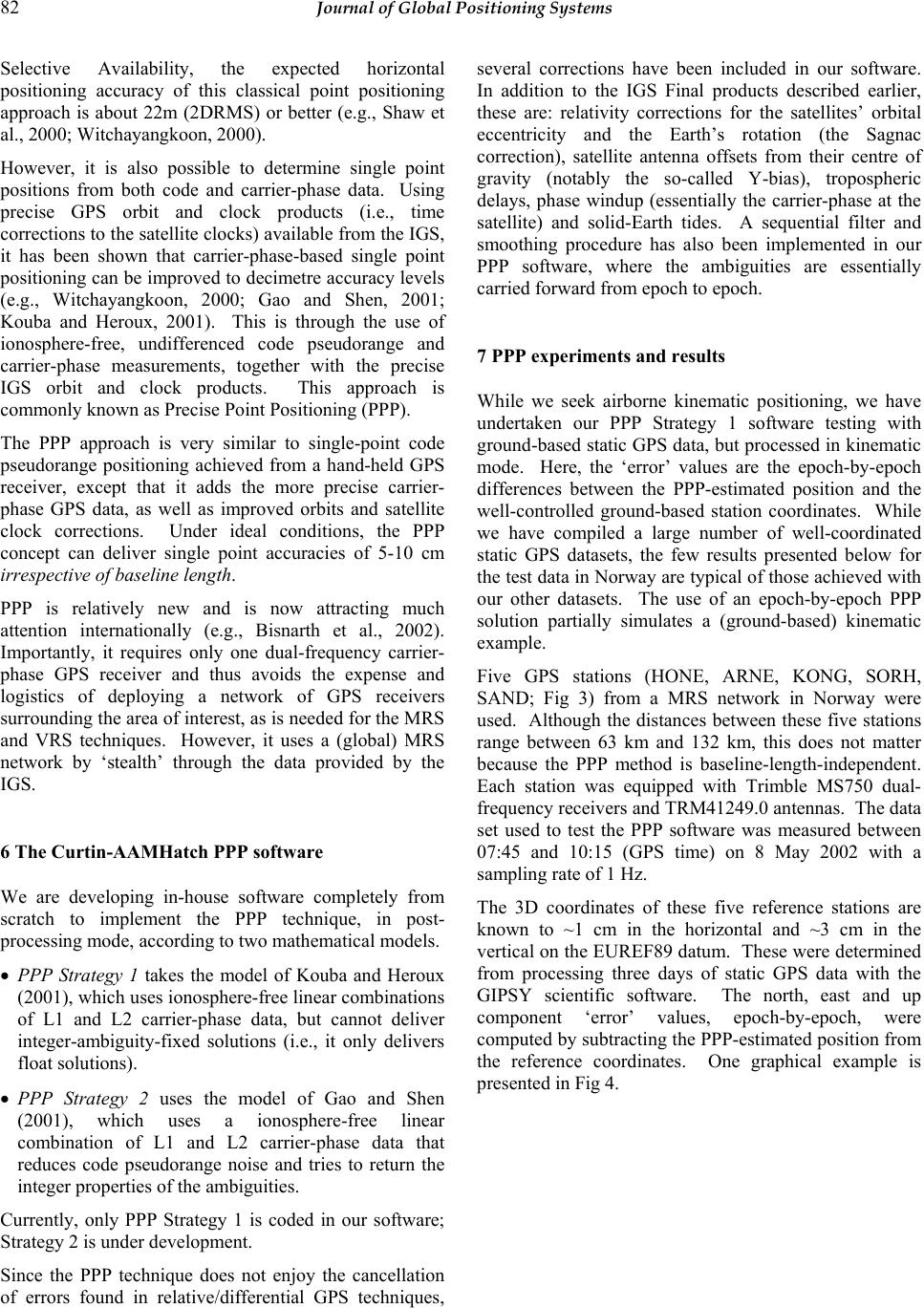 82 Journal of Global Positioning Systems Selective Availability, the expected horizontal positioning accuracy of this classical point positioning approach is about 22m (2DRMS) or better (e.g., Shaw et al., 2000; Witchayangkoon, 2000). However, it is also possible to determine single point positions from both code and carrier-phase data. Using precise GPS orbit and clock products (i.e., time corrections to the satellite clo cks) available fro m the IGS, it has been shown that carrier-phase-based single point positioning can be improved to decimetre accuracy lev els (e.g., Witchayangkoon, 2000; Gao and Shen, 2001; Kouba and Heroux, 2001). This is through the use of ionosphere-free, undifferenced code pseudorange and carrier-phase measurements, together with the precise IGS orbit and clock products. This approach is commonly known as Precise Point Positioning (PPP). The PPP approach is very similar to single-point code pseudorange positioning achieved from a hand-held GPS receiver, except that it adds the more precise carrier- phase GPS data, as well as improved orbits and satellite clock corrections. Under ideal conditions, the PPP concept can deliver single point accuracies of 5-10 cm irrespective of baseline length. PPP is relatively new and is now attracting much attention internationally (e.g., Bisnarth et al., 2002). Importantly, it requires only one dual-frequency carrier- phase GPS receiver and thus avoids the expense and logistics of deploying a network of GPS receivers surrounding the area of interest, as is needed for the MRS and VRS techniques. However, it uses a (global) MRS network by ‘stealth’ through the data provided by the IGS. 6 The Curtin-AAMHatch PPP software We are developing in-house software completely from scratch to implement the PPP technique, in post- processing mode, according to two mathematical models. • PPP Strategy 1 takes the model of Kouba and Heroux (2001), which uses ionosphere-free linear combination s of L1 and L2 carrier-phase data, but cannot deliver integer-ambiguity-fixed solutions (i.e., it only delivers float solutions). • PPP Strategy 2 uses the model of Gao and Shen (2001), which uses a ionosphere-free linear combination of L1 and L2 carrier-phase data that reduces code pseudorange noise and tries to return the integer properties of the ambiguities. Currently, only PPP Strategy 1 is coded in our software; Strategy 2 is under develo pm ent . Since the PPP technique does not enjoy the cancellation of errors found in relative/differential GPS techniques, several corrections have been included in our software. In addition to the IGS Final products described earlier, these are: relativity corrections for the satellites’ orbital eccentricity and the Earth’s rotation (the Sagnac correction), satellite antenna offsets from their centre of gravity (notably the so-called Y-bias), tropospheric delays, phase windup (essentially the carrier-phase at the satellite) and solid-Earth tides. A sequential filter and smoothing procedure has also been implemented in our PPP software, where the ambiguities are essentially carried forward from epoch to epoch. 7 PPP experiments and results While we seek airborne kinematic positioning, we have undertaken our PPP Strategy 1 software testing with ground-based static GPS data, but processed in kinematic mode. Here, the ‘error’ values are the epoch-by-epoch differences between the PPP-estimated position and the well-controlled ground-based station coordinates. While we have compiled a large number of well-coordinated static GPS datasets, the few results presented below for the test data in Norway are typical of those achieved with our other datasets. The use of an epoch-by-epoch PPP solution partially simulates a (ground-based) kinematic example. Five GPS stations (HONE, ARNE, KONG, SORH, SAND; Fig 3) from a MRS network in Norway were used. Although the distances between these five stations range between 63 km and 132 km, this does not matter because the PPP method is baseline-length-independent. Each station was equipped with Trimble MS750 dual- frequency receivers and TRM41249.0 antennas. The data set used to test the PPP software was measured between 07:45 and 10:15 (GPS time) on 8 May 2002 with a sampling rate of 1 Hz. The 3D coordinates of these five reference stations are known to ~1 cm in the horizontal and ~3 cm in the vertical on the EUREF89 datum. These were determined from processing three days of static GPS data with the GIPSY scientific software. The north, east and up component ‘error’ values, epoch-by-epoch, were computed by subtracting the PPP-estimated position from the reference coordinates. One graphical example is presented in Fi g 4.  Castleden et al.: First results of VRS and PPP GPS positioning research 83 Fig 3. The five-re fere n c e -station Norwegian network used for the PPP tests (0.1° ~ 11 km) Fig 4. Epoch-by-epoch differences (metres) between the PPP results and the known coordina t e s o f the static station KONG for t h e three-hour (sim ulated) kinematic GPS t est in Norway STD Mean Station North East Height North East Height KONG 0.028 0.048 0.074 0.036 -0.170 0.157 HONE 0.030 0.032 0.063 0.042 -0.198 0.034 ARNE 0.033 0.030 0.053 0.038 -0.128 -0.016 SORH 0.023 0.033 0.035 0.062 0.006 0.118 SAND 0.005 0.005 0.002 -0.008 -0.034 0.116 Table 2. Descriptive statistics of the differences (metres) between the PPP results and the known coordinates of the static stations for the three-hour (sim ulated) kinematic GPS t ests in Norway Table 2 summarises the PPP ‘error’ values for all five stations. It can be seen from Table 2 that the PPP Strategy 1 solutions achieve around 30 mm precisions for the north, east and height components in terms of standard deviations, but this depends on the GPS data quality from the stations. Curiou sly, the height errors are less than expected in some cases. 8 Concluding remarks We have presented some of our preliminary results for long-range kinematic GPS positioning using two post- processing software packages developed in-house at the Western Australian Centre for Geodesy. For the modified VRS software, test results using one-hour of 1 Hz real airborne kinematic GPS data in Norway show ~3 cm precision for the horizontal components and ~8 cm precision for the height component. For the PPP software, epoch-by-epoch static (i.e., simulated ground- based kinematic) test results using three hours of 1 Hz data in Norway indicate ~3 cm precision in all three coordinate components. While these results are extremely encouraging, and commensurate with studies conducted by other authors, we are now focussing on the post-processed MRS approach (e.g., Hu et al., 2005), which will allow the use of network constraints and improved (particularly atmospheric) error modelling. Acknowledgements: The Australian Research Council and AAMHatch Pty Ltd jointly fund this research References Bisnarth SN, Beran T, Lngley RB (2002) Precise platform positioning with a single GPS receiver, GPS World 13(4): 42-49. Cannon ME, Schwarz KP, Wei M (1992) A consistency test of airborne GPS using multiple monitor stations, Bulletin Géodésique 66(1): 2-11 Collins P, Langley R (1996) Limiting factors in tropospheric propagation delay error modelling for GPS airborne navigation. Proceedings of The Institute of Navigation 52nd Annual Meeting, 19–21 June, Cambridge, Massachusetts, USA, pp 519-528 Colombo OL, Evans AG (1998) Testing decimeter-level, kinematic, differential GPS over great distances at sea and on land, Proceedings of ION GPS 1998, 15-18 Sept, Nashville, Tennessee, USA, pp 1257-1264 Fotopoulos G, Cannon ME (2001) An overview of multi- reference station methods for cm-level positioning, GPS Solutions 4(3): 1-10 Gao Y, Shen X (2001) Improving ambiguity convergence in carrier phase-based precise point positioning. Proceedings of ION GPS 2001, 11-14 September, Salt Lake City, Utah, USA, pp 1532-1539  84 Journal of Global Positioning Systems Han S, Rizos C (1996) GPS network design and error mitigation for real-time continuous array monitoring system, Proceedings of ION GPS-1996, Sept 17-20, Kansas City, Missouri, USA, pp 1827-1836 Higgins MB (2002) Australia’s changing surveying infrastructure from marks in the ground to virtual reference stations. Proceedings of FIG XXII International Congress, April 19-26, Washington, USA, CD-ROM paper TS5.6 Hofmann-Wellenhof B, Lichtenegger H, Collins J (2001) Global positioning system: theory and practice. 5th edn. Springer, Vienna New York Hu GR, Khoo HS, Goh PC, Law CL (2003) Development and assessment of virtual reference stations for RTK positioning. Journal of Geodesy 77(5-6): 292-302 Hu G, Abbey DA, Castleden N, Featherstone WE, Earls CJ, Ovstedal O, Weihing D (2005) An approach for instantaneous ambiguity resolution for medium- to long- range multiple reference station networks. GPS Solutions 9(1):1-11 Kjorsvik N, Ovstedal O, Svendsen JGG (2004) Long range differential GNSS for positioning of airborne sensors. in: Sansò, F. (ed) A Window on the Future of Geodesy, Springer, Berlin Heidelberg New York (in press) Kouba J, Héroux P (2001) Precise Point Positioning using IGS orbit and clock products. GPS Solutions 5(2): 12-28 Niell AE (1996) Global mapping functions for the atmosphere delay at radio wavelengths. Journal of Geophysical Research 101(B2): 3227-3246 Raquet J (1998) Development of a method for kinematic GPS carrier phase ambiguity resolution using multiple reference receivers, UCGE report 20116, Dept of Geomatics, Univ of Calgary (http://www.geomatics.ucalgary.ca/gradtheses.html). Shaw M, Sandhoo K, Turner D (2000) Modernization of the Global Positioning System. GPS World 11(9): 36-44 Vollath U, Buecherl A, Landau H, Pagels C, Wagner B (2000) Multi-base RTK positioning using virtual reference stations. Proceedings of ION GPS-2000, 19-22 Sept, Salt Lake City, Utah, USA, pp 123-131 Wanninger L (1999) The performance of virtual reference stations in active geodetic GPS-networks under solar maximum conditions. Proceedings of ION GPS-1999, Nashville, Tennessee, USA, pp 1419-1427 Wanninger L (2002) Virtual reference stations for centimeter- level kinematic positioning, Proceedings of ION GPS- 2002, 24-27 Sept, Portland, Oregon, USA, pp 1400-1407 Witchayangkoon B (2000). Elements of GPS Precise Point Positioning. Ph.D. dissertation, Dept of Spatial Information Science and Engineering, Univ of Maine, USA, 265 pp Wübbena G, Bagge A, Seeber G, Böder V, Hankemeier P (1996) Reducing distance dependent errors for real-time precise DGPS applications by establishing reference station networks. Proceedings of ION GPS-1996, Sept 17- 20, Kansas City, Missouri, USA, pp 1845-1852 |