Paper Menu >>
Journal Menu >>
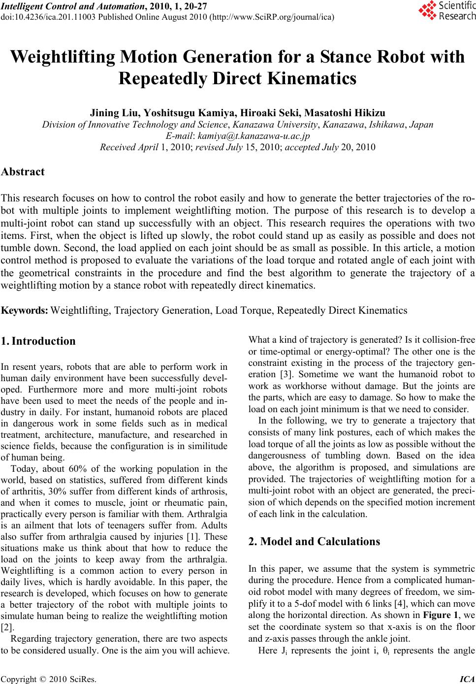 Intelligent Control and Automation, 2010, 1, 20-27 doi:10.4236/ica.201.11003 Published Online August 2010 (http://www.SciRP.org/journal/ica) Copyright © 2010 SciRes. ICA Weightlifting Motion Generation for a Stance Robot with Repeatedly Direct Kinematics Jining Liu, Yoshitsugu Kamiya, Hiroaki Seki, Masatoshi Hikizu Division of Innovative Technology and Science, Kanazawa University, Kanazawa, Ishikawa, Japan E-mail: kamiya@t.kanazawa-u.ac.jp Received April 1, 2010; revised July 15, 2010; accepted July 20, 2010 Abstract This research focuses on how to control the robot easily and how to generate the better trajectories of the ro- bot with multiple joints to implement weightlifting motion. The purpose of this research is to develop a multi-joint robot can stand up successfully with an object. This research requires the operations with two items. First, when the object is lifted up slowly, the robot could stand up as easily as possible and does not tumble down. Second, the load applied on each joint should be as small as possible. In this article, a motion control method is proposed to evaluate the variations of the load torque and rotated angle of each joint with the geometrical constraints in the procedure and find the best algorithm to generate the trajectory of a weightlifting motion by a stance robot with repeatedly direct kinematics. Keywords: Weightlifting, Trajectory Generation, Load Torque, Repeatedly Direct Kinematics 1. Introduction In resent years, robots that are able to perform work in human daily environment have been successfully devel- oped. Furthermore more and more multi-joint robots have been used to meet the needs of the people and in- dustry in daily. For instant, humanoid robots are placed in dangerous work in some fields such as in medical treatment, architecture, manufacture, and researched in science fields, because the configuration is in similitude of human being. Today, about 60% of the working population in the world, based on statistics, suffered from different kinds of arthritis, 30% suffer from different kinds of arthrosis, and when it comes to muscle, joint or rheumatic pain, practically every person is familiar with them. Arthralgia is an ailment that lots of teenagers suffer from. Adults also suffer from arthralgia caused by injuries [1]. These situations make us think about that how to reduce the load on the joints to keep away from the arthralgia. Weightlifting is a common action to every person in daily lives, which is hardly avoidable. In this paper, the research is developed, which focuses on how to generate a better trajectory of the robot with multiple joints to simulate human being to realize the weightlifting motion [2]. Regarding trajectory generation, there are two aspects to be considered usually. One is the aim you will achieve. What a kind of trajectory is generated? Is it collision-free or time-optimal or energy-optimal? The other one is the constraint existing in the process of the trajectory gen- eration [3]. Sometime we want the humanoid robot to work as workhorse without damage. But the joints are the parts, which are easy to damage. So how to make the load on each joint minimum is that we need to consider. In the following, we try to generate a trajectory that consists of many link postures, each of which makes the load torque of all the joints as low as possible without the dangerousness of tumbling down. Based on the idea above, the algorithm is proposed, and simulations are provided. The trajectories of weightlifting motion for a multi-joint robot with an object are generated, the preci- sion of which depends on the specified motion increment of each link in the calculation. 2. Model and Calculations In this paper, we assume that the system is symmetric during the procedure. Hence from a complicated human- oid robot model with many degrees of freedom, we sim- plify it to a 5-dof model with 6 links [4], which can move along the horizontal direction. As shown in Figure 1, we set the coordinate system so that x-axis is on the floor and z-axis passes through the ankle joint. Here Ji represents the joint i, θi represents the angle 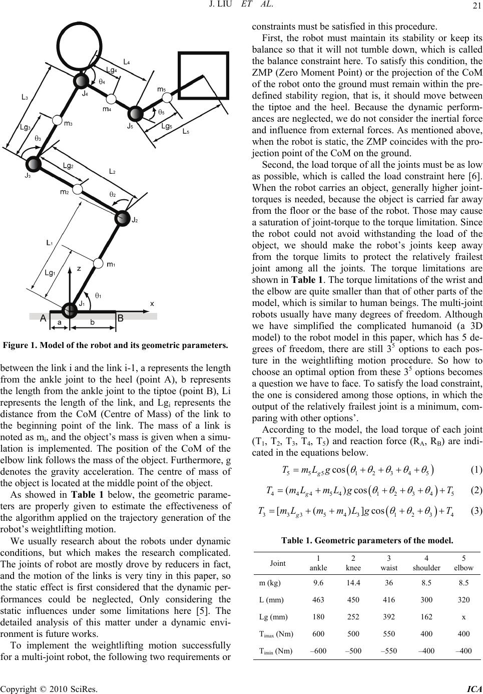 J. LIU ET AL. Copyright © 2010 SciRes. ICA 21 Figure 1. Model of the robot and its geometric parameters. between the link i and the link i-1, a represents the length from the ankle joint to the heel (point A), b represents the length from the ankle joint to the tiptoe (point B), Li represents the length of the link, and Lgi represents the distance from the CoM (Centre of Mass) of the link to the beginning point of the link. The mass of a link is noted as mi, and the object’s mass is given when a simu- lation is implemented. The position of the CoM of the elbow link follows the mass of the object. Furthermore, g denotes the gravity acceleration. The centre of mass of the object is located at the middle point of the object. As showed in Table 1 below, the geometric parame- ters are properly given to estimate the effectiveness of the algorithm applied on the trajectory generation of the robot’s weightlifting motion. We usually research about the robots under dynamic conditions, but which makes the research complicated. The joints of robot are mostly drove by reducers in fact, and the motion of the links is very tiny in this paper, so the static effect is first considered that the dynamic per- formances could be neglected, Only considering the static influences under some limitations here [5]. The detailed analysis of this matter under a dynamic envi- ronment is future works. To implement the weightlifting motion successfully for a multi-joint robot, the following two requirements or constraints must be satisfied in this procedure. First, the robot must maintain its stability or keep its balance so that it will not tumble down, which is called the balance constraint here. To satisfy this condition, the ZMP (Zero Moment Point) or the projection of the CoM of the robot onto the ground must remain within the pre- defined stability region, that is, it should move between the tiptoe and the heel. Because the dynamic perform- ances are neglected, we do not consider the inertial force and influence from external forces. As mentioned above, when the robot is static, the ZMP coincides with the pro- jection point of the CoM on the ground. Second, the load torque of all the joints must be as low as possible, which is called the load constraint here [6]. When the robot carries an object, generally higher joint- torques is needed, because the object is carried far away from the floor or the base of the robot. Those may cause a saturation of joint-torque to the torque limitation. Since the robot could not avoid withstanding the load of the object, we should make the robot’s joints keep away from the torque limits to protect the relatively frailest joint among all the joints. The torque limitations are shown in Table 1. The torque limitations of the wrist and the elbow are quite smaller than that of other parts of the model, which is similar to human beings. The multi-joint robots usually have many degrees of freedom. Although we have simplified the complicated humanoid (a 3D model) to the robot model in this paper, which has 5 de- grees of freedom, there are still 35 options to each pos- ture in the weightlifting motion procedure. So how to choose an optimal option from these 35 options becomes a question we have to face. To satisfy the load constraint, the one is considered among those options, in which the output of the relatively frailest joint is a minimum, com- paring with other options’. According to the model, the load torque of each joint (T1, T2, T3, T4, T5) and reaction force (RA, RB) are indi- cated in the equations below. 5 5512345 cos g TmLg (1) 44454 12345 ()cos g TmLmLg T (2) 333543 1234 [()]cos g TmL mmLgT (3) Table 1. Geometric parameters of the model. Joint 1 ankle 2 knee 3 waist 4 shoulder 5 elbow m (kg) 9.6 14.4 36 8.5 8.5 L (mm) 463 450 416 300 320 Lg (mm) 180 252 392 162 x Timax (Nm) 600 500 550 400 400 Timin (Nm) –600 –500 –550 –400 –400 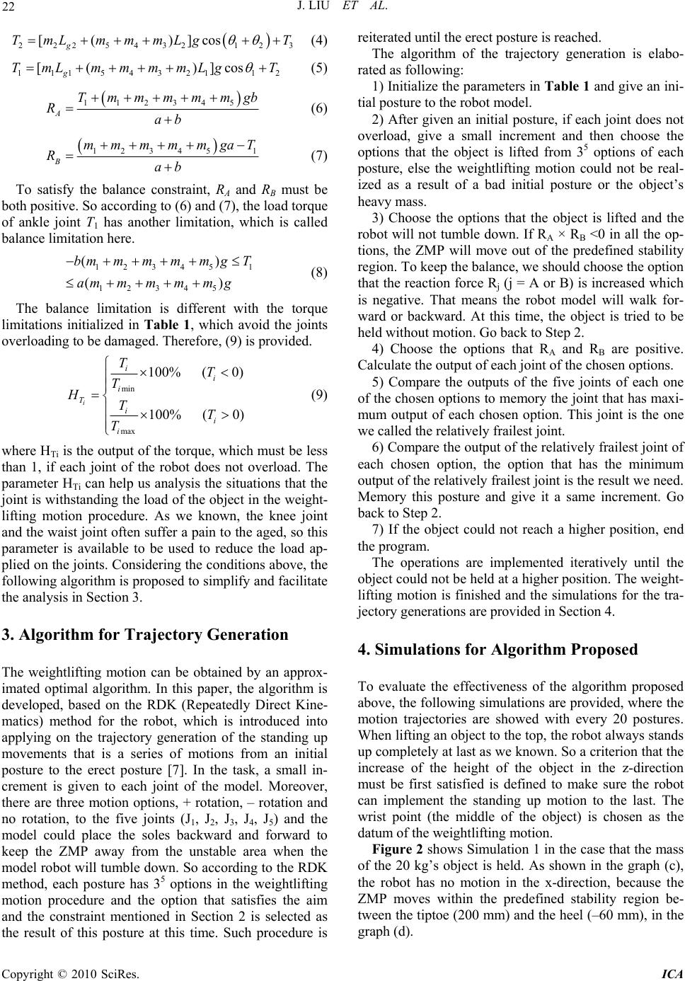 J. LIU ET AL. Copyright © 2010 SciRes. ICA 22 2225432 123 [( )]cos g TmL mmmLgT (4) 1 115432112 [( )]cos g TmL mmmmLgT (5) 1 12345 A T mmmmmgb Rab (6) 12345 1 B mm mm mgaT Rab (7) To satisfy the balance constraint, RA and RB must be both positive. So according to (6) and (7), the load torque of ankle joint T1 has another limitation, which is called balance limitation here. 12345 1 12345 () () bmmmmmgT ammmmmg (8) The balance limitation is different with the torque limitations initialized in Table 1, which avoid the joints overloading to be damaged. Therefore, (9) is provided. min max 100% (0) 100% (0) i i i i T i i i TT T HTT T (9) where HTi is the output of the torque, which must be less than 1, if each joint of the robot does not overload. The parameter HTi can help us analysis the situations that the joint is withstanding the load of the object in the weight- lifting motion procedure. As we known, the knee joint and the waist joint often suffer a pain to the aged, so this parameter is available to be used to reduce the load ap- plied on the joints. Considering the conditions above, the following algorithm is proposed to simplify and facilitate the analysis in Section 3. 3. Algorithm for Trajectory Generation The weightlifting motion can be obtained by an approx- imated optimal algorithm. In this paper, the algorithm is developed, based on the RDK (Repeatedly Direct Kine- matics) method for the robot, which is introduced into applying on the trajectory generation of the standing up movements that is a series of motions from an initial posture to the erect posture [7]. In the task, a small in- crement is given to each joint of the model. Moreover, there are three motion options, + rotation, – rotation and no rotation, to the five joints (J1, J2, J3, J4, J5) and the model could place the soles backward and forward to keep the ZMP away from the unstable area when the model robot will tumble down. So according to the RDK method, each posture has 35 options in the weightlifting motion procedure and the option that satisfies the aim and the constraint mentioned in Section 2 is selected as the result of this posture at this time. Such procedure is reiterated until the erect posture is reached. The algorithm of the trajectory generation is elabo- rated as following: 1) Initialize the parameters in Table 1 and give an ini- tial posture to the robot model. 2) After given an initial posture, if each joint does not overload, give a small increment and then choose the options that the object is lifted from 35 options of each posture, else the weightlifting motion could not be real- ized as a result of a bad initial posture or the object’s heavy mass. 3) Choose the options that the object is lifted and the robot will not tumble down. If RA × RB <0 in all the op- tions, the ZMP will move out of the predefined stability region. To keep the balance, we should choose the option that the reaction force Rj (j = A or B) is increased which is negative. That means the robot model will walk for- ward or backward. At this time, the object is tried to be held without motion. Go back to Step 2. 4) Choose the options that RA and RB are positive. Calculate the output of each joint of the chosen options. 5) Compare the outputs of the five joints of each one of the chosen options to memory the joint that has maxi- mum output of each chosen option. This joint is the one we called the relatively frailest joint. 6) Compare the output of the relatively frailest joint of each chosen option, the option that has the minimum output of the relatively frailest joint is the result we need. Memory this posture and give it a same increment. Go back to Step 2. 7) If the object could not reach a higher position, end the program. The operations are implemented iteratively until the object could not be held at a higher position. The weight- lifting motion is finished and the simulations for the tra- jectory generations are provided in Section 4. 4. Simulations for Algorithm Proposed To evaluate the effectiveness of the algorithm proposed above, the following simulations are provided, where the motion trajectories are showed with every 20 postures. When lifting an object to the top, the robot always stands up completely at last as we known. So a criterion that the increase of the height of the object in the z-direction must be first satisfied is defined to make sure the robot can implement the standing up motion to the last. The wrist point (the middle of the object) is chosen as the datum of the weightlifting motion. Figure 2 shows Simulation 1 in the case that the mass of the 20 kg’s object is held. As shown in the graph (c), the robot has no motion in the x-direction, because the ZMP moves within the predefined stability region be- tween the tiptoe (200 mm) and the heel (–60 mm), in the graph (d).  J. LIU ET AL. Copyright © 2010 SciRes. ICA 23 (a) (b) (c) (d) (e) (f) (g) Figure 2. Simulation 1 of weightlifting. (a) (b) (c) (d) (e) (f) (g) Figure 3. Simulation 2 of weightlifting. 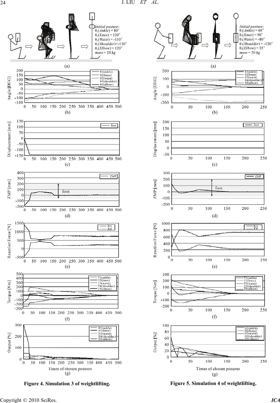 J. LIU ET AL. Copyright © 2010 SciRes. ICA 24 (a) (b) (c) (d) (e) (f) (g) Figure 4. Simulation 3 of weightlifting. (a) (b) (c) (d) (e) (f) (g) Figure 5. Simulation 4 of weightlifting. 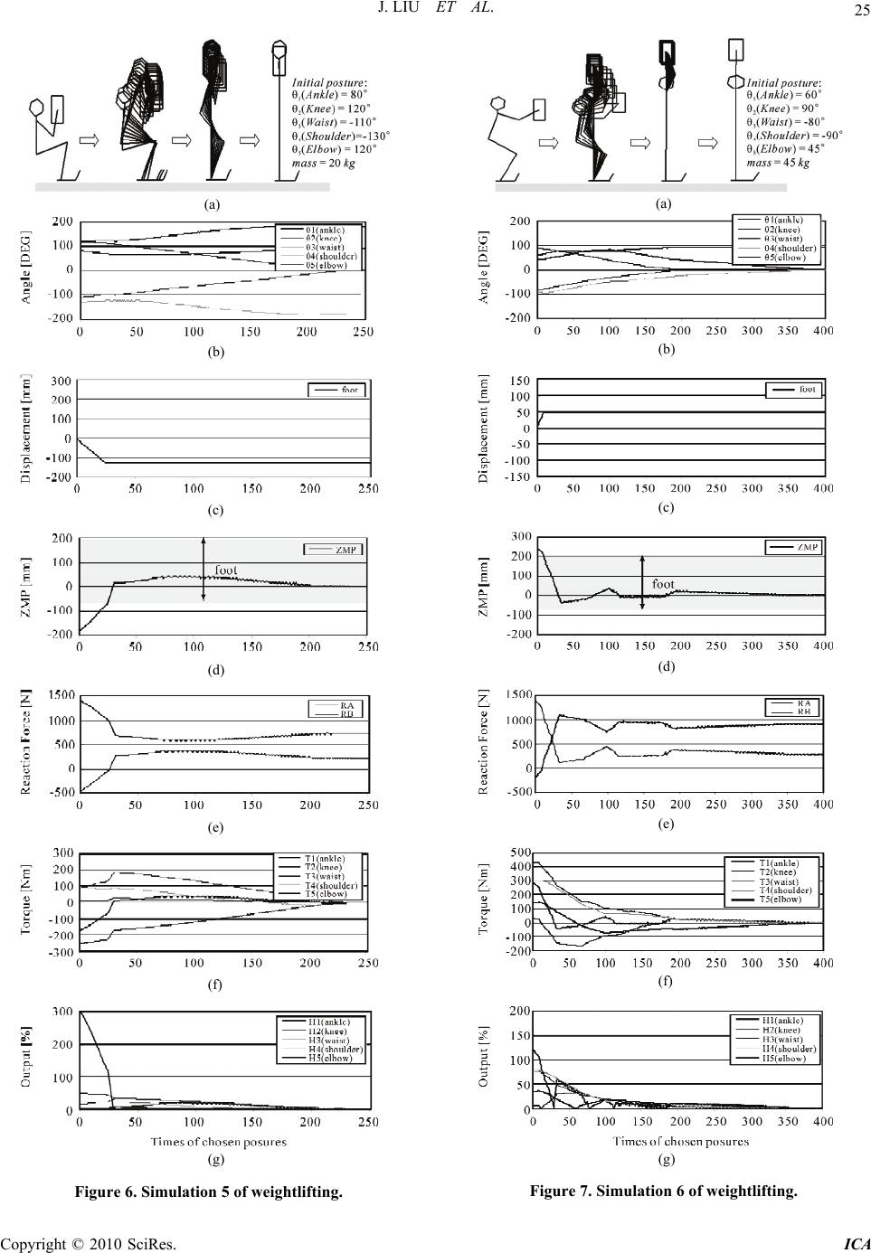 J. LIU ET AL. Copyright © 2010 SciRes. ICA 25 (a) (b) (c) (d) (e) (f) (g) Figure 6. Simulation 5 of weightlifting. (a) (b) (c) (d) (e) (f) (g) Figure 7. Simulation 6 of weightlifting.  J. LIU ET AL. Copyright © 2010 SciRes. ICA 26 The graph (b) shows the change of the joint angle with the posture. According to graph (b), we can obtain that when the object is lifted to the top, the robot has stood up completely and stretched its arm, where the angle of the ankle joint approximates to 90°, the ones of other joints approximate to 0°, just like human being. The reaction forces are always positive in the graph (e) indicates that the robot is stable without no displacement in each direc- tion, just as shown in the graph (c), which is satisfying the balance constraint. The graph (f) shows the change of the joint torque with the posture. We can see in the graph (g) that the outputs of all joints are within the limits, meaning that it never reaches saturation when lifting the object. Here, we want to explain that the output of the ankle joint is calculated for the balance limitation, when it is bigger than the load limitation. Finally, the weight- lifting motion is finished successfully. Simulation 2 has a same initial posture with the simu- lation 1, but the mass of the object is different, 45 kg. Because of the initial condition, as shown in the graph (d) of Figure 3, in the beginning stage, the ZMP is in front of the tiptoe (200 mm). So the robot moves forward (in the graph (c)) to avoid tumbling until the position of the ZMP enters into the stability region. At this time, the value of the reaction force RA changes from negative to positive in the graph (e). The graph (f) shows the change of the joint torque with the posture. In the graph (g), we can see that the output of the ankle joint is more than 1 at the beginning, meaning that the robot will tumble down. After ZMP entering into the stable area, the weightlifting motion is finished. Simulation 3 has a different initial posture from the simulation 1, but the mass of the object is same. Because of the initial condition, as shown in the graph (d) of Fig- ure 3, in the beginning stage, the ZMP is behind the heel (–60mm), meaning that the ZMP moves out of the pre- defined stability region. So the robot moves backward (in the graph (c)) to avoiding tumbling backward until the position of the ZMP enters into the stability region. Meanwhile, the value of the reaction force RB changes from negative to positive in the graph (e). The graph (f) shows the change of the joint torque with the posture. In the graph (g), we can see that the output of the ankle joint is more than 1 at the beginning, meaning that the load torque that the ankle joint withstands has exceeded the balance torque limitation. After ZMP entering into the stable area, the weightlifting motion is finished. With the same algorithm, the Simulation 4~6 are pro- vided that we choose the shoulder joint as the datum to evaluate the whole weightlifting motion, where the rise of the shoulder must be first considered. In these simula- tions, we still take the load constraint and balance con- straint into account to implement the weightlifting mo- tion. Figure 5 shows Simulation 4 in the case that the mass of the 20 kg’s object is held. The robot has no motion in the x-direction, because the ZMP moves within the pre- defined stability region. Finally, the trajectory of the mo- tion is generated where the object is held around the waist joint, like a person lifting up a water bucket. Al- though Simulation 5 and Simulation 3 are implemented under a same initial condition, the trajectory generations are different because of the different datum. And the end position of the object is not always located on the top. Simulation 6 and Simulation 2 are implemented under a same initial condition, even though the trajectory genera- tions are different, we still realize the weightlifting mo- tion to hold the object at the highest spot. It is similar with human being that the robot cannot always lift up any object, if the object is too heavy for the robot. For example, in the Simulation 1, the robot can lift up 20 kg’s object easily. But in the Simulation 2, the robot has to move forward not to tumble with 45 kg’s object, and if the mass of the object is more than 50 kg, the robot cannot implement the weightlifting motion. At this time, the load torque of the knee joint exceeds the torque limitation showed in Table 1, so the robot cannot stand up with the object as usual, unless the torque limi- tation of the knee joint is enlarged. All these results show that our proposed algorithm of weightlifting motion is effective. 5. Conclusions In this paper, we realized the weightlifting motion suc- cessfully with the multi-joint robot model under some predefined conditions. The trajectory of a lift-up motion for a stance robot is also generated by RDK method. We proposed the algorithm with considering the output of the joint to reduce the load on the joint to protect the relatively frailest joint. According to simulations, we verified the rationality and the effectiveness of the pro- posed algorithm. We also hope that this paper can con- tribute the research about the configuration of humanoid robot or human being and helping the aged and the handicapped in daily. This method based on RDK method is used to obtain a continuous trajectory generation, which is under the static environment. In the future, the dynamic influence will be considered. 6. References [1] Japan Industrial Safety and Health Association, “Investi- gation Research on Development of the Evaluation Crite- ria of the Work Load Considering Advanced Age La- bourers’ Safety and Health-The Heisei 13 fiscal year re- port,” Japanese, 2001. [2] N. Miyata, “Individual Human Motion Performance In- dex to Generate Lift-up Motion,” Proceedings of the 19th Annual Conference of the Robotics Society of Japan  J. LIU ET AL. Copyright © 2010 SciRes. ICA 27 (RSJ2001), Tokyo, 2001, pp. 721-742. [3] E. Bayo and B. Paden, “On Trajectory Generation for Flexible Robots,” Journal of Robotic Systems, Vol. 4, No. 2, 1987, pp 229-235. [4] L. Song, Y. Kamiya, H. Seki, S. M. Hikizu and Q. Zhang, “Solutions of Inverse Kinematics of Articulated Robot by Using Repeatedly Direct Kinematics,” Journal of the Ja- pan Society for Precision Engineering, Vol. 67, No. 6, 2001, pp 971-976. [5] R. Kamnik: “Standing-Up Robot,” Journal of Medical Engineering & Technology, Vol. 28, No. 2, 2004, pp. 74- 80. [6] T. Matsumaru, S. Fukuyama and T. Sato, “Model for Analysis of Weight Lifting Motion Considering the Ab- dominal Pressure Increased by Valsalva Maneuver,” Transactions of the Japan Society of Mechanical Engi- neers (Series C), Vol. 72, No. 724, 2006, pp 169-176. [7] Y. Kamiya, T. Kubo, S. Aoyagi and S. Okabe, “Control of Robotic Manipulators Using the Solutions of Repeated Direct Kinematics,” Transactions of the Japan Society of Mechanical Engineers (Series C), Vol. 59, No. 564, 1993, pp 125-130. |