Paper Menu >>
Journal Menu >>
 Journal of Global Positioning Systems (2004) Vol. 3, No. 1-2: 49-56 Benefits of a Reconfigurable Software GNSS Receiver in Multipath Environment Fabio Dovis, Marco Pini, Massimiliano Spelat Politecnico di Torino, Corso Duca degli Abruzzi 24, 10129 Torino, Italy Tel: +39 011 2276 415 Fax: +39 011 564 4099 Email: name.surname@polito.it Paolo Mulassano Istituto Superiore Mario Boella (ISMB), Via P. Boggio 61, 10138 Torino, Italy Tel: +39 011 2276 414 Fax: +39 011 2276 299 Email: paolo.mulassano@ismb.it Received: / Accepted: 15 November 2004 / Accepted: 3 February 2005 Abstract. The increased interest for applications based on both navigation and communication systems, represents an important driver for the design and implementation of innovative receivers architectures. The realization of civil GPS applications, the advent of the European navigation system Galileo, and the integration of localization services in communication network make the reconfigurability an indispensable requirement for the development of innovative Global Navigation Satellite Systems (GNSS) platforms. In addition, it must be pointed out that several problem as indoor positioning and multipath recovery, are pushing the research activity in order to provide users of flexible devices able to adapt their functionalities according to the environment. Considering this complex scenario, the Software Defined Radio (SDR) approach constitutes an interesting perspective to develop modular architectures. In this paper, the implementation of a reconfigurable user terminal integrating both navigation and communication capabilities will be discussed. The work will be presented focusing the attention on software-designed functionalities and the Navigation Unit will be analyzed and tested. An example of adaptability of the receiver to the operating environment will be presented. The reconfigurable module for multipath mitigation in the tracking phase will be described with particular attention to the implementation aspect, and some simulation results will be presented. Keywords. GNSS Receiver, Software Defined Radio, Reconfigurability, Multipath. 1 Introduction Satellite navigation, positioning and timing has already found widespread applications in a large variety of fields. It is well known that the GNSS programme has given an important contribution to the research activity, and in particular on topics based on the development of user terminals. The European Galileo project constitutes, for the next decade, an essential contribution to the satellite navigation market. In this context, it has to be remarked that in addition to the realization of basic system segments, a relevant effort is being devoted to the design of Local Elements (LE) for providing assistance data to users in the coverage area. As a direct consequence, the study and design of advanced terminals able to deal with both the Signal-In-Space (SIS) and other classes of signals transmitted by stations and satellite augmentations (EGNOS), become indispensable. In particular, it is expected that at the LE level, User Terminal (UT) will have to deal with the innovative Location Based Services that are being developed for the cellular network, with particular attention to emergency services (e.g. the European emergency number E-112). At the same time, the GPS Joint Program Office has launched the “Modernization Phase”, which consists in the study of new frequencies and spreading codes for additional military and civil signals. Given these innovations, a civil user will receive additional SIS for improving accuracy, integrity and continuity of services; on the other hand, military users will increase the security with a shorter time to first fix and a faster signal acquisition procedure. Considering this complex scenario, flexibility represents an essential feature for the UTs. This peculiarity can be 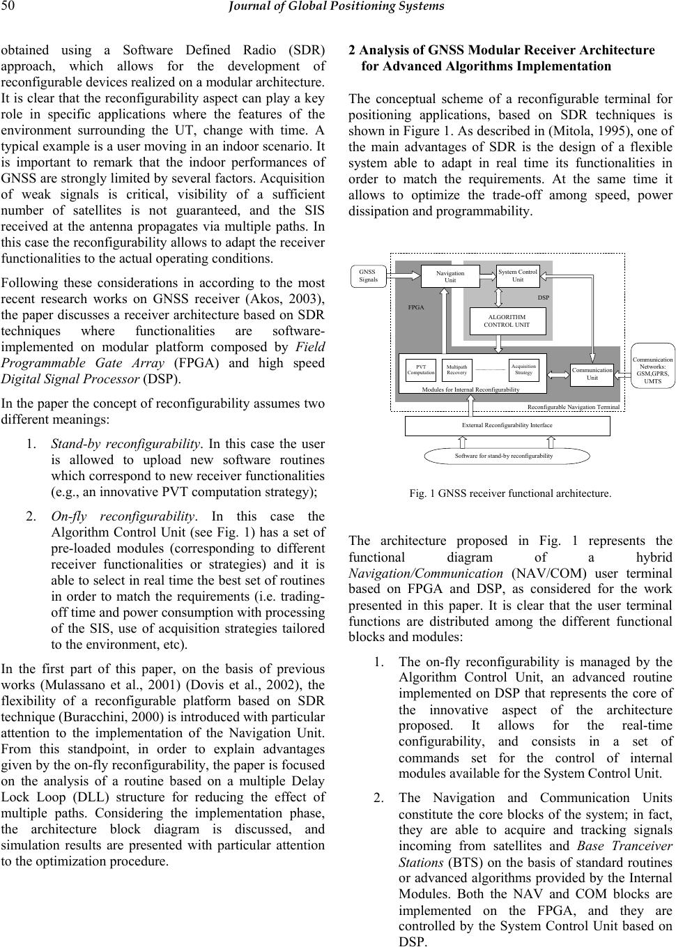 50 Journal of Global Positioning Systems obtained using a Software Defined Radio (SDR) approach, which allows for the development of reconfigurable devices realized on a modular architecture. It is clear that the reconfigurability aspect can play a key role in specific applications where the features of the environment surrounding the UT, change with time. A typical example is a user moving in an indoor scenario. It is important to remark that the indoor performances of GNSS are strongly limited by several factors. Acquisition of weak signals is critical, visibility of a sufficient number of satellites is not guaranteed, and the SIS received at the antenna propagates via multiple paths. In this case the reconfigurability allows to adapt the receiver functionalities to the actual operating conditions. Following these considerations in according to the most recent research works on GNSS receiver (Akos, 2003), the paper discusses a receiver architecture based on SDR techniques where functionalities are software- implemented on modular platform composed by Field Programmable Gate Array (FPGA) and high speed Digital Signal Processor (DSP). In the paper the concept of reconfigurability assumes two different meanings: 1. Stand-by reconfigurability. In this case the user is allowed to upload new software routines which correspond to new receiver functionalities (e.g., an innovative PVT computation strategy); 2. On-fly reconfigurability. In this case the Algorithm Control Unit (see Fig. 1) has a set of pre-loaded modules (corresponding to different receiver functionalities or strategies) and it is able to select in real time the best set of routines in order to match the requirements (i.e. trading- off time and power consumption with processing of the SIS, use of acquisition strategies tailored to the environment, etc). In the first part of this paper, on the basis of previous works (Mulassano et al., 2001) (Dovis et al., 2002), the flexibility of a reconfigurable platform based on SDR technique (Buracchini, 2000) is introduced with particular attention to the implementation of the Navigation Unit. From this standpoint, in order to explain advantages given by the on-fly reconfigurability, the paper is focused on the analysis of a routine based on a multiple Delay Lock Loop (DLL) structure for reducing the effect of multiple paths. Considering the implementation phase, the architecture block diagram is discussed, and simulation results are presented with particular attention to the optimization procedure. 2 Analysis of GNSS Modular Receiver Architecture for Advanced Algorithms Implementation The conceptual scheme of a reconfigurable terminal for positioning applications, based on SDR techniques is shown in Figure 1. As described in (Mitola, 1995), one of the main advantages of SDR is the design of a flexible system able to adapt in real time its functionalities in order to match the requirements. At the same time it allows to optimize the trade-off among speed, power dissipation and programmability. Navigation Unit System Control Unit Communication Unit GNSS Signals Communication Networks: GSM,GPRS, UMTS ALGORITHM CONTROL UNIT PVT Computation Multipath Recovery Modules for Internal Reconfigurability Acquisition Strategy Reconfigurable Navigation Terminal External Reconfigurability Interface DSP FPGA Software for stand-by reconfigurability Fig. 1 GNSS receiver functional architecture. The architecture proposed in Fig. 1 represents the functional diagram of a hybrid Navigation/Communication (NAV/COM) user terminal based on FPGA and DSP, as considered for the work presented in this paper. It is clear that the user terminal functions are distributed among the different functional blocks and modules: 1. The on-fly reconfigurability is managed by the Algorithm Control Unit, an advanced routine implemented on DSP that represents the core of the innovative aspect of the architecture proposed. It allows for the real-time configurability, and consists in a set of commands set for the control of internal modules available for the System Control Unit. 2. The Navigation and Communication Units constitute the core blocks of the system; in fact, they are able to acquire and tracking signals incoming from satellites and Base Tranceiver Stations (BTS) on the basis of standard routines or advanced algorithms provided by the Internal Modules. Both the NAV and COM blocks are implemented on the FPGA, and they are controlled by the System Control Unit based on DSP. 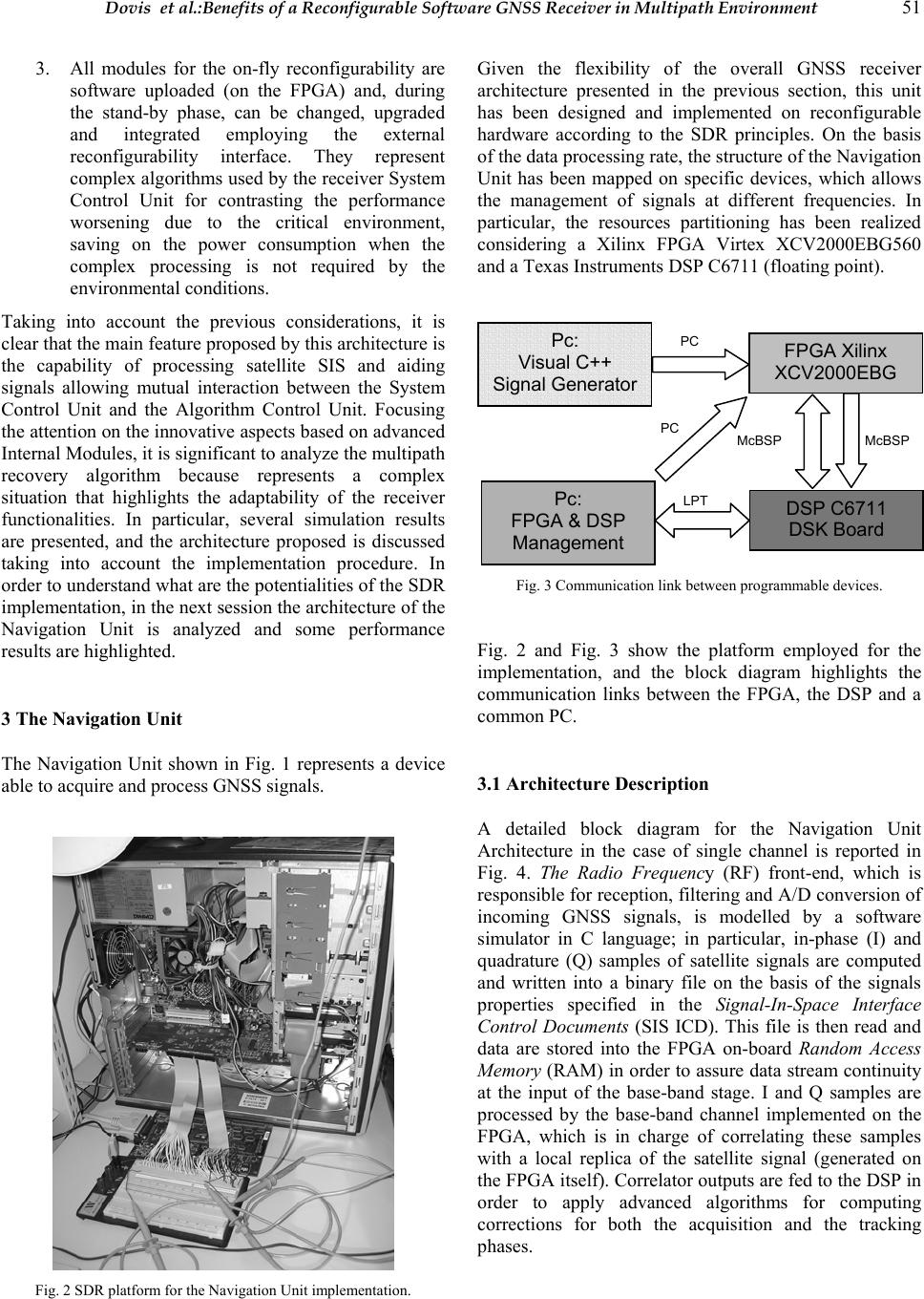 Dovis et al.:Benefits of a Reconfigurable Software GNSS Receiver in Multipath Environment 51 3. All modules for the on-fly reconfigurability are software uploaded (on the FPGA) and, during the stand-by phase, can be changed, upgraded and integrated employing the external reconfigurability interface. They represent complex algorithms used by the receiver System Control Unit for contrasting the performance worsening due to the critical environment, saving on the power consumption when the complex processing is not required by the environmental conditions. Taking into account the previous considerations, it is clear that the main feature proposed by this architecture is the capability of processing satellite SIS and aiding signals allowing mutual interaction between the System Control Unit and the Algorithm Control Unit. Focusing the attention on the innovative aspects based on advanced Internal Modules, it is significant to analyze the multipath recovery algorithm because represents a complex situation that highlights the adaptability of the receiver functionalities. In particular, several simulation results are presented, and the architecture proposed is discussed taking into account the implementation procedure. In order to understand what are the potentialities of the SDR implementation, in the next session the architecture of the Navigation Unit is analyzed and some performance results are highlighted. 3 The Navigation Unit The Navigation Unit shown in Fig. 1 represents a device able to acquire and process GNSS signals. Fig. 2 SDR platform for the Navigation Unit implementation. Given the flexibility of the overall GNSS receiver architecture presented in the previous section, this unit has been designed and implemented on reconfigurable hardware according to the SDR principles. On the basis of the data processing rate, the structure of the Navigation Unit has been mapped on specific devices, which allows the management of signals at different frequencies. In particular, the resources partitioning has been realized considering a Xilinx FPGA Virtex XCV2000EBG560 and a Texas Instruments DSP C6711 (floating point). Fig. 3 Communication link between programmable devices. Fig. 2 and Fig. 3 show the platform employed for the implementation, and the block diagram highlights the communication links between the FPGA, the DSP and a common PC. 3.1 Architecture Description A detailed block diagram for the Navigation Unit Architecture in the case of single channel is reported in Fig. 4. The Radio Frequency (RF) front-end, which is responsible for reception, filtering and A/D conversion of incoming GNSS signals, is modelled by a software simulator in C language; in particular, in-phase (I) and quadrature (Q) samples of satellite signals are computed and written into a binary file on the basis of the signals properties specified in the Signal-In-Space Interface Control Documents (SIS ICD). This file is then read and data are stored into the FPGA on-board Random Access Memory (RAM) in order to assure data stream continuity at the input of the base-band stage. I and Q samples are processed by the base-band channel implemented on the FPGA, which is in charge of correlating these samples with a local replica of the satellite signal (generated on the FPGA itself). Correlator outputs are fed to the DSP in order to apply advanced algorithms for computing corrections for both the acquisition and the tracking phases. Pc: Visual C++ Signal Generator FPGA Xilinx XCV2000EBG Pc: FPGA & DSP Management DSP C6711 DSK Board PC PC McBSP McBSP LPT 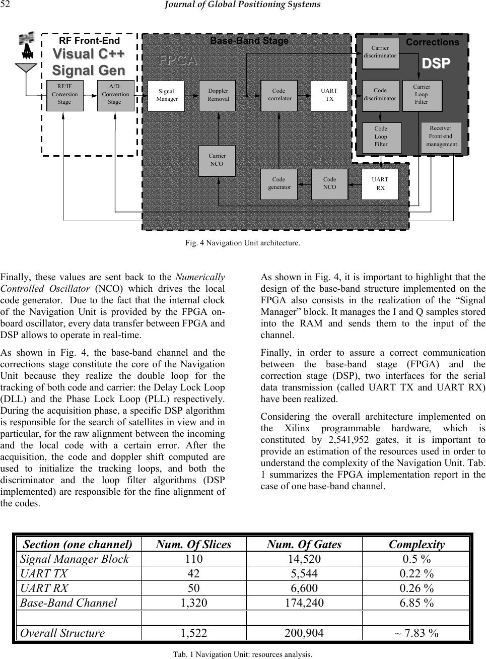 52 Journal of Global Positioning Systems Fig. 4 Navigation Unit architecture. Finally, these values are sent back to the Numerically Controlled Oscillator (NCO) which drives the local code generator. Due to the fact that the internal clock of the Navigation Unit is provided by the FPGA on- board oscillator, every data transfer between FPGA and DSP allows to operate in real-time. As shown in Fig. 4, the base-band channel and the corrections stage constitute the core of the Navigation Unit because they realize the double loop for the tracking of both code and carrier: the Delay Lock Loop (DLL) and the Phase Lock Loop (PLL) respectively. During the acquisition phase, a specific DSP algorithm is responsible for the search of satellites in view and in particular, for the raw alignment between the incoming and the local code with a certain error. After the acquisition, the code and doppler shift computed are used to initialize the tracking loops, and both the discriminator and the loop filter algorithms (DSP implemented) are responsible for the fine alignment of the codes. As shown in Fig. 4, it is important to highlight that the design of the base-band structure implemented on the FPGA also consists in the realization of the “Signal Manager” block. It manages the I and Q samples stored into the RAM and sends them to the input of the channel. Finally, in order to assure a correct communication between the base-band stage (FPGA) and the correction stage (DSP), two interfaces for the serial data transmission (called UART TX and UART RX) have been realized. Considering the overall architecture implemented on the Xilinx programmable hardware, which is constituted by 2,541,952 gates, it is important to provide an estimation of the resources used in order to understand the complexity of the Navigation Unit. Tab. 1 summarizes the FPGA implementation report in the case of one base-band channel. Section (one channel) Num. Of Slices Num. Of Gates Complexity Signal Manager Block 110 14,520 0.5 % UART TX 42 5,544 0.22 % UART RX 50 6,600 0.26 % Base-Band Channel 1,320 174,240 6.85 % Overall Structure 1,522 200,904 ~ 7.83 % Tab. 1 Navigation Unit: resources analysis. RF/IF Con version Stage A/D Convertion Stage Doppler Removal Code correlator Code discriminator Carrier discriminator Code Loop Filter Carrier Loop Filter Code NCO Code generator Carrier NCO Corrections Receiver Front-end management RF Front-End F FP PG GA A Base-Band Stage D DS SP P V Vi is su ua al l C C+ ++ + S Si i g gn na al l G Ge en n Signal Manager UART TX UART RX  Dovis et al.:Benefits of a Reconfigurable Software GNSS Receiver in Multipath Environment 53 3.2 Performance Results for the Navigation Unit In order to test the Navigation Unit performance the ability of acquiring a code and of maintaining the lock have been evaluated, The test of the SDR platform has been realized using the advanced Real Time Data eXchange (RTDX) controls which allow to create a buffer for the communication link between the DSP and a generic Host Application, which in this case is constituted by a Matlab routine. In presence of noise the sample stream has been obtained considering a value of C/N0 equal to 60 dBHz at the input of the RF filter. In particular, the double side band of the IF filter (see Fig. 4) has been set to 8 Mhz and a 3rd order Butterworth filter has been employed. 0200 4006008001000 12001400 1600 1800 2000 -500 0 500 1000 1500 2000 2500 Delay [half chip] Correlation Value Correlation Pattern (Acquisition) Fig. 5 Acquisition phase: correlation pattern. The sampling frequency used for the satellite signal generation within the simulator, has been set equal to 2.182 MHz and therefore, the system operates with 2.13 samples per chip. Incoming Code Local Replica Incoming Code Local Replica Fig. 6 Tracking phase: codes alignment. With a FPGA on-board clock of 65.472 MHz, samples at the input of the base-band channel are correlated with the local code over an integration time of one code period; it means that the maximum value for the output of the correlator can be 2,182. The actual value at the output of the correlator is acquired from the DSP, which compares it with the proper threshold in order to capture the peak in the Correlation Pattern (depicted in Fig. 4 in absence of noise). The DSP also shifts the local code replica (steps of ½ chip) in order to span all the possible delays. At the end of the acquisition phase, the delay between the two codes is used to track the signal. During this phase the correlation value increases because some DSP algorithms drive the local code generator in order to obtain the fine alignment (Fig. 6). In particular, an “Early-Late Envelope Normalized” discriminator (Equation 1) with a 2nd order FIR loop filter are implemented. 2222 2222 _ LLEE LLEE QIQI QIQI outputDiscr +++ +−+ = (1) 0 2.5 57.5 1012.5 15 17.5 20 22.5 25 -500 0 500 1000 1500 2000 2500 Time [s] Coorrelation Acquisition and Tracking Phases: the Correlation Fig. 7 Correlation during the acquisition and the tracking phases for signal without noise. In absence of noise the acquisition threshold is set equal to 1800. Fig. 7 and Fig. 8 depict the Navigation Unit performance results in terms of correlation values. Considering the tracking phase, it is possible to see that in presence of noise (Fig. 8) the correlation reaches a mean value of 600, while in the theoretical situation (Fig. 7) the mean of the correlation is near the maximum value of 2,182 according to the results obtained by simulation. It is then possible to conclude that this architecture allows for the realization of advanced modules for the implementation of complex algorithms based on satellite navigation signals.  54 Journal of Global Positioning Systems 0 2.5 57.51012.5 1517.52022.5 25 -400 -200 0 200 400 600 800 1000 Time [s] Correlation Acquisition and Tracking Phases: the Correlation Fig. 8 Correlation during the acquisition and the tracking phases for signal with noise. In this case the threshold used during the acquisition is decreased in order to detect the correlation peak. 4 Multipath Tracking Algorithm for Reducing the Code Alignment Error The reconfigurable structure described in the previous section has the goal to allow the implementation of advanced Internal Modules, as for example the multipath recovery algorithm. It is well know that multipath errors become particularly significant in urban or indoor navigation, where the presence of many scatterers around the receiver may be relevant. When a SIS replica, delayed within one chip with respect to Line Of Sight (LOS), arrives at the receiver the S-curve of the DLL is distorted. The punctual local code replica of the DLL can not be exactly aligned to the LOS and a systematic error in the pseudorange estimation is experienced. In the past several techniques to reduce the multipath error have been proposed. Among them it is possible to cite the narrow correlator (Braasch, 1996), which allows to get a better alignment reducing the spacing between the early and late local replicas. An innovative system for multipath recovery based on a multiple DLL architecture has been introduced in (Dovis et al., 2004), and its implementation in the SDR receiver is considered in this paper. It is important to highlight that the new architecture is quite different from common rejection techniques. In fact, it is based on the philosophy of the RAKE receiver for communications and employs specific DLLs to track the replicas in order to cancel the distortions of the S-curve of the tracking loop. The architecture implemented in the reconfigurable hardware is depicted in Fig. 9. A key role is played by the multipath Monitoring Unit which is in charge of activating the multistage architecture according to the scenario. In particular it has to: • estimate the number of replicas impinging at the antenna employing an algorithm, as for example (Laxton et al., 1977). • compare them with a predefined threshold to roughly determine their relevance to the distortion of the S-curve. • activate the multistage procedure for the tracking loop. ( ) tsd DLL 0 DLL 1 DLL NAV () tr + - ( ) tr 1 () tcP 0 ( ) tcP 1 ( ) trNAV ( ) tc NAV P 1 1 a 1 a IF Filter Multipath Monitoring Unit Multipath Tracking +- Down Sampling A/D Conversion Fig. 9 Multiple DLL architecture for one channel within the navigation receiver. For sake of presentation of the multistage procedure, let consider a generic user in an indoor scenario, where it is clear that the receiver performance are degraded by multipath due to the presence of obstacles around the antenna. In this scenario, the reconfigurable terminal is able to activate the Module for the Multipath recovery considering the n-th paths estimated as arriving at the antenna. In other words, the complexity of the algorithm is increased with respect to the number of multiple paths. Fig. 9 shows the innovative architecture in the case of one multipath arriving at the receiver, but it can be easily extendable to the general situation in which the input signal arrives at the antenna via n-th different paths. The local code replica of the DLL0 is usually delayed with respect to the LOS code due to the distortion of the S-curve. Such a code instance is subtracted from the filtered incoming code r(t), giving a signal r1(t) as input for the DLL1, which is therefore able to track the multipath. After a transient phase, the first DLL tracks the incoming LOS and the second multipath replica. The local code of DLL1, that follows the evolution of multipath, is then subtracted from the incoming code r(t) and the resulted signal is sent as input for the  Dovis et al.:Benefits of a Reconfigurable Software GNSS Receiver in Multipath Environment 55 DLLNAV. The local code of this last DLL can be used for pseudorange estimation. The innovative DLL architecture described aims at reducing the bias error in the code alignment. Therefore, the mean of the tracking error between the LOS code and the DLLNAV local code has been evaluated considering different values of C/N0 (which represents the ratio between the LOS power and the noise power spectral density at the input of the RF filter) and different multipath delays. 51 52 53 54 55 56 57 58 59 60 −0.01 0 0.01 0.02 0.03 0.04 0.05 0.06 0.07 0.08 0.09 C/No [dBHz] Mean of the tracking error [chip] Mean of the tracking error (200 samples) no multipath multipath simil−rake Fig. 10 - Comparison of the mean of the tracking jitter: common DLL with no multipath (dotted line), common DLL with multipath (τ1 = 0.7 chip) (dashed line), innovative multiple DLL (Fig. 9) with multipath (τ1 = 0.7 chip) (continuous line). Fig. 10 shows the result obtained by simulation of the module in case the multipath and LOS signals have the same phase rotation, the multipath is 0.7 chip delayed with respect to LOS and its amplitude is half the LOS amplitude. It can be noted that using a single DLL narrow correlator (0.125 chip spacing), no reasonable tracking is possible; in fact, the mean of the tracking jitter is about 0.07 chip apart from the correct zero crossing (dashed line in Fig. 10) for all the C/N0 values considered. Fig. 10 also reports the performance of a single DLL when no multipath is present (dotted line), and the performance of the innovative architecture (solid line). It can be observed from the picture that employing the new scheme, the systematic error can be significantly reduced for all C/N0 values. 0 0.5 1 1. 5 −0.01 0 0.01 0.02 0.03 0.04 0.05 0.06 0.07 0.08 Multipath Envelope − DLLs narrow correlator 0.125 spacing multipath delay with respect to LOS [chip] systematic error [chip] Fig. 11 - Theoretical and simulated multipath envelopes of a single narrow correlator (solid and dotted lines), theoretical and simulated multipath envelopes of the simil-RAKE architecture (dashed and dashed-dot lines). Fig. 11 shows the theoretical multipath envelops of a single DLL narrow correlator and of the whole simil- RAKE architecture compared to the systematic error obtained by simulation. Both simulation results and theoretical envelopes show that using the innovative architecture, it is possible to drastically reduce the systematic error for all the multipath delays considered. The distance between the simulated values and the theoretical curves can be explained considering that simulations have been performed in presence of noise and taking into account the Intermediate Frequency (IF) filter effect on the incoming signal. This structure can be simply extended and adapted to the external environment estimating the number of multipaths (thanks to the Multipath Monitoring Unit). Therefore, it is clear that it can play a key role in the realization of an advanced module for the on-fly reconfigurability procedure. The drawback of the proposed architecture resides in the increased computational complexity, and consequently to the power required to the FPGA/DSP architecture. It is important to point out that following the core idea behind the general statement of SDR, the implementation must be performed with particular attention to the mapping procedure onto the programmable platform, in order to assure the maximum degree of modularity. 5 Conclusions This paper has discussed the implementation of innovative functionalities for the realization of GNSS receiver according to the SDR philosophy. The study has been conducted highlighting novel aspects of the  56 Journal of Global Positioning Systems architecture which allows several degrees of reconfigurability. In particular, the design faced the choice of the best set of internal modules for satisfying the requirements in terms of precision, power consumption and time to fix. The implementation of the Navigation Unit has been analyzed in details because it represents the core for navigation modules. As a significant case-study of the reconfigurability opportunity, the adaptive multipath rejection algorithm has been discussed, presenting the simulation results of the implemented architecture. Acknowledgements Authors would like to thank ISMB (Istituto Superiore Mario Boella) research center for its support. In particular, all simulations and tests have been performed in the Navigation Lab within the Services and Applications Lab of ISMB. In addition, Massimiliano Spelat expresses many tanks indeed to ISMB for the financial support to his Ph.D. program. References Akos D M (2003) The role of Global Navigation Satellite Systems (GNSS) software radios in embedded systems, GPS solution, vol. 7, no. 1 Braasch M. W. (1996) Performance Comparison of Multipath Mitigating Receiver Architecture, IEEE PLANS 1996 Buracchini E (2000) The Software Radio Concept, Commun. Mag., vol.38, no.9, pp. 138-143 Dovis F, Gramazio A, Mulassano P (2002) SDR Technology Applied to Galileo Receivers, ION GPS 2002 Dovis F, Mulassano P, Pini M (2004) Multiple DLL Architecture for Multipath Recovery in Navigation Receivers, IEEE VTC 2004 Laxton M C, De Vilbiss S L (1977) GPS Multipath Mitigation During Code Tracking, in Proc. of the American Control Conference Mitola J (1995) The Software Radio Architecture, IEEE Commun. Mag., vol.33, no.5, pp. 26-38 Mulassano P, Dovis F, Avagnina D, Gramazio A (2001) REGAL: A Reconfigurable Receiver for GPS and Galileo, GNSS 2001 |