Paper Menu >>
Journal Menu >>
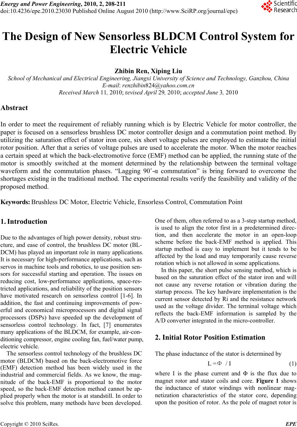 Energy and Power En gineering, 2010, 2, 208-211 doi:10.4236/epe.2010.23030 Published Online August 2010 (http://www.SciRP.org/journal/epe) Copyright © 2010 SciRes. EPE The Design of New Sensorless BLDCM Control System for Electric Vehicle Zhibin Ren, Xiping Liu School of Mechanical and Electrical Engineering, Jiangxi University of Science and Technology, Ganzhou, China E-mail: renzhibin824@yahoo.com.cn Received March 11, 2010; revised April 29, 2010; accepted June 3, 2010 Abstract In order to meet the requirement of reliably running which is by Electric Vehicle for motor controller, the paper is focused on a sensorless brushless DC motor controller design and a commutation point method. By utilizing the saturation effect of stator iron core, six short voltage pulses are employed to estimate the initial rotor position. After that a series of voltage pulses are used to accelerate the motor. When the motor reaches a certain speed at which the back-electromotive force (EMF) method can be applied, the running state of the motor is smoothly switched at the moment determined by the relationship between the terminal voltage waveform and the commutation phases. “Lagging 90˚-α commutation” is bring forward to overcome the shortages existing in the traditional method. The experimental results verify the feasibility and validity of the proposed method. Keywords: Brushless DC Motor, Electric Vehicle, Ensorless Control, Commutation Point 1. Introduction Due to the advantages of high power density, robust stru- cture, and ease of control, the brushless DC motor (BL- DCM) has played an important role in many applications. It is necessary for high-performance applications, such as servos in machine tools and robotics, to use position sen- sors for successful starting and operation. The issues on reducing cost, low-performance applications, space-res- tricted applications, and reliability of the position sensors have motivated research on sensorless control [1-6]. In addition, the fast and continuing improvements of pow- erful and economical microprocessors and digital signal processors (DSPs) have speeded up the development of sensorless control technology. In fact, [7] enumerates many applications of the BLDCM, for example, air-con- ditioning compressor, engine cooling fan, fuel/water pump, electric vehicle. The sensorless control technology of the brushless DC motor (BLDCM) based on the back-electromotive force (EMF) detection method has been widely used in the industrial and commercial fields. As we know, the mag- nitude of the back-EMF is proportional to the motor speed, so the back-EMF detection method cannot be ap- plied properly when the motor is at standstill. In order to solve this problem, many methods have been developed. One of them, often referred to as a 3-step startup method, is used to align the rotor first in a predetermined direc- tion, and then accelerate the motor in an open-loop scheme before the back-EMF method is applied. This startup method is easy to implement but it tends to be affected by the load and may temporarily cause reverse rotation which is not allowed in some applications. In this paper, the short pulse sensing method, which is based on the saturation effect of the stator iron and will not cause any reverse rotation or vibration during the startup process. The key hardware implementation is the current sensor detected by Ri and the resistance network used as the voltage divider. The terminal voltage which reflects the back-EMF information is sampled by the A/D converter integrated in the micro-controller. 2. Initial Rotor Position Estimation The phase inductance of the stator is determined by L =Φ / I (1) where I is the phase current and Φ is the flux due to magnet rotor and stator coils and core. Figure 1 shows the inductance of stator windings with nonlinear mag- netization characteristics of the stator core, depending upon the position of rotor. As the pole of magnet rotor is 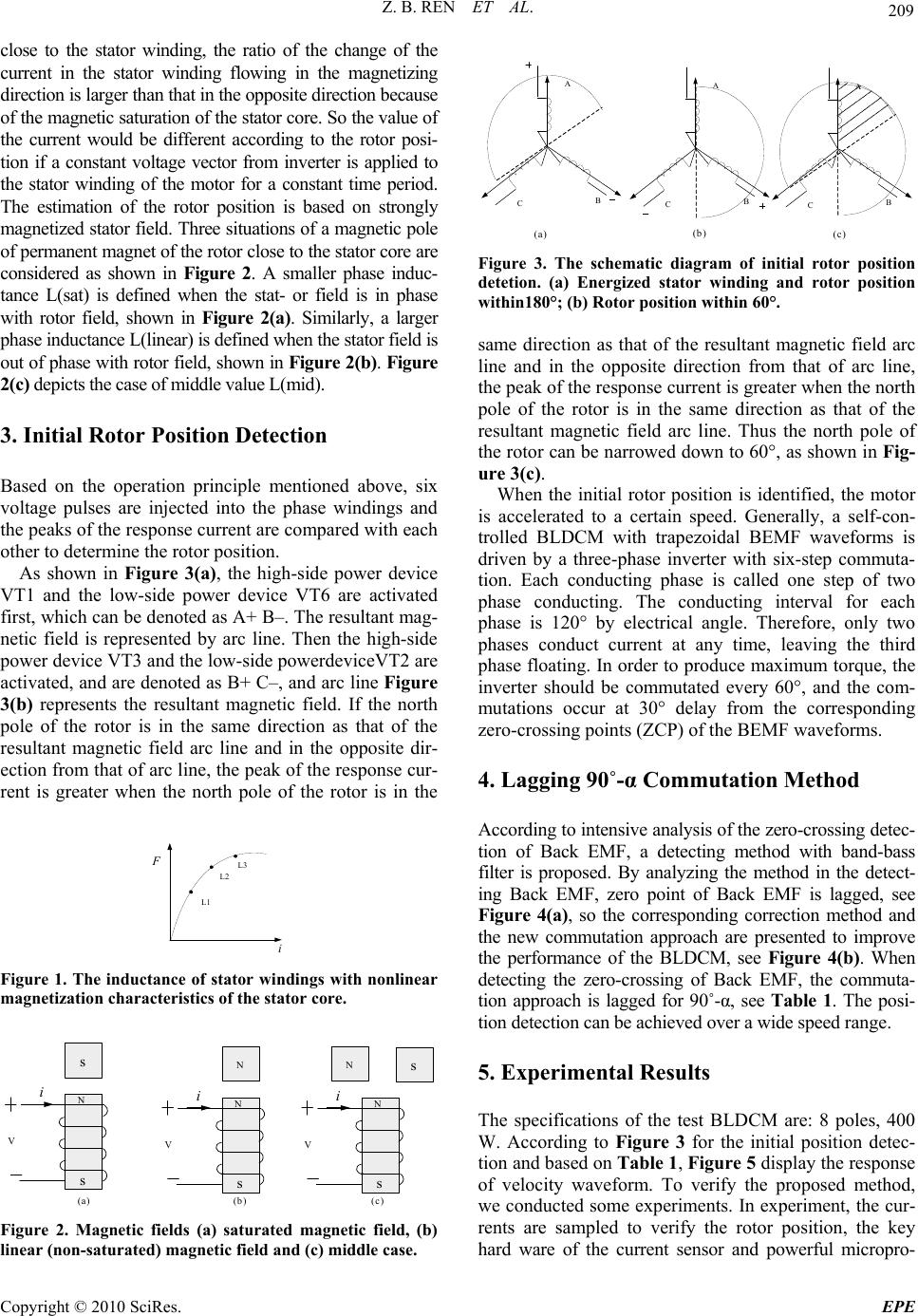 Z. B. REN ET AL. Copyright © 2010 SciRes. EPE 209 close to the stator winding, the ratio of the change of the current in the stator winding flowing in the magnetizing direction is larger than that in the opposite direction because of the magnetic saturation of the stator core. So the value of the current would be different according to the rotor posi- tion if a constant voltage vector from inverter is applied to the stator winding of the motor for a constant time period. The estimation of the rotor position is based on strongly magnetized stator field. Three situations of a magnetic pole of permanent magnet of the rotor close to the stator core are considered as shown in Figure 2. A smaller phase induc- tance L(sat) is defined when the stat- or field is in phase with rotor field, shown in Figure 2(a). Similarly, a larger phase inductance L(linear) is defined when the stator field is out of phase with rotor field, shown in Figure 2(b). Figure 2(c) depicts the case of middle value L(mid). 3. Initial Rotor Position Detection Based on the operation principle mentioned above, six voltage pulses are injected into the phase windings and the peaks of the response current are compared with each other to determine the rotor position. As shown in Figure 3(a), the high-side power device VT1 and the low-side power device VT6 are activated first, which can be denoted as A+ B–. The resultant mag- netic field is represented by arc line. Then the high-side power device VT3 and the low-side powerdeviceVT2 are activated, and are denoted as B+ C–, and arc line Figure 3(b) represents the resultant magnetic field. If the north pole of the rotor is in the same direction as that of the resultant magnetic field arc line and in the opposite dir- ection from that of arc line, the peak of the response cur- rent is greater when the north pole of the rotor is in the i F L1 L2 L3 Figure 1. The inductance of stator windings with nonlinear magnetization characteristics of the stator core. s V i s N N V i s N s V i s N N (a) (b) (c) Figure 2. Magnetic fields (a) saturated magnetic field, (b) linear (non-saturated) magnetic field and (c) middle case. A B C A B C A B C (a) (b) (c) Figure 3. The schematic diagram of initial rotor position detetion. (a) Energized stator winding and rotor position within180°; (b) Rotor position within 60°. same direction as that of the resultant magnetic field arc line and in the opposite direction from that of arc line, the peak of the response current is greater when the north pole of the rotor is in the same direction as that of the resultant magnetic field arc line. Thus the north pole of the rotor can be narrowed down to 60°, as shown in Fig- ure 3(c). When the initial rotor position is identified, the motor is accelerated to a certain speed. Generally, a self-con- trolled BLDCM with trapezoidal BEMF waveforms is driven by a three-phase inverter with six-step commuta- tion. Each conducting phase is called one step of two phase conducting. The conducting interval for each phase is 120° by electrical angle. Therefore, only two phases conduct current at any time, leaving the third phase floating. In order to produce maximum torque, the inverter should be commutated every 60°, and the com- mutations occur at 30° delay from the corresponding zero-crossing points (ZCP) of the BEMF waveforms. 4. Lagging 90˚-α Commutation Method According to intensive analysis of the zero-crossing detec- tion of Back EMF, a detecting method with band-bass filter is proposed. By analyzing the method in the detect- ing Back EMF, zero point of Back EMF is lagged, see Figure 4(a), so the corresponding correction method and the new commutation approach are presented to improve the performance of the BLDCM, see Figure 4(b). When detecting the zero-crossing of Back EMF, the commuta- tion approach is lagged for 90˚-α, see Table 1. The posi- tion detection can be achieved over a wide speed range. 5. Experimental Results The specifications of the test BLDCM are: 8 poles, 400 W. According to Figure 3 for the initial position detec- tion and based on Table 1, Figure 5 display the response of velocity waveform. To verify the proposed method, we conducted some experiments. In experiment, the cur- rents are sampled to verify the rotor position, the key hard ware of the current sensor and powerful micropro- 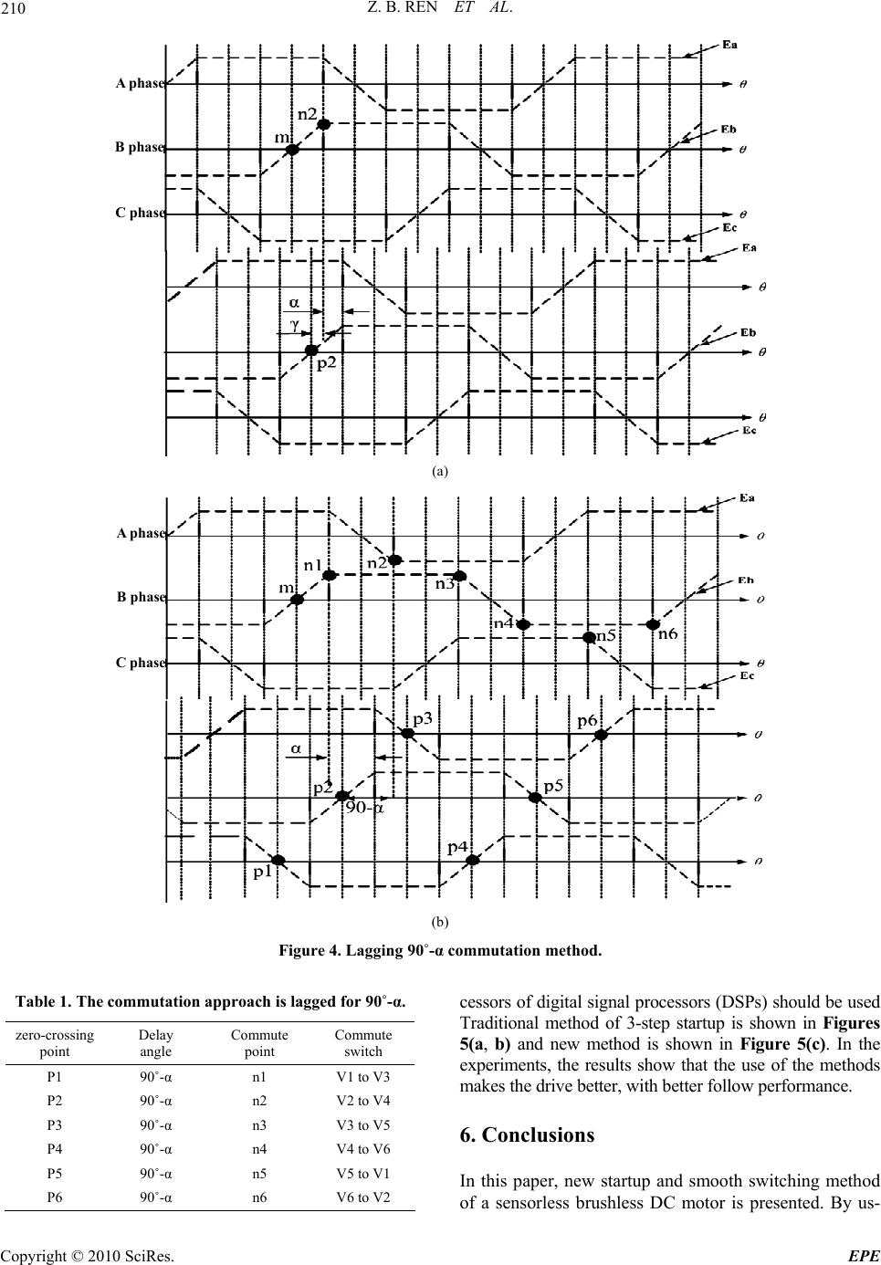 Z. B. REN ET AL. Copyright © 2010 SciRes. EPE 210 A phase B phase C phase (a) A phase B phase C phase (b) Figure 4. Lagging 90˚-α commutation method. Table 1. The commutation approach is lagged for 90˚-α. zero-crossing point Delay angle Commute point Commute switch P1 90˚-α n1 V1 to V3 P2 90˚-α n2 V2 to V4 P3 90˚-α n3 V3 to V5 P4 90˚-α n4 V4 to V6 P5 90˚-α n5 V5 to V1 P6 90˚-α n6 V6 to V2 cessors of digital signal processors (DSPs) should be used Traditional method of 3-step startup is shown in Figures 5(a, b) and new method is shown in Figure 5(c). In the experiments, the results show that the use of the methods makes the drive better, with better follow performance. 6. Conclusions In this paper, new startup and smooth switching method of a sensorless brushless DC motor is presented. By us- 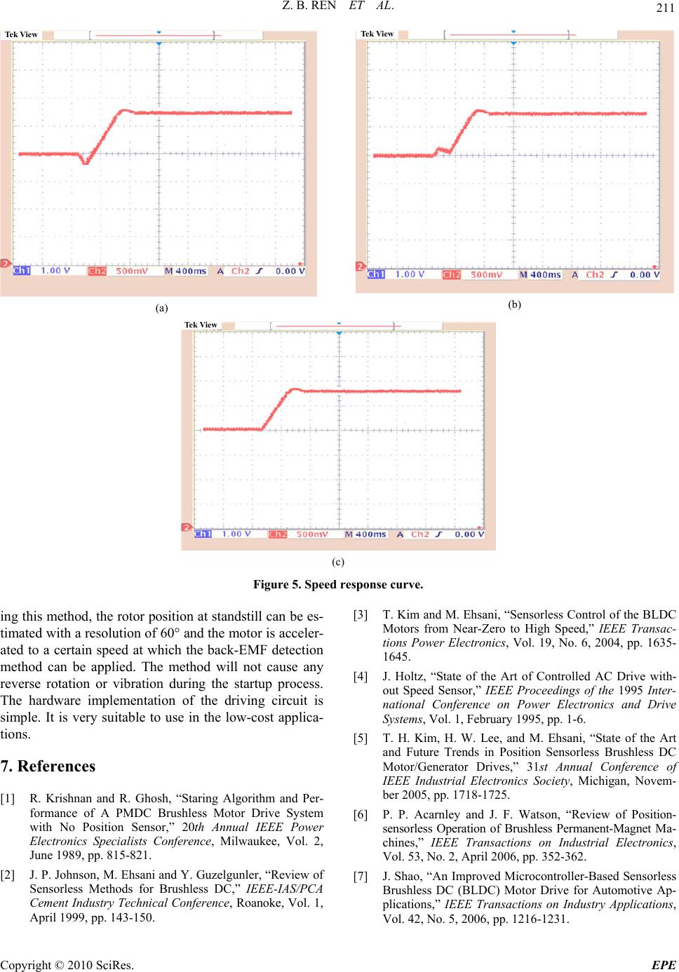 Z. B. REN ET AL. Copyright © 2010 SciRes. EPE 211 Tek View (a) Tek View (b) Tek View (c) Figure 5. Speed response curve. ing this method, the rotor position at standstill can be es- timated with a resolution of 60° and the motor is acceler- ated to a certain speed at which the back-EMF detection method can be applied. The method will not cause any reverse rotation or vibration during the startup process. The hardware implementation of the driving circuit is simple. It is very suitable to use in the low-cost applica- tions. 7. References [1] R. Krishnan and R. Ghosh, “Staring Algorithm and Per- formance of A PMDC Brushless Motor Drive System with No Position Sensor,” 20th Annual IEEE Power Electronics Specialists Conference, Milwaukee, Vol. 2, June 1989, pp. 815-821. [2] J. P. Johnson, M. Ehsani and Y. Guzelgunler, “Review of Sensorless Methods for Brushless DC,” IEEE-IAS/PCA Cement Industry Technical Conference, Roanoke, Vol. 1, April 1999, pp. 143-150. [3] T. Kim and M. Ehsani, “Sensorless Control of the BLDC Motors from Near-Zero to High Speed,” IEEE Transac- tions Power Electronics, Vol. 19, No. 6, 2004, pp. 1635- 1645. [4] J. Holtz, “State of the Art of Controlled AC Drive with- out Speed Sensor,” IEEE Proceedings of the 1995 Inter- national Conference on Power Electronics and Drive Systems, Vol. 1, February 1995, pp. 1-6. [5] T. H. Kim, H. W. Lee, and M. Ehsani, “State of the Art and Future Trends in Position Sensorless Brushless DC Motor/Generator Drives,” 31st Annual Conference of IEEE Industrial Electronics Society, Michigan, Novem- ber 2005, pp. 1718-1725. [6] P. P. Acarnley and J. F. Watson, “Review of Position- sensorless Operation of Brushless Permanent-Magnet Ma- chines,” IEEE Transactions on Industrial Electronics, Vol. 53, No. 2, April 2006, pp. 352-362. [7] J. Shao, “An Improved Microcontroller-Based Sensorless Brushless DC (BLDC) Motor Drive for Automotive Ap- plications,” IEEE Transactions on Industry Applications, Vol. 42, No. 5, 2006, pp. 1216-1231. |