Paper Menu >>
Journal Menu >>
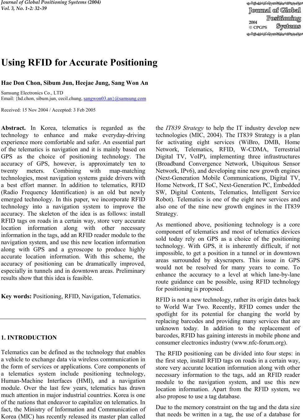 Journal of Global Positioning Systems (2004) Vol. 3, No. 1-2: 32-39 Using RFID for Accurate Positioning Hae Don Chon , Sibum Jun, Heej ae J ung, Sang Wo n A n Samsung Electronics Co. , LTD Email: {hd.chon, sibum.jun, cecil.chung, sangwon03.an}@samsung.com Received: 15 Nov 2004 / Accepted: 3 Feb 2005 Abstract. In Korea, telematics is regarded as the technology to enhance and make everyday-driving experience more comfortable and safer. An essential part of the telematics is navigation and it is mainly based on GPS as the choice of positioning technology. The accuracy of GPS, however, is approximately ten to twenty meters. Combining with map-matching technologies, most navigation systems guide drivers with a best effort manner. In addition to telematics, RFID (Radio Frequency Identification) is an old but newly emerged technology. In this paper, we incorporate RFID technology into a navigation system to improve the accuracy. The skeleton of the idea is as follows: install RFID tags on roads in a certain way, store very accurate location information along with other necessary information in the tags, add an RFID reader module to the navigation system, and use this new location information along with GPS and a gyroscope to produce highly accurate location information. With this scheme, the accuracy of positioning can be dramatically improved, especially in tunnels and in downtown areas. Preliminary results show that this idea is feasible. Key words: Positioning, RFID, Navigation, Telematics. 1. INTRODUCTI ON Telematics can be defined as the technology that enables a vehicle to exchange data via wireless communication in the form of services or applications. Core components of a telematics system include positioning technology, Human-Machine Interfaces (HMI), and a navigation module. Over the last few years, telematics has drawn much attention in major indu strial countries. Korea is one of the nations that end eavor to capitalize on telematics. In fact, the Ministry of Information and Communication of Korea (MIC) has recently released its master plan called the IT839 Strategy to help the IT industry develop new technologies (MIC, 2004). The IT839 Strategy is a plan for activating eight services (WiBro, DMB, Home Network, Telematics, RFID, W-CDMA, Terrestrial Digital TV, VoIP), implementing three infrastructures (Broadband Convergence Network, Ubiquitous Sensor Network, IPv6), and developing nine new growth engines (Next-Generation Mobile Communications, Digital TV, Home Network, IT SoC, Next-Generation PC, Embedded SW, Digital Contents, Telematics, Intelligent Service Robot). Telematics is one of the eight new services and also one of the nine new growth engines in the IT839 Strategy. As mentioned above, positioning technology is a core component of telematics and most of telematics devices sold today rely on GPS as a choice of the positioning technology. With GPS, it is inherently difficult, if not impossible, to get a position in a tunnel or in downtown areas surrounded by skyscrapers. This issue in GPS would not be resolved for many years to come. To enhance the accuracy to a level at which lane-by-lane route guidance can be possible, using RFID technology for positioning is proposed. RFID is not a new technology, rather its origin da tes back to World War Two. Recently, RFID comes under the spotlight for its potential for changing the world by replacing barcodes and providing many services that are unknown today. In addition to the replacement of barcodes, RFID has gaining interests in mobile phone and consumer electronics industry (www.nfc-forum.org). The RFID positioning can be divided into four steps: in the first step, install RFID tags on ro ads in a certain way, store very accurate location information along with other necessary information to the tags, add an RFID reader module to the navigation system, and use this new location information. Apart from the RFID system, we also propose to use a tag database. Due to the memory constraint on the tag and the data size that needs be written in a tag, the use of a database for 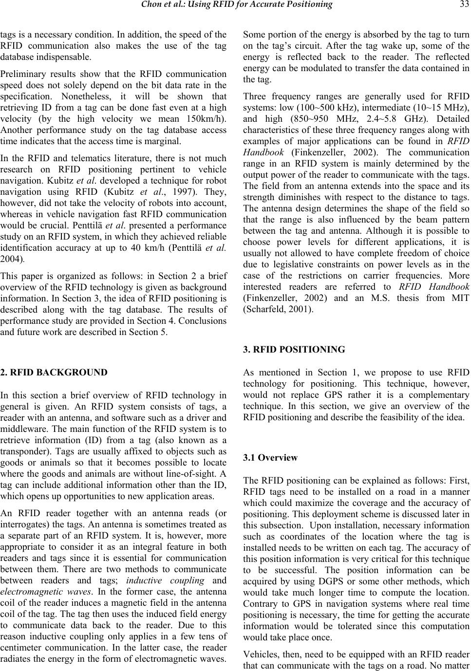 Chon et al.: Using RFID for Accurate Positioning 33 tags is a necessary condition . In addition , the speed of th e RFID communication also makes the use of the tag database indispensable. Preliminary results show that the RFID communication speed does not solely depend on the bit data rate in the specification. Nonetheless, it will be shown that retrieving ID from a tag can be done fast even at a high velocity (by the high velocity we mean 150km/h). Another performance study on the tag database access time indicates that the access time is marginal. In the RFID and telematics literature, there is not much research on RFID positioning pertinent to vehicle navigation. Kubitz et al. developed a technique for robot navigation using RFID (Kubitz et al., 1997). They, however, did not take the velocity of robots into account, whereas in vehicle navigation fast RFID communication would be crucial. Penttilä et al. presented a performance study on an RFID system, in which they achiev ed reliable identification accuracy at up to 40 km/h (Penttilä et al. 2004). This paper is organized as follows: in Section 2 a brief overview of the RFID technology is given as background information. In Section 3, the idea of RFID po sitioning is described along with the tag database. The results of performance study are provided in Section 4. Conclusions and future work are described in Section 5. 2. RFID BACKGROUND In this section a brief overview of RFID technology in general is given. An RFID system consists of tags, a reader with an antenna, and software such as a driver and middleware. The main function of the RFID system is to retrieve information (ID) from a tag (also known as a transponder). Tags are usually affixed to objects such as goods or animals so that it becomes possible to locate where the goods and animals are without line-of-sight. A tag can include additional information other than the ID, which opens up opportunities to new application areas. An RFID reader together with an antenna reads (or interrogates) the tags. An antenna is sometimes treated as a separate part of an RFID system. It is, however, more appropriate to consider it as an integral feature in both readers and tags since it is essential for communication between them. There are two methods to communicate between readers and tags; inductive coupling and electromagnetic waves. In the former case, the antenna coil of the reader induces a magnetic field in the antenna coil of the tag. The tag then uses the induced field energy to communicate data back to the reader. Due to this reason inductive coupling only applies in a few tens of centimeter communication. In the latter case, the reader radiates the energy in the form of electromagnetic waves. Some portion of th e energy is absorbed by the tag to tu rn on the tag’s circuit. After the tag wake up, some of the energy is reflected back to the reader. The reflected energy can be modulated to transfer the data contained in the tag. Three frequency ranges are generally used for RFID systems: low (100~500 kHz), intermediate (1 0~15 MHz), and high (850~950 MHz, 2.4~5.8 GHz). Detailed characteristics of these three frequency ranges along with examples of major applications can be found in RFID Handbook (Finkenzeller, 2002). The communication range in an RFID system is mainly determined by the output power of the reader to communicate with the tags. The field from an antenna extends into the space and its strength diminishes with respect to the distance to tags. The antenna design determines the shape of the field so that the range is also influenced by the beam pattern between the tag and antenna. Although it is possible to choose power levels for different applications, it is usually not allowed to have complete freedom of choice due to legislative constraints on power levels as in the case of the restrictions on carrier frequencies. More interested readers are referred to RFID Handbook (Finkenzeller, 2002) and an M.S. thesis from MIT (Scharfeld, 2001). 3. RFID POSITIONING As mentioned in Section 1, we propose to use RFID technology for positioning. This technique, however, would not replace GPS rather it is a complementary technique. In this section, we give an overview of the RFID positioning and describe the feasibility of the idea. 3.1 Overview The RFID positioning can be explained as follows: First, RFID tags need to be installed on a road in a manner which could maximize the coverage and the accuracy of positioning. This dep loyment scheme is discussed later in this subsection. Upon installatio n, necessary information such as coordinates of the location where the tag is installed needs to be written on each tag. The accuracy of this position information is v ery critical for this technique to be successful. The position information can be acquired by using DGPS or some other methods, which would take much longer time to compute the location. Contrary to GPS in navigation systems where real time positioning is necessary, the time for getting the accurate information would be tolerated since this computation would take place once. Vehicles, then, need to be equipped with an RFID reader that can communicate with the tags on a road. No matter 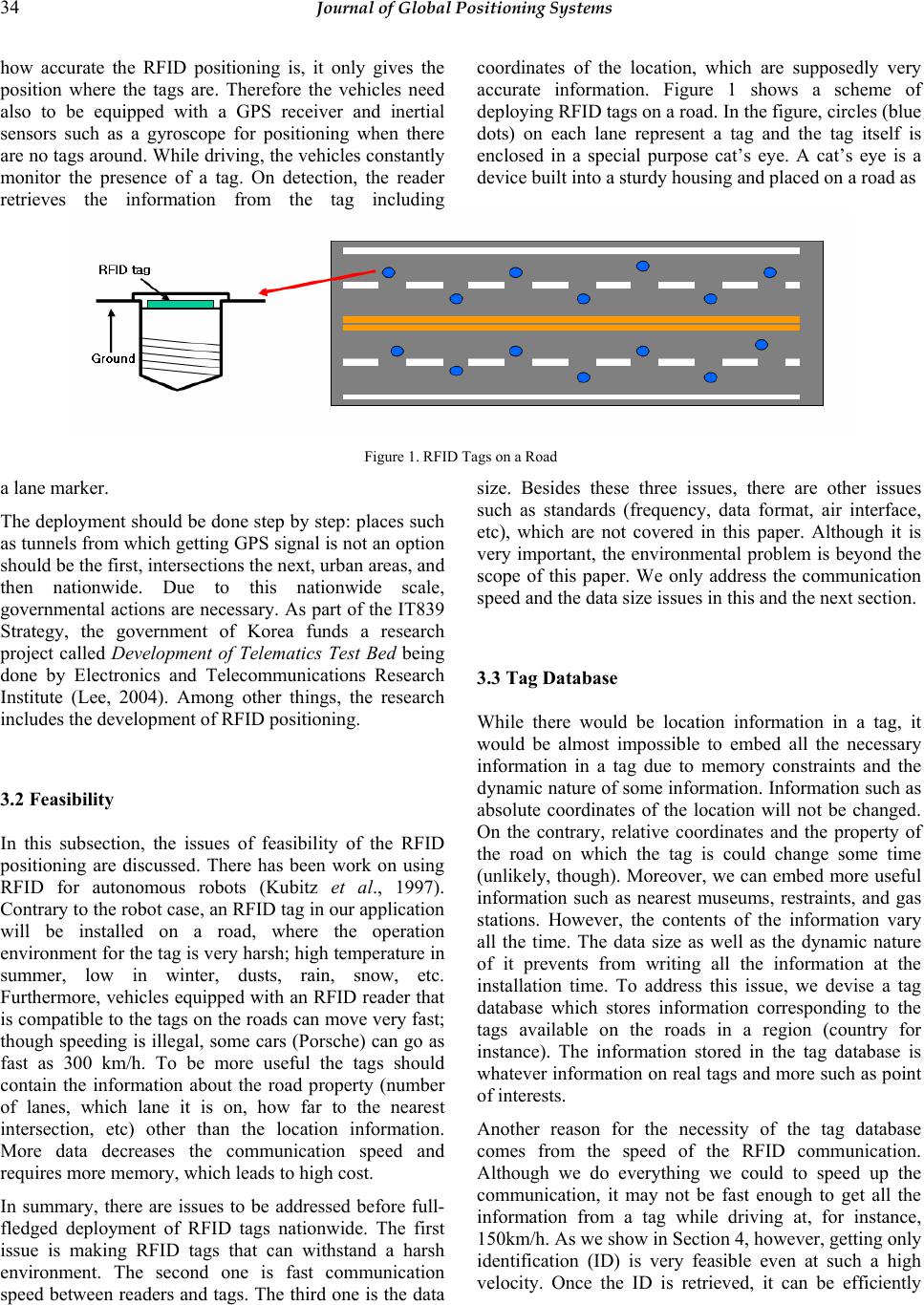 34 Journal of Global Positioning Systems how accurate the RFID positioning is, it only gives the position where the tags are. Therefore the vehicles need also to be equipped with a GPS receiver and inertial sensors such as a gyroscope for positioning when there are no tags around. While driving, the vehicles constantly monitor the presence of a tag. On detection, the reader retrieves the information from the tag including coordinates of the location, which are supposedly very accurate information. Figure 1 shows a scheme of deploying RFID tags on a road. In the figure, circles (blue dots) on each lane represent a tag and the tag itself is enclosed in a special purpose cat’s eye. A cat’s eye is a device built into a sturdy housing and placed on a road as Figure 1. RFID Tags on a Road a lane marker. The deployment should be done step by step: places such as tunnels from which getting GPS signal is not an option should be the first, intersections the next, urban areas, and then nationwide. Due to this nationwide scale, governmental actions are necessary. As part of the IT839 Strategy, the government of Korea funds a research project called Development of Telematics Test Bed being done by Electronics and Telecommunications Research Institute (Lee, 2004). Among other things, the research includes the development of RFID positioning. 3.2 Feasibility In this subsection, the issues of feasibility of the RFID positioning are discussed. There has been work on using RFID for autonomous robots (Kubitz et al., 1997). Contrary to the robo t case, an RFID tag in our application will be installed on a road, where the operation environment for the tag is very harsh; high temperature in summer, low in winter, dusts, rain, snow, etc. Furthermore, vehicles equipped with an RFID re ader that is compatible to the tags on the roads can move very fast; though speeding is illega l, some cars (Porsche) can go as fast as 300 km/h. To be more useful the tags should contain the information about the road property (number of lanes, which lane it is on, how far to the nearest intersection, etc) other than the location information. More data decreases the communication speed and requires more memory, which leads to high cost. In summary, there are issues to be addressed before full- fledged deployment of RFID tags nationwide. The first issue is making RFID tags that can withstand a harsh environment. The second one is fast communication speed between readers and tags. The third one is the data size. Besides these three issues, there are other issues such as standards (frequency, data format, air interface, etc), which are not covered in this paper. Although it is very important, the environmental problem is beyond the scope of this paper. We only address the communication speed and the data size issues in this and the next section. 3.3 Tag Database While there would be location information in a tag, it would be almost impossible to embed all the necessary information in a tag due to memory constraints and the dynamic nature of some information. Information such as absolute coordinates of the location will not be changed. On the contrary, relative coordinates and the property of the road on which the tag is could change some time (unlikely, though). Moreover, we can embed more useful information such as nearest museums, restraints, and gas stations. However, the contents of the information vary all the time. The data size as well as the dynamic nature of it prevents from writing all the information at the installation time. To address this issue, we devise a tag database which stores information corresponding to the tags available on the roads in a region (country for instance). The information stored in the tag database is whatever information on real tags and more such as point of interests. Another reason for the necessity of the tag database comes from the speed of the RFID communication. Although we do everything we could to speed up the communication, it may not be fast enough to get all the information from a tag while driving at, for instance, 150km/h. As we show in Section 4, however, getting only identification (ID) is very feasible even at such a high velocity. Once the ID is retrieved, it can be efficiently 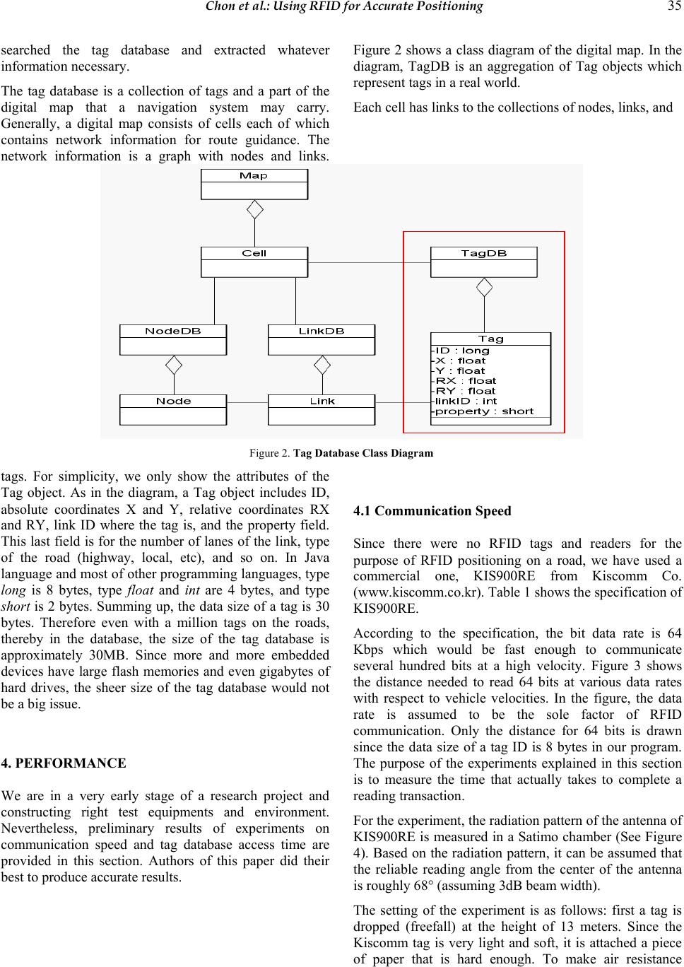 Chon et al.: Using RFID for Accurate Positioning 35 searched the tag database and extracted whatever information necessary. The tag database is a collection of tags and a part of the digital map that a navigation system may carry. Generally, a digital map consists of cells each of which contains network information for route guidance. The network information is a graph with nodes and links. Figure 2 shows a class diagram of the digital map. In the diagram, TagDB is an aggregation of Tag objects which represent tags in a real world. Each cell has links to the collections of nodes, links, and Figure 2. Tag Database Class Dia gr am tags. For simplicity, we only show the attributes of the Tag object. As in the diagram, a Tag object includes ID, absolute coordinates X and Y, relative coordinates RX and RY, link ID where the tag is, and the property field. This last field is for the number of lanes of the link, type of the road (highway, local, etc), and so on. In Java language and most of other programming languages, type long is 8 bytes, type float and int are 4 bytes, and type short is 2 bytes. Summing up, the data size of a tag is 30 bytes. Therefore even with a million tags on the roads, thereby in the database, the size of the tag database is approximately 30MB. Since more and more embedded devices have large flash memories and even gigabytes of hard drives, the sheer size of the tag database would not be a big issue. 4. PERFORMANCE We are in a very early stage of a research project and constructing right test equipments and environment. Nevertheless, preliminary results of experiments on communication speed and tag database access time are provided in this section. Authors of this paper did their best to produce accurate results. 4.1 Communication Spe ed Since there were no RFID tags and readers for the purpose of RFID positioning on a road, we have used a commercial one, KIS900RE from Kiscomm Co. (www.kiscomm.co.kr). Table 1 shows the specification of KIS900RE. According to the specification, the bit data rate is 64 Kbps which would be fast enough to communicate several hundred bits at a high velocity. Figure 3 shows the distance needed to read 64 bits at various data rates with respect to vehicle velocities. In the figure, the data rate is assumed to be the sole factor of RFID communication. Only the distance for 64 bits is drawn since the data size of a tag ID is 8 bytes in our program. The purpose of the experiments explained in this section is to measure the time that actually takes to complete a reading transaction. For the experiment, the radiation pattern of the antenna of KIS900RE is measured in a Satimo chamber (See Figure 4). Based on the radiation pattern, it can be assumed that the reliable reading angle from the center of the antenna is roughly 68 ° (assuming 3dB beam width). The setting of the experiment is as follows: first a tag is dropped (freefall) at the height of 13 meters. Since the Kiscomm tag is very light and soft, it is attached a piece of paper that is hard enough. To make air resistance 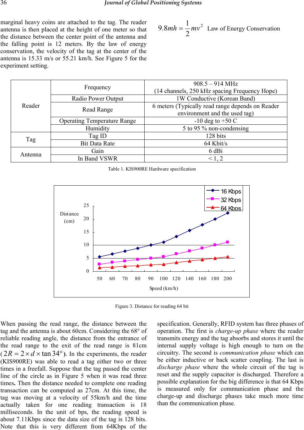 36 Journal of Global Positioning Systems marginal heavy coins are attached to the tag. The reader antenna is then placed at the height of one meter so that the distance between the center point of the antenna and the falling point is 12 meters. By the law of energy conservation, the velocity of the tag at the center of the antenna is 15.33 m/s or 55.21 km/h. See Figure 5 for the experiment setting. 2 2 1 8.9 mvmh = Law of Energy Conservation Frequency 908.5 – 914 MHz (14 channels, 250 kHz spacing Frequency Hope) Radio Power Output 1W Conductive (Korean Band) Read Range 6 meters (Typically read range depends on Reader environment and the used tag) Operating Temperature Range -10 deg to +50 C Reader Humidity 5 to 95 % non-condensing Tag ID 128 bits Tag Bit Data Rate 64 Kbit/s Gain 6 dBi Antenna In Band VSWR < 1, 2 Table 1. KIS900RE Hardware specification 0 5 10 15 20 25 5060708090100 120140 160 180 200 Speed (km/h) Distance (cm) 16 Kbps 32 Kbps 64 Kbps Figure 3. Distance for reading 64 bit When passing the read range, the distance between the tag and the antenna is about 60cm. Considering the 68° of reliable reading angle, the distance from the entrance of the read range to the exit of the read range is 81cm (°××= 34tan22 dR ). In the experiments, the reader (KIS900RE) was able to read a tag either two or three times in a freefall. Suppose that the tag passed the center line of the circle as in Figure 5 when it was read three times. Then the distance needed to complete one reading transaction can be computed as 27cm. At this time, the tag was moving at a velocity of 55km/h and the time actually taken for one reading transaction is 18 milliseconds. In the unit of bps, the reading speed is about 7.11Kbps since the data size of the tag is 128 bits. Note that this is very different from 64Kbps of the specification. Generally, RFID system has three phases of operation. The first is charge-up phase where the reader transmits energy and the tag absorbs and stores it until the internal supply voltage is high enough to turn on the circuitry. The second is communication phase which can be either inductive or back scatter coupling. The last is discharge phase where the whole circuit of the tag is reset and the supply capacitor is discharged. Therefore a possible explanation for the big difference is that 64 Kbps is measured only for communication phase and the charge-up and discharge phases take much more time than the communication phase. 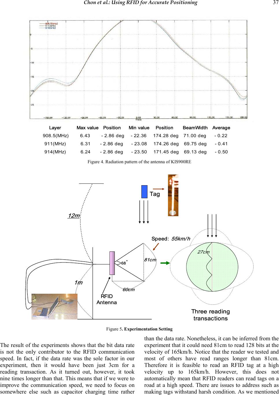 Chon et al.: Using RFID for Accurate Positioning 37 Layer Max value Position Min value Position BeamWidth Average 908.5(MHz) 6.43 -2.86 deg -22.36 174.28 deg 71.00 deg - 0.22 911(MHz) 6.31 -2.86 deg -23.08 174.26 deg 69.75 deg -0.41 914(MHz) 6.24 -2.86 deg -23.50 171.45 deg 69.13 deg -0.50 Figure 4. Radiation pattern of the antenna of KIS900RE Speed: 55km/h 81cm 1m 60cm RFID Antenna 27cm Three reading transactions Tag 12m 68 ˚ Speed: 55km/h 81cm 1m 60cm RFID Antenna 27cm Three reading transactions Tag 12m 68 ˚ Figure 5. Experimentation Setting The result of the experiments shows that the bit data rate is not the only contributor to the RFID communication speed. In fact, if the data rate was the sole factor in our experiment, then it would have been just 3cm for a reading transaction. As it turned out, however, it took nine times longer than that. This means that if we were to improve the communication speed, we need to focus on somewhere else such as capacitor charging time rather than the data rate. Nonetheless, it can be inferred from the experiment that it could need 81cm to read 128 bits at the velocity of 165k m/h. Notice that the read er we tested and most of others have read ranges longer than 81cm. Therefore it is feasible to read an RFID tag at a high velocity up to 165km/h. However, this does not automatically mean that RFID readers can read tags on a road at a high speed. There are issues to address such as making tags withstand harsh conditio n. As we mentioned 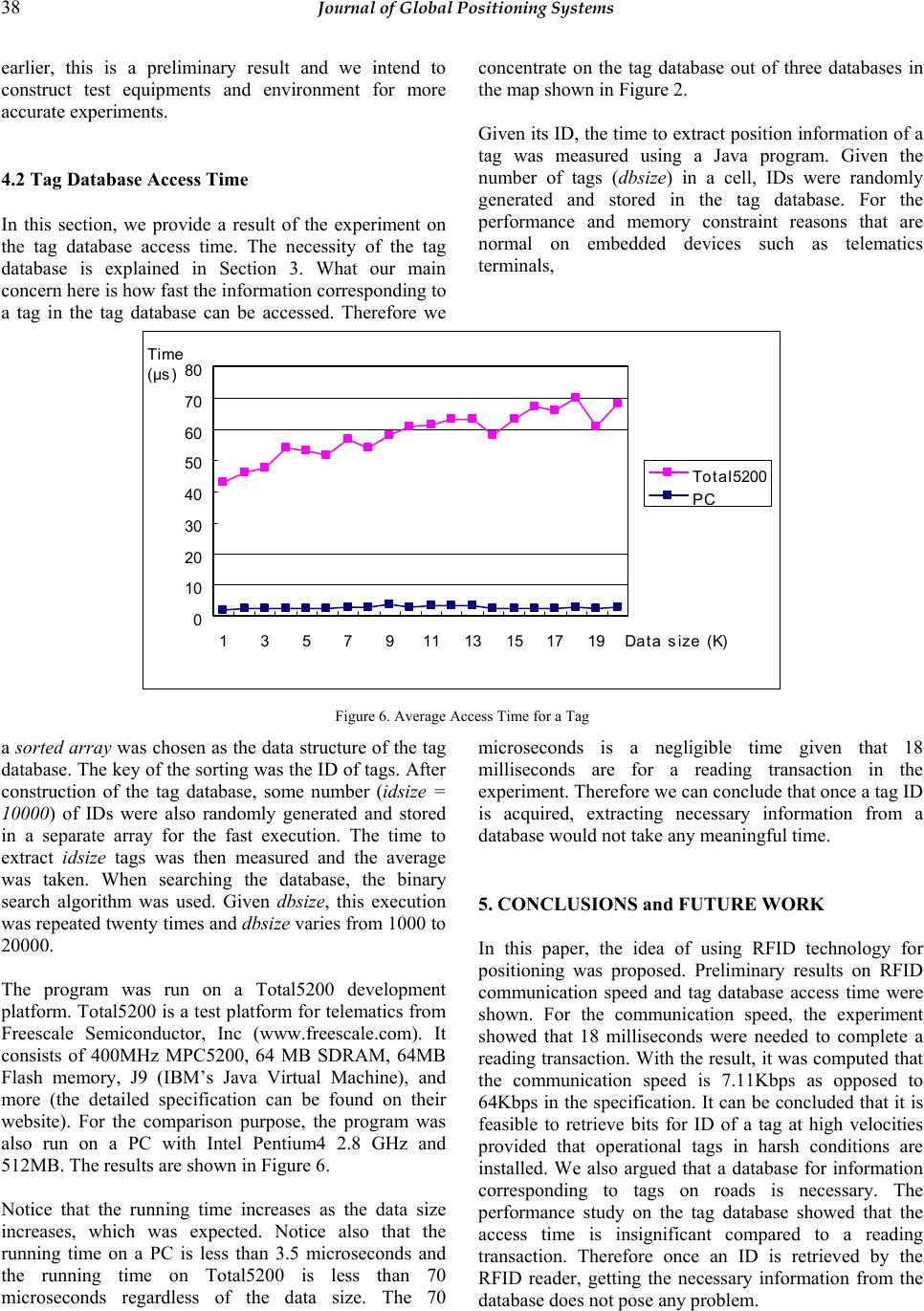 38 Journal of Global Positioning Systems earlier, this is a preliminary result and we intend to construct test equipments and environment for more accurate experiments. 4.2 Tag Database Access Time In this section, we provide a result of the experiment on the tag database access time. The necessity of the tag database is explained in Section 3. What our main concern here is how fast the information corresponding to a tag in the tag database can be accessed. Therefore we concentrate on the tag database out of three databases in the map shown in Figure 2. Given its ID, the time to extract position information of a tag was measured using a Java program. Given the number of tags (dbsize) in a cell, IDs were randomly generated and stored in the tag database. For the performance and memory constraint reasons that are normal on embedded devices such as telematics terminals, 0 10 20 30 40 50 60 70 80 135791113151719Data size ( K ) Total5200 PC Time (μs) Figure 6. Average Access Time for a Tag a sorted array was chosen as the data structure of the tag database. The key of th e sorting was the ID of tags. After construction of the tag database, some number (idsize = 10000) of IDs were also randomly generated and stored in a separate array for the fast execution. The time to extract idsize tags was then measured and the average was taken. When searching the database, the binary search algorithm was used. Given dbsize, this execution was repeated twenty times and dbsize varies from 1000 to 20000. The program was run on a Total5200 development platform. Total5200 is a test platform for telematics from Freescale Semiconductor, Inc (www.freescale.com). It consists of 400MHz MPC5200, 64 MB SDRAM, 64MB Flash memory, J9 (IBM’s Java Virtual Machine), and more (the detailed specification can be found on their website). For the comparison purpose, the program was also run on a PC with Intel Pentium4 2.8 GHz and 512MB. The results are shown in Figure 6. Notice that the running time increases as the data size increases, which was expected. Notice also that the running time on a PC is less than 3.5 microseconds and the running time on Total5200 is less than 70 microseconds regardless of the data size. The 70 microseconds is a negligible time given that 18 milliseconds are for a reading transaction in the experiment. Therefore we can conclude that once a tag ID is acquired, extracting necessary information from a database would not take any meaningful time. 5. CONCLUSIONS and FU T UR E WORK In this paper, the idea of using RFID technology for positioning was proposed. Preliminary results on RFID communication speed and tag database access time were shown. For the communication speed, the experiment showed that 18 milliseconds were needed to complete a reading transaction. W ith the result, it was computed that the communication speed is 7.11Kbps as opposed to 64Kbps in the specification. It can be concluded that it is feasible to retrieve bits for ID of a tag at high velocities provided that operational tags in harsh conditions are installed. We also argued that a database for information corresponding to tags on roads is necessary. The performance study on the tag database showed that the access time is insignificant compared to a reading transaction. Therefore once an ID is retrieved by the RFID reader, getting the necessary information from the database does no t pose any probl em.  Chon et al.: Using RFID for Accurate Positioning 39 Although it is our conclusion that the idea of RFID positioning is feasible, there are many issues to resolve before any full-fledged deployment. Some of the issues are (1) making a tag to withstand harsh conditions, (2) testing communication speed at up to 150 km/h, (3) developing a scheme to combine an RFID reader, a GPS receiver, and a gyroscope to produce a consistent and accurate position information, and (4) developing a tag database management algorithm and program for future use. As future work, these issues will be investigated. ACKNOWLEDGEMENTS: We give our thanks to Yunkyoung Ko for his cooperation in measuring the radiation pattern of the RFID antenna. REFERENCES Finkenzeller K, RFID Handbook: Fundamentals and Applcations in Contactless Smart cards and Identification (2002) Kiscomm co., LTD, KIS900RE View, www .kiscomm.co.kr Kubitz O, Berger M, Perlick M and Dumoulin R (1997) Application of Radio Frequency Identification Devices to Support Navigation of Autonomous Mobile Robots, IEEE 47th Vehicular Technology Conference, 126-130 Lee J (2004) Development of Telematics Test Bed, TTA Telematics Standards & Technology Seminar (www.tta.or.kr, in Korean) Ministry of Information and Communication (2004) IT 839 Strategy Master Plan, www.mic.go.kr Penttilä K, Sydänheimo L, and Kivikoski M (2004) Performance development of a high-speed automatic object identification using passive RFID technology, Proceedings of the 2004 IEEE International Conference on Robotics & Automation, 4864-4868 Scharfeld T (2001) An Analysis of the Fundamental Constraints on Low Cost Passive Radio Frequency Identification System Design, MIT M.S. Thesis Siegemund F and Flörkemeier C (2003) Interaction in Pervasive Computing Settings using Bluetooth-Enabled Active Tags and Passive RFID Technology together with Mobile Phones, Proceedings of the First IEEE International Conference on Pervasive Computing and Communications, 378-387 |