 Advances in Chemical Engineering and Science, 2012, 2, 508-513 http://dx.doi.org/10.4236/aces.2012.24062 Published Online October 2012 (http://www.SciRP.org/journal/aces) Separation and Recovery of Iodine from Aqueous Solution by Permeation and Chemical Desorption (PCD) Using a Silicone Rubber Membrane Jun Sawai1*, Hitomi Tomizuka1, Naoki Hatanaka1, Tamotsu Minami1, Mikio Kikuchi1, Toshimitsu Ishii2 1Faculty of Applied Bioscience, Kanagawa Institute of Technology, Atsugi, Japan 2Godo Shigen Sangyo Co., Ltd. Nanaido, Chiba, Japan Email: *sawai@bio.kanagawa-it.ac.jp Received September 5, 2012; revised October 4, 2012; accepted October 12, 2012 ABSTRACT New technologies for iodine separation and recovery are required to decrease environmental pollution and improve io- dine production. Separation and recovery of iodine (I2) in aqueous solution was achieved using permeation and chemi- cal desorption (PCD) with a silicone rubber membrane (SRM). The SRM separated an aqueous feed solution from an alkaline or reducing recovery solution such as a mixture of sodium hydrate and sodium sulfate. The I2 crossed the membrane from the aqueous feed so lution into the recov ery solution, where it was converted into iodide (I–). Iodide in the recovery solution did not return to the feed solution across the SRM. An acidic feed solution promoted a high re- covery of iodine. The permeation process followed first-order kinetics, allowing the overall mass-transfer coefficient and parameters related to permeation of I2 through the SRM to be determined. Permeability of I2 increased with tem- perature, and the apparent activation energy (Ea) for penetration of I2 through the SRM was determined. The value of Ea for I2 was of the same order of magnitude as those for phenols and anilines. The large membrane/aqueous distribution coefficient for I2 indicated that I2 had a high affinity toward the SRM. These results indicate that the PCD method is effective and powerful for separation and recovery of iodine from aqueous solutions. Keywords: Membrane Separation; Permeation and Chemical Desorption (PCD) Method; Diffusion Coefficient; Membrane/Aqueous Distribution Coefficient; Polydimethylsiloxane 1. Introduction Iodine is used in many applications, such as X-ray con- trast media [1] and disinfectants [2], because of its high reactivity. Potassium iodide, which is essential to growth, is often added to table salt and feed to prevent iodine deficiency. Iodine and iodine compounds are also used as photo-sensitizers, catalysts, stabilizers, polarizing films on liquid crystal displays, and reaction intermediates [3]. Iodine in brine is usually produced through a blow- ing-out process [3-5]. The iodine concentration in brine is 60 - 350 mg·L –1 (0.2 - 1.3 mM) [6], but the recovery of iodine from brine requires large-scale equipment. The development of new small-scale, energy-saving proc- esses for iodine separation and recovery need to be de- veloped to decrease environmental pollution and improve iodine production. The membrane separation process is widely used in industry because it offers several advantages, such as low energy consumption, low space use, and simple process design, compared to other processes [7,8]. The permea- tion and chemical desorption (PCD) method has been proposed as an alternative method for iodine recovery [9,10]. A target substance can be separated and recovered from an aqueous solution by altering the characteristics of the substance from high affinity toward the membrane to poor affinity by a chemical reaction, such as neutrali- zation or oxidation-reduction. A previous study [11] ex- plored the separation and recovery of 4-substituted phe- nol and aniline derivatives from aqueous solutions using PCD with a silicone rubber membrane (SRM). Phenols or anilines in aqueous solution were recovered success- fully into aqueous NaOH or HCl solutions, respectively. A comparison between PCD and pervaporation (PV) was performed, which revealed that the removal rate of phe- nols from aqueous solution by PCD was significantly greater than by PV, and showed that PCD is effective for separation and recovery of low-volatility compounds [12,13]. Ferreira et al. proposed a recovery system for *Corresponding a uthor. C opyright © 2012 SciRes. ACES  J. SAWAI ET AL. 509 phenols and anilines using an SRM as a membrane aro- matic recovery system (MARS) and reported success of a pilot-scale plant [14,15]. Iodine is attracted to the hydrophobic silicone mem- brane because of its high solubility in organic solvents, offering the ability to separate it by PCD. Thus, a project was undertaken to recover iodine and its derivatives that had been released into the environment and to improve iodine production by PCD using an SRM [9,10]. In this study, we tried to apply the PCD method for separation of iodine from water and obtained the recovery condi- tions and parameters for permeation of I2 to the SRM. We have showed that the PCD method was effective and powerful for separation and recovery of iodine from aqueous solutions and the possib ility of the PCD method to simplify the production of iodine and reduce energy consumption and space needs in this paper. 2. Materials and Methods 2.1. Permeation Experiment The apparatus used for PCD was the same as described previously [11]. The SRM (As One Co., Ltd., Osaka, Japan) was inserted between two glass cells (capacity: 250 mL) and was fixed by flanges. The thickness of the SRM varied from 0.05 to 0.3 mm, with an effective area of 1.5 × 10⁻³ m2. The SRM was made of polydimethylsi- loxane and fumed silica, which was confirmed using at- tenuated total reflectance Fourier-transform infrared spectroscopy (data not shown). An iodine (Kanto Kagaku Co., Ltd., Tokyo, Japan) solution was prepared at a con- centration of 0.8 mmol-I2 L–1 in distilled water. The pH of the iodine solution was adjusted using HCl and NaOH solutions. The iodine solution (250 mL) was added into the feed side cell. The composition of the solutions (250 mL) assayed on the recovery side is shown in Table 1. The two solutions were agitated using a magnetic stirrer. Samples (1 mL) were withdrawn from both cells at regu- lar intervals, and the iodine and iodide concentrations on each side solution were determined as described below. The experimental temperature (15˚C - 45˚C) was con- trolled using a water bath. 2.2. Determination of Iodine or Iodide Concentration High performance liquid chromatography (HPLC) using a UV detector measured the concentration of iodine. Volumes of 0.1 mL sodium sulfite solution (0.5 mol·L–1) and 0.5 mL of acetic acid buffer solution (0.2 mol·L–1) were added to 1 mL of the sample solution. This mixture was analyzed to determine iodide concentration under the conditions shown in Table 2. All reagents were analytic- cal grade purchased from Kanto Kagaku Co., Ltd. (To- kyo, Japan). 2.3. Measurement of Membrane Distribution Coefficient of I2 An SRM (20 × 20 mm) with a thickness of 0.05 mm was immersed for 24 h in a bottle containing 10 mL of fresh iodine solution at 0.80 or 1.6 mmol-I2 L–1 at pH4.0, and the equilibrium iodine concentration (CE1) was deter- mined by using the HPLC as described above. The SRM was removed from the solution, drained, and immersed in 20 mmol·L–1 NaOH. After 24 h, the concentration of iodide released from the SRM in the NaOH so lution (CE2) was determined. The membrane distribution coefficient, mc, was estimated based on the values of CE1 and CE2. The equilibrium experiments were performed at 25˚C. Each experiment was conducted 3 times and average value was shown as a resu lt; the SE of the average value remained below 15%. 3. Results and Discussion 3.1. pH Dependency of Iodine Permeation through SRM The permeation of iodine through SRM was investigated using NaOH solution in the recovery at different pH val- ues of the iodine solu tion in the feed cell. Figure 1 show s the permeation ratio, Rp, at different feed cell pH values after 5 h. The SRM thickness was 0.05 mm, and tem- perature was 25˚C. RP was ob t a i ned using Equation (1): Table 1. Overall mass transfer coefficients (KOL) of iodine for several recovery solutions. Concentration (mmol·l–1) Reagents Na2CO3 Na2SO3 KOL × 105 (m·s–1) Na2CO3 + Na2SO4*1 1 0.95 10 10 1.2 50 50 1.3 100 100 1.2 *Na2CO3 and Na 2SO3 are equimolar. Table 2. HPLC measurement conditions. Model LC-6A (Shimadzu Co, Kyoto, Japan) Detector UV spectrophotometric detector SPD-6A (Shimidzu Co.) 220 nm Column Luna 5 m C18, 150 mm × 4.6 mm (Phenomenex, CA, USA) Column temperature 40˚C Mobile phase CH3CN/H2O-20 mmol·l–1 tetrabutylammonium phosphate = 25 /75 (Kanto Kagaku Co., L TD., Tokyo, Japan) Flow rate 1.0 ml·min–1 Injection volume 10 ml Copyright © 2012 SciRes. ACES  J. SAWAI ET AL. 510 · Figure 1. The percentage of iodine permeated through theSRM after 5 h and theoretically calculated effective I2 concentration at different pH values. (Recovery cell: 10 mmol·L–1 NaOH; membrane thickness: 0.05 mm; tempera- ture: 25˚C). 0 0 %100 CC C p R (1) where C0 and C are the initial iodine concentration and the concentration at time t, respectively, in the feed cell. The value of Rp remained constant up to pH 6, and 80% of the iodine migrated to the recovery side after 5 h. The value of Rp decreased with an increase in pH, and no permeation was observed at pH 11. Iodine hydrolyzes in aqueous solution as described by Equation (2), and the hydrolysis constant, Kh, is ex- pressed by Equation (3) [16,17]: I2 + H2O ⇄ HIO + H+ + I–, (2) 2 13 1 mol l 2 HIO HI4.6 10 I h K (25˚C) (3 ) Equation (3) demonstrates that pH strongly influences the chemical equilibrium of I2 and I– in aqueous solution. The effective I2 concentration calculated based on Equa- tions (2) and (3) are shown as a dotted line in Figure 1. Here, the contribution of dismutation reaction of HIO in water (2HIO ⇄ 2HI + O2 and 3HI O ⇄ HIO3 + 2HI) was neglected to simplify the analysis. Figure 1 shows that the variation in Rp correlated with that of the calculated effective I2 concentration. These results indicate that I2 can be adsorbed in, dissolve in and penetrate through the SRM, but I– cannot (Figure 2). Iodide ion with the nega- tive charge is difficult to be adsorbed in SRM, because the SRM is a hydrophobic membrane. Thus, placing io- dine in an acidic solution in the feed cell, with an alka- line solution in the recovery cell, is efficient for recovery of iodine. This system also can concentrate iodine on the recovery side, because I– in the recovery cell cannot re- turn to the feed side through the SRM. 3.2. Absorbent Solution in Recovery Cell The type of absorbent solution in the recovery cell for I2 was investigated. Figure 3 shows typical changes in I2 concentration in the feed solution. Iodine concentration in the feed cell decreased with time. Iodine and iodide concentration measurements on both sides showed that a mass balance was established in this system. Stripping of I2 and absorption by the alkaline recovery solution occur simultaneously in this system. Thus, I2 concentration on the recovery side can be considered to be zero (I2→2I–), and the I2 concentration on the feed side (C) can be rep- resented by [ 1 8 ,19]: OL 0 ln CA t CV (4) where A and V are the effective membrane area and the liquid volume in the feed cell, respectively. KOL is the overall mass transfer coefficient. As shown in Figure 3, ln(C/C0) was proportional to t. A similar tendency was observed under other conditions, Figure 2. Model of permeation of I2 through the SRM for the PDC method. Figure 3. Typical permeation of iodine through the SRM. (Feed cells: 0.8 mmol I2 L–1 solution at pH 4.0; recovery cell: 10 mmol·L–1 Na2CO3 + Na2SO3; membrane thickness: 0.05 mm; temperature: 25˚C). Copyright © 2012 SciRes. ACES  J. SAWAI ET AL. Copyright © 2012 SciRes. ACES 511 between d and 1/KOL. The value of P can be obtained from the slope of the line and the D values can be esti- mated using the mc values obtained in Sectio n 2. 3. allowing determination of KOL from the slope of the line (Table 1). A solution of Na2SO3 + Na2CO3 was used in the blowing-out process for recovery of iodine [3]. Val- ues of KOL for the Na2SO3 + Na2CO3 solution at concen- trations greater than 10 mmol·L–1 became constant (1.2 - 1.3 m·s–1); this constant value was similar to that for 10 mmol·L–1 NaOH. Thus, 10 mmol·L–1 Na2SO3 + Na2CO3 was used as the absorbent solution in the recovery cell, because its pH (11.1), was lower than that of 10 mmol·L–1 NaOH (pH 12). The PCD method does not need a phase change such as liquid to vapourin the blowing-out process and pressure operation basically. It can be said to be an excellent technique in energy saving. Figure 4 shows changesin the KOL of I2 with SRM thickness (d). The value for 1/KOL increased linearly with d. The value of D was estimated by inserting experiment- tally determined mc values into the expression for P. The value of log mc was 3.7 and did not change with I2 con- centration. Table 3 summarizes the values of octanol/ water partition coefficient (POW), mc, and D obtained for I2 in this study, along with the values for phenols and anilines obtained previously [12]. Iodine (I2) has larger values for mc than fo r POW, indicating a high affinity of I2 toward the SRM, which indicates the effectiveness of the SRM for the separation and recovery of iodine. 3.3. Permeation Characteristics of I2 into the SRM The D value of I2 was smaller than those of phenols and anilines, despite the smaller molar volume of I2. Watanabe and Miyauchi mea sured the solubility and dif- fusivity of I2 in polydimethylsiloxane oils and organic solvents, and reported that the diffusivity of I2 in polydimethylsiloxane did not change with the polymer chain length. They attributed this phenomenon to the The resistances-in-series model has been used to describe the transport of molecules through a membrane with liq- uid films on both sides (Figure 2). The term 1/KOL rep- resents overall mass transfer resistance and can be writ- ten as: OL L1 11 c mL2 11 kmkk (5) where kL1 and kL2 are the liquid boundary film mass transfer coefficients of the feed and recovery sides, re- spectively, and km and mc are the mass transfer coeffi- cient in the membrane and membrane/aqueous distribu- tion coefficient, respectively. When chemical absorption occurs as described, the mass transfer resistance of the recovery side (kL2–1) is negligible [18,19], and km relates to diffusivity, D, and film membrane thickness, d, as shown by E qu a tion (6): m kDd (6) Equation (6) can be re-written as: OL L1 c 11 L1 1dd km Figure 4. Effect of SRM thickness on the overall mass transfer coefficient (KOL) of iodine. (Feed cells: 0.8 mmol I2 L–1 at pH 4.0; recovery cell: 10 mmol·L–1 Na2CO3 + Na2SO3, emperature: 25˚C). DkP (7) where P = mcD. Equation (7) describes a linear relation t Table 3. Parameters of compounds tested for affinity toward a silicone rubber membrane. Molecular weight Molar volume log POW log mc D Ea Chemicals (g·mol–1) (ml·mol–1) (-) (-) ×1010 (m2·s–1) (kJ·mol–1) Reference I2* 253.8 51.4 2.49a 3.7 0.11 41.9 Phenol 94.1 88.6 1.5 –0.30 1.46 17b 4-Cresol 108.1 104.5 1.9 0.36 2.43 4-Butylphenol 150.2 166.5 3.8 2.02 0.12 [12] Aniline 93.1 90.7 0.94c 0.56d 1.2d 18.1 4-Chloroaniline 127.6 89.2 1.8e 15.6 Dimethylamine 45.1 64.4 2.3f 30.5 [22] *This work; aInternational Chemical Safety Cards (ICSCs) No. 0167; b[22]; cInternational Chemical Safety Cards (ICSCs) No. 0011; d[12]; eInternational Chemical Safety Cards (ICSCs) No. 0026; fInternation al Chemical Safety Cards (ICSC s) No. 0877. 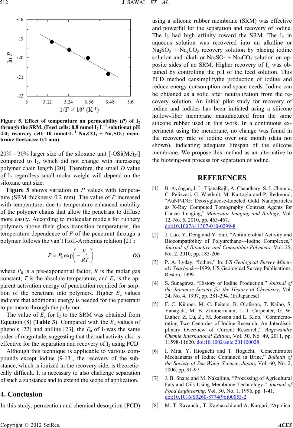 J. SAWAI ET AL. 512 Figure 5. Effect of temperature on permeability (P) of I2 through the SRM. (Feed cells: 0.8 mmol I2 L–1 solutionat pH 4.0; recovery cell: 10 mmol·L–1 Na2CO3 + Na2SO3; mem- brane thickness: 0.2 mm). 20% - 30% larger size of the siloxane unit [-OSi(Me)2-] compared to I2, which did not change with increasing polymer chain length [20]. Therefore, the small D value of I2 regardless small molar weight will depend on the siloxane unit si ze. Figure 5 shows variation in P values with tempera- ture (SRM thickness: 0.2 mm). The value of P increased with temperature, due to temperature-enhanced mobility of the polymer chains that allow the penetrant to diffuse more easily. According to molecular models for rubbery polymers above their glass transition temperatures, the temperature dependence of P of the penetrant through a polymer follows the van’t Hoff-Arrhenius relation [21]: a 0exp E RT PP (8) where P0 is a pre-exponential factor, R is the molar gas constant, T is the absolute temperature, and Ea is the ap- parent activation energy of penetration required for sorp- tion of the penetrant into polymers. Higher Ea values indicate that additional energy is needed for the penetrant to permeate through the polymer. The value of Ea for I2 to the SRM was obtained from Equation (8) (Table 3). Compared with the Ea values of phenols [22] and aniline [23], the Ea of I2 was the same order of magnitu de, sugg esting that th erma l ac tivit y also is effective for the separation and recovery of I2 using PCD. Although this technique is applicable to various com- pounds except iodine [9-13], the recovery of the sub- stance, which is ionized in the recovery side, is theoretic- cally difficult. It is necessary to also challenge separation of such a substance and to extend the scope of applicati on. 4. Conclusion In this study, permeation and chemical desorption (PCD) using a silicone rubber membrane (SRM) was effective and powerful for the separation and recovery of iodine. The I2 had high affinity toward the SRM. The I2 in aqueous solution was recovered into an alkaline or Na2SO3 + Na2CO3 recovery solution by placing iodine solution and alkali or Na2SO3 + Na2CO3 solution on op- posite sides of an SRM. Higher recovery of I2 was ob- tained by controlling the pH of the feed solution. This PCD method cansimplifythe production of iodine and reduce energy consumption and space needs. Iodine can be obtained as a solid after neutralization from the re- covery solution. An initial pilot study for recovery of iodine and iodides has been initiated using a silicone hollow-fiber membrane manufactured from the same silicone rubber used in this work. In a continuous ex- periment using the membrane, no change was found in the recovery rate of iodine over one month (data not shown), indicating adequate lifespan of the silicone membrane. We propose this method as an alternative to the blowing-out process for separation of iodine. REFERENCES [1] B. Aydogan, J. L. TijanaRajh, A. Chaudhary, S. J. Chmura, C. Pelizzari, C. Wietholt, M. Kurtoglu and P. Redmond, “AuNP-DG: Deoxyglucose-Labeled Gold Nanoparticles as X-Ray Computed Tomography Contrast Agents for Cancer Imaging,” Molecular Imaging and Biology, Vol. 12, No. 5, 2010, pp. 463-467. doi:10.1007/s11307-010-0299-8 [2] J. Luo, Y. Deng and Y. Sun, “Antimicrobial Activity and Biocompatibility of Polyurethane—Iodine Complexes,” Journal of Bioactive and Compatible Polymers, Vol. 25, No. 2, 2010, pp. 185-206 [3] P. A. Lyday, “Iodine,” In: US Geological Survey Miner- als Yearbook—1999, US Geological Survey Publications, Reston, 1999. [4] S. Sunagawa, “History of Iodine Production,” Journal of the Japanese Society for the History of Chemistry, Vol. 24, No. 4, 1997, pp. 281-294. (In Japanese) [5] F. C. Küpper, M. C. Feiters, B. Olofsson, T. Kaiho, S. Yanagida, M. B. Zimmermann, L. J. Carpenter, G. W. Luther, Z. Lu, Z., M. Jonsson and L. Kloo, “Commemo- rating Two Centuries of Iodine Research: An Interdisci- plinary Overview of Current Research,” Angewandte Chemie International Edition, Vol. 50, No. 49, 2011, pp. 11598-11620. doi:10.1002/anie.201100028 [6] I. Mita, Y. Hioguchi and T. Hoguchi, “Concentration Mechanisms of Iodine Contained in Brine,” Bulletin of the Society of Sea Water Science, Japan, Vol. 60, No. 2, 2006, pp. 91-97. [7] J. B. Snape and M. Nakajima, “Processing of Agricultural Fats and Oils Using Membrane Technology,” Journal of Food Engineering, Vol. 30, No. 1, 1996, pp. 1-41. doi:10.1016/S0260-8774(96)00053-2 [8] M. T. Ravanchi, T. Kaghazchi and A. Kargari, “Applica- Copyright © 2012 SciRes. ACES  J. SAWAI ET AL. 513 tion of Membrane Separation Processes in Petrochemical Industry: A Review,” Desalination, Vol. 235, No. 1-3, 2009, pp. 199-244. doi:10.1016/j.desal.2007.10.042 [9] M. Kikuchi, K. Sato and T. Minami, JP Patent 2001- 293472, 2001. [10] M. Kikuchi, K. Sato and T. Minami, JP Patent 2002- 331228, 2002. [11] J. Sawai, N. Ito, T. Minami and M. Kikuchi, “Separation of Low Volatile Organic Compounds, Phenol and Aniline Derivatives, from Aqueous Solution Using Silicone Rub- ber Membrane,” Journal of Membrane Science, Vol. 252, No. 1-2, 2005, pp. 1-7. doi:10.1016/j.memsci.2004.06.018 [12] J. Sawai, K. Higuchi, T. Minami and M. Kikuchi, “Re- moval and Permeation Characteristics of 4-Substituted Phenol and Aniline Derivatives in Aqueous Solution Us- ing a Silicone Rubber Membrane,” Chemical Engineering Journal, Vol. 152, No. 1, 2009, pp. 133-138. doi:10.1016/j.cej.2009.04.003 [13] J. Sawai, K. Sahara, T. Minami and M. Kikuchi, “Separa- tion of Pentachlorophenol in Aqueous Phase by Silicone Rubber Membrane,” Advances in Chemical Engineering and Science, Vol. 2, No. 3, 2012, pp. 372-378. doi:10.4236/aces.2012.23044 [14] F. C. Ferrei ra, S. Han a nd A. G. Livingston, “Recovery of Aniline from Aqueous Solution Using the Membrane Aromatic Recovery System,” Industrial & Engineering Chemistry Research, Vol. 41, No. 11, 2002, pp. 2766- 2774. doi:10.1021/ie010746l [15] F. C. Ferreira, S. Han, A. Boam, S. Zhang and A. G. Li- vingston, “Membrane Aro matic Recovery Sy stem (MARS): Lab Bench to Industrial Pilot Scale,” Desalination, Vol. 148, No. 1-3, 2002, pp. 267-273. doi:10.1016/S0011-9164(02)00709-9 [16] “Kagaku Daijiten,” Kyoritsu Shuppan, Tokyo, 1963, p. 447. [17] J. Hur, J. P. O’Connell, K. K. Bae, K. S. Kang and J. W. Kang,” Measurements and Correlation of Solid-Liquid Equilibria of the HI + I2+ H2O System,” Internatinal Journal of Hydrogen Energy, Vol. 36, No. 14, 2011, pp. 8187-8191. doi:10.1016/j.ijhydene.2011.04.125 [18] N. Watanabe and T. Miyauchi, “The Permeation of Iodine through a Diaphragm Type Liquid Membrane—The Dif- fusion Coefficient of Iodine in Poly (Dimethylsiloxane),” Kagaku Kogaku Ronbunshu, Vol. 2, No. 3, 1976, pp. 262- 265. (In Japanese) doi:10.1252/kakoronbunshu.2.262 [19] M. Imai, S. Furisaki and T. Miyauchi, “Separation of Volatile Materials by Gas Membrane,” Industrial & En- gineering Chemistry Process Design and Research, Vol. 21, No. 3, 1982, pp. 421-426. doi:10.1021/i200018a013 [20] N. Watanabe and T. Miyauchi, “Determination of Solu- bility Parameter For Siloxane Segment,” Journal of Che- mical Engineering of Japan, Vol. 6, No. 2, 1973, pp. 109- 114. doi:10.1252/jcej.6.109 [21] S. C. George, M. Knorgen and S. Thomas, “Effect of Nature and Extent Cross-Linking on Swelling and Me- chanical Behavior of Styrene-Butadiene Rubber Mem- brane,” Journal of Membrane Science, Vol. 163, No. 1, 1999, pp. 1-17. doi:10.1016/S0376-7388(99)00098-8 [22] S. Han, F. C. Ferreira and A. G. Livingston, “Membrane Aromatic Recovery System (MARS)—A New Membrane Process for the Recovery of Phenols from Wastewaters,” Journal of Membrane Science, Vol. 188, No. 1-3, 2001, pp. 219-233. doi:10.1016/S0376-7388(01)00377-5 [23] K. C. Farinas, L. Doh, S. Venkatramann and R. O. Potts, “Characterization of Solute Diffusion in a Polymer Using ATR-FTIR Spectroscopy and Bulk Transport Techniques,” Macromolecules, Vol. 27, No. 18, 1994, pp. 5220-5222. doi:10.1021/ma00096a055 Copyright © 2012 SciRes. ACES
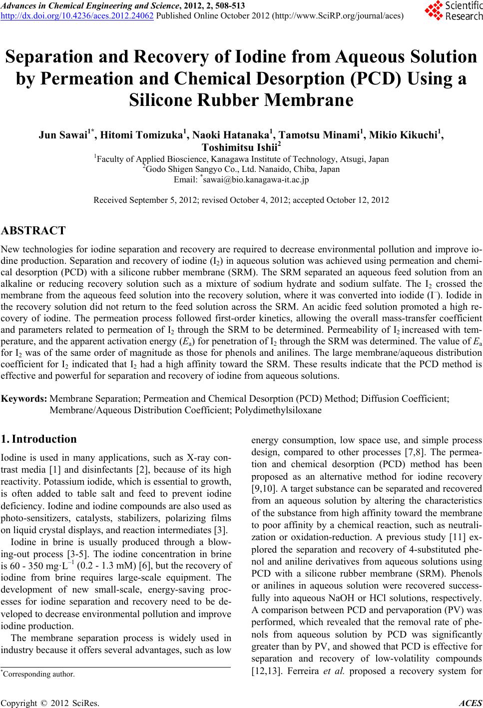
|