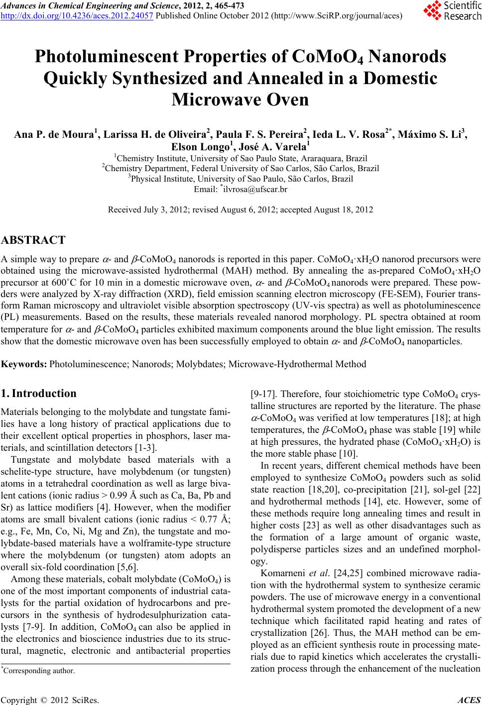
 Advances in Chemical Engineering and Science, 2012, 2, 465-473 http://dx.doi.org/10.4236/aces.2012.24057 Published Online October 2012 (http://www.SciRP.org/journal/aces) Photoluminescent Properties of CoMoO4 Nanorods Quickly Synthesized and Annealed in a Domestic Microwave Oven Ana P. de Moura1, Larissa H. de Oliveira2, Paula F. S. Pereira2, Ieda L. V. Rosa2*, Máximo S. Li3, Elson Longo1, José A. Varela1 1Chemistry Institute, University of Sao Paulo State, Araraquara, Brazil 2Chemistry Department, Federal University of Sao Carlos, São Carlos, Brazil 3Physical Institute, University of Sao Paulo, São Carlos, Brazil Email: *ilvrosa@ufscar.br Received July 3, 2012; revised August 6, 2012; accepted August 18, 2012 ABSTRACT A simple way to prepare - and -CoMoO4 nanorods is reported in this paper. CoMoO4·xH2O nanorod precursors were obtained using the microwave-assisted hydrothermal (MAH) method. By annealing the as-prepared CoMoO4·xH2O precursor at 600˚C for 10 min in a domestic microwave oven, - and -CoMoO4 nanorods were prepared. These pow- ders were analyzed by X-ray diffraction (XRD), field emission scanning electron microscopy (FE-SEM), Fourier trans- form Raman microscopy and ultraviolet visible absorption spectroscopy (UV-vis spectra) as well as photoluminescence (PL) measurements. Based on the results, these materials revealed nanorod morphology. PL spectra obtained at room temperature for - and -CoMoO4 particles exhibited maximum components around the blue light emission. The results show that the domestic microwave oven has been successfully employed to obtain - and -CoMoO4 nanoparticles. Keywords: Photoluminescence; Nanorods; Molybdates; Microwave-Hydrothermal Method 1. Introduction Materials belonging to the molybdate and tungstate fami- lies have a long history of practical applications due to their excellent optical properties in phosphors, laser ma- terials, and scintillation detectors [1-3]. Tungstate and molybdate based materials with a schelite-type structure, have molybdenum (or tungsten) atoms in a tetrahedral coordination as well as large biva- lent cations (ionic radius > 0.99 Å such as Ca, Ba, Pb and Sr) as lattice modifiers [4]. However, when the modifier atoms are small bivalent cations (ionic radius < 0.77 Å; e.g., Fe, Mn, Co, Ni, Mg and Zn), the tungstate and mo- lybdate-based materials have a wolframite-type structure where the molybdenum (or tungsten) atom adopts an overall six-fold coordination [5,6]. Among these materials, cobalt molybdate (CoMoO4) is one of the most important components of industrial cata- lysts for the partial oxidation of hydrocarbons and pre- cursors in the synthesis of hydrodesulphurization cata- lysts [7-9]. In addition, CoMoO4 can also be applied in the electronics and bioscience industries due to its struc- tural, magnetic, electronic and antibacterial properties [9-17]. Therefore, four stoichiometric type CoMoO4 crys- talline structures are reported by the literature. The phase -CoMoO4 was verified at low temperatures [18]; at high temperatures, the -CoMoO4 phase was stable [19] while at high pressures, the hydrated phase (CoMoO4·xH2O) is the more stable phase [10]. In recent years, different chemical methods have been employed to synthesize CoMoO4 powders such as solid state reaction [18,20], co-precipitation [21], sol-gel [22] and hydrothermal methods [14], etc. However, some of these methods require long annealing times and result in higher costs [23] as well as other disadvantages such as the formation of a large amount of organic waste, polydisperse particles sizes and an undefined morphol- ogy. Komarneni et al. [24,25] combined microwave radia- tion with the hydrothermal system to synthesize ceramic powders. The use of microwave energy in a conventional hydrothermal system promoted the development of a new technique which facilitated rapid heating and rates of crystallization [26]. Thus, the MAH method can be em- ployed as an efficient synthesis route in processing mate- rials due to rapid kinetics which accelerates the crystalli- zation process through the enhancement of the nucleation *Corresponding author. C opyright © 2012 SciRes. ACES  A. P. DE MOURA ET AL. 466 rate. In this method, chemical reaction is related to the effect of microwave radiation during the experimental procedure which interacts with the permanent dipole of the solvent and induces molecular vibration and pro- motes rapid heating as a result of molecular rotation [27]. Therefore, in this study, CoMoO4·xH2O precursors were prepared by the MAH method and then heat treated using microwave radiation to form the desired - and -CoMoO4 phases. These materials were chemically, structurally and morphologically investigated by XRD, FE-SEM, (UV-vis) and Raman spectroscopy; their opti- cal properties were also investigated by PL measure- ments at room temperature. 2. Experimental Section 2.1. Synthesis of the Precursors In a typical procedure, 2 mmol of sodium molybdate solution was dissolved in 50 mL of distilled water. Then, 2 mmol of cobalt nitrate hexaydrate was dissolved in 50 mL of deionized water which was slowly added to the sodium molybdate solution under magnetic stirring which produced a homogeneous solution (pH = 6). The reaction mixture was transferred to a Teflon-lined stain- less autoclave which was finally sealed and placed in the MH system using 2.45 GHz microwave radiation with maximum power of 800 W. MH conditions were kept at 140˚C for 1, 2, 4, 8, 16 and 32 minutes. Then, the auto- clave was naturally cooled to room temperature. These as-prepared purple precursor powders were labeled as P1, P2, P4, P8 P16 and P32, respectively. Precursors P1, P2, P4, P8, P16 and P32 were water washed several times until a neutral pH was obtained and then dried at 60˚C for 8 h under atmospheric air in a conventional furnace. 2.2. Synthesis of - and -CoMoO4 Powders CoMoO4 powders were obtained from the thermal de- composition of precursors P1, P2, P4, P8, P16 and P32. These precursor powders were placed in ceramic cruci- bles and heated in a microwave sintering furnace at 600˚C for 10 minutes. The calcinated brown-like pow- ders were labeled D1, D2, D4, D8 D16 and D32 samples, respectively. 2.3. Characterizations Precursors P1, P2, P4, P8 P16 and P32 and - and -CoMoO4 powders D1, D2, D4, D8 D16 and D32 were characterized by powder XRD using a Rigaku-DMax 2500PC, (Japan) with Cu Kα radiation (λ = 1.540598 Å) in the 2θ range from 5˚ to 75˚ using a scanning rate of 0.02˚/min. The morphologies of the samples were veri- fied using FE-SEM (Jeol JSM 6330F). The particle size of precursors and CoMoO4 powders were determined using FE-SEM images and were calculated using the Image J. program. UV-vis spectra were taken using Cary 5G (Varian, USA) equipment in the diffuse reflection mode. The thermal decomposition of the precursor pow- ders was studied by thermogravimetric analysis (TGA/ DTA) on a TGA 2050 thermal analysis device (American TA Corporation). TGA determination was carried out in air at a heating rate of 20˚C/min−1 in the range from room temperature to 900˚C. PL precursor measurements were taken in a Thermal Jarrel-Ash Monospec 27 monochromator and a Hamama- tsu R446 photomultiplier. The 350.7 nm exciting wave- length of a krypton ion laser (Coherent Innova) was used with the nominal output power of the laser power kept at 200 mW. All the measurements were taken at room tem- perature. 3. Results and Discussion 3.1. Precursor Nanorods 3.1.1. XRD Patterns of the Precursor Nanorods Figure 1 shows XRD patterns of precursor P1 from MAH processing at 140˚C for 1 minute. The results revealed that MAH treatment led to the formation of a pure phase CoMoO4·xH2O with good crystallinity (see Figure 1). All reflection peaks of different samples prepared at different times can be easily indexed as the Co- MoO4·xH2O phase of the purple powders. The formation of CoMoO4·xH2O pure powders with a monoclinic structure and cell parameters of = 9.501 Å, b = 8.897 Å, c = 7.751 Å and = 113.83˚ (Joint Committee on Pow- der Diffraction Standards (JCPDS) N˚. 26-0477) was verified. These observations confirm that MH processing results in the formation of a product based on XRD pat- terns of the as-prepared P1 powder obtained from the MAH method at 140˚C for 1 min. Figure 1. XRD patterns of the precursor P1 microwave- hydrothermal assisted at 140˚C for 1 minute. Copyright © 2012 SciRes. ACES  A. P. DE MOURA ET AL. 467 3.1.2. FE-SEM Images of the Precursors Nanorods Figure 2(A) shows FEG-SEM images of the P1 powders. This sample consists of large-scale and homogeneous CoMoO4·xH2O particles with morphology-like nanorods. This morphology was observed for all P1, P2, P4, P8 P16 and P32 precursors. Figure 2(B) is a histogram with the calculated average thickness of these nanorods evaluated as 100 - 300 nm. Nanorods lengths were determined as ca. 1 - 3 m. All other samples prepared at different times showed similar morphology. 3.1.3. TGA Curves of Precursor Nanorods The thermal behavior of the P1 precursor nanostructure was examined by TGA measurements (see Figure 3). The TGA curve shows that the precursor decomposi- tion occurs in two steps: 1) in a temperature range of 84˚C and 165˚C; and 2) between 168˚C and 450˚C. A total weight loss of 5.75% was obtained which, accord- ing to Ding and co-workers [6], is largely ascribed to water loss corresponding to the water content in the hy- drated product. These researchers also observed these two steps where the desired CoMoO4 crystalline structure occurred at 45˚C. Thus, the 600˚C temperature was cho- sen to heat treat precursor powders to obtain the pure CoMoO4. Figure 2. (A) FEG-SEM micrographies images and (B) average thickness distribution of the particles (nm) of the CoMoO4·xH2O powder obtained by the microwave-hydro- thermal assisted method (MH) at 140˚C for 1 min (P1). Figure 3. TGA curves of the as-prepared CoMoO4·xH2O precursor powder obtained from by the microwave-hydro- thermal assisted method (MH) at 140˚C by 1 min. 3.2. - and -CoMoO4 3.2.1. XRD Patterns of - and -CoMoO4 Powders XRD patterns of - and -CoMoO4 phases obtained by thermal decomposition of the precursor (CoMoO4·xH2O) are shown in Figure 4. XRD patterns reveal that all calcined samples have well defined narrow diffraction peaks of two phases that are ordered at long range. -CoMoO4 has a monoclinic structure with a space group of C2/m (Joint Committee on Powder Diffraction Standards) (JCPDS N˚. 25.1434), and -CoMoO4 has a monoclinic structure with a space group of C2/m (JCPDS No. 21-0868), respectively. 3.2.2. R aman Spectra of - and -CoMoO4 Powders Figure 5 shows Raman spectra of D1, D2, D4, D8 D16 and D32 samples, respectively. Raman spectra collected at room temperature showed that both and phases have similar vibrational modes related to the CoMoO4 with a space group of C2/m. These vibrational modes are observed at 330, 369, 698, 815, 879, and 941 cm–1. The Raman mode at 941 cm–1 is associated with the symmet- ric stretching mode of Mo-O. The bands located at 879 cm–1 and 815 cm–1 correspond to asymmetric stretching modes of oxygen in binding O-Mo-O. The bands ob- served at 330 cm–1 and 369 cm–1 are related to asymmet- ric and symmetric bending modes of the O-Mo-O, respec- tively. The band located at 698 cm–1 can be attributed to the symmetric stretching of the Co-O-Mo bond (see Ta- ble 1). Figure 5 illustrates that all Raman spectra have the same features. The results obtained are in agreement with the literature [28], and the small variations in the positions of the vibrational modes can be associated with the me- thod of preparation, crystal size, morphology and strength of interaction between the ions and the degree of struc- tural order-disorder of these materials. Copyright © 2012 SciRes. ACES  A. P. DE MOURA ET AL. 468 Figure 4. XRD patterns of the (a) D1, (b) D2, (c) D4, (d) D8, (e) D16 and (f) D32 powders prepared by thermal decompo- sition of the CoMoO4·xH2O precursors at 600˚C for 10 min- utes. Figure 5. Raman spectra of the (a) D 1, (b) D 2, (c) D 4, (d) D 8, (e) D 16 and (f) D 32 samples. Table 1. Relative positions of the Raman active modes for the samples of - and -CoMoO4. Symbol Position Vibrational Mode P6 941 cm–1 Symmetric stretch O-Mo-O P5, P4 879 cm–1 e 815 cm–1 Assimmetric stretch O-Mo-O P3 698 cm–1 Symmetric stretch Co-Mo-O P2 330 cm–1 Assimmetric torsional mode O-Mo-O P1 369 cm–1 Symmetric torsional mode O-Mo-O 3.2.3. FE-SEM An al ysi s of - and -CoMoO4 Powders Crystal structures of - and -CoMoO4 rods annealed at 600˚C were characterized by FE-SEM. Figure 6 shows FE-SEM images of (a) D1, (b) D2, (c) D4, (d) D8, (e) D16 and (f) D32 powders, respectively. The nanorod-like morphology of - and -CoMoO4 was similar to the precursors (Figures 2 and 6) which indicate that this method is a good approach to prepare powders with controlled morphology. Figure 7 shows the average thickness distribution of particles for samples (A) D1, (B) D2, (C) D4, (D) D8, (E) D16 and (F) D32. According to these graphics all parti- cles have the same thickness being which is evaluated as ca. 250 and 350 nm. Particle lengths were determined to be between 2 to 4 μm. 3.3.4. Ultr a vio l e t-Vi si bl e Absorption Spect roscopy Analyses The optical energy gap is associated with the degree of structural order and disorder of the materials in a medium range. The order/disorder ratio leads to different defect densities in the material which results in different distri- butions of intermediate levels of energy between the va- lence (VB) and conduction band (CB). Most crystalline materials exhibit a greater degree of organization when compared to the less crystalline materials with more structural defects. Therefore, these materials exhibit a high optical energy gap value because they have small intermediate energy levels between the VB and CB [29]. The optical band gap energy (Eg) of - and -CoMoO4 nanorods was estimated by the method proposed by Wood and Tauc [30]. According to these authors the Eg is associated with absorbance and photon energy by the following equation: m g hhE , (1) where is the absorbance, h is Planck’s constant, is the frequency, Eg is the optical band gap and m is a con- stant associated with the different types of electronic transitions (m = 1/2, 2, 3/2 or 3 for direct allowed, indi- rect allowed, direct forbidden and indirect forbidden transitions, respectively). In this case, Eg values of the powders were evaluated by extrapolating the linear por- tion of the curve or tail. The m value suggested in our work is 2 which indicate an indirect allowed transition. The Uv-vis absorbance spectra of the samples as well as the gap values are presented in Figure 8. The value of the Eg was quantified from spectra in Figure 8. Samples D1, D2, D4, D8, D16 and D32 have respectively gap values of 2, 1.8, 2.1, 2.1, 2.4, and 2.0 eV. The results obtained in this study are in accordance with the value of 1.8 eV already published [31]. The small difference in our results is probably due to quantum size effects as well as reaction conditions of the medium. Both effects promote different structural defects in the materials. The preparation time for precursors with microwave irradia- tion results changes Eg values. A pronounced difference between samples D2 min and D16 min is evident. Ac- cording to another report [1], three different charge states Copyright © 2012 SciRes. ACES  A. P. DE MOURA ET AL. ACES 469 V.. V X V .. 3.3.5. PL Measurements occurring in oxygen vacancies in molybdenum are [MoO3·], [MoO3·O], and [MoO3·O] complex states. The [MoO3·O], complex state has two paired electrons ↑↓ and is a neutral relative to the lattice. The single ionized [MoO3·O V], complex state has one un- paired electron ↑, and the [MoO3·O V] complex state did not trap any electrons and was doubly positively charged with respect to the lattice. The authors speculate that these oxygen vacancies induced new energy in the band gap and were attributable to the molybdenum-oxygen complex vacancy centers. In this case, the interaction of these clusters with microwave irradiation results in distortions in the angles and lengths of bonds which generates different degrees of defects and different distributions of intermediate energy levels between VB and CB. X O VFigure 9 illustrates PL spectra of D1, D2, D4, D8 D16 and D32 powders at room temperature using excitation of a krypton laser source at 350.7 nm. These PL spectra exhibited a broad band in the range of 300 - 600 nm which is ascribed to a multiphoton process where many intermediate levels of energy are involved in the PL process where relaxation occurs by several paths. PL spectra observed for all powders show a maximum emis- sion located at 450 nm (blue region of the electromag- netic spectrum). According to Wu et al. [32,33], the emission band shape might be explained by considering the Jahn-Teller active vibration modes of T2 symmetry that influence the [MoO4]2− complex anion of slightly distorted tetrahedral symmetry which leads to a struc- ured absorption band for the A1-T1(2) transition. t Figure 6. FE-SEM micrographies - and -CoMoO4 samples: (A) D 1, (B) D 2, (C) D 4, (D) D 8, (E) D 16 and (F) D 32. Copyright © 2012 SciRes.  A. P. DE MOURA ET AL. 470 Figure 7. Average thickne ss distri bution of the partic les (nm) for the samples: (A) D1, (B) D2, (C) D4, (D) D8, (E) D16 and (F) D32. Figure 8. UV-vis absorbance spectra of the samples: (A) D1, (B) D2, (C) D4, (D) D8, (E) D16 and (F) D32. Copyright © 2012 SciRes. ACES  A. P. DE MOURA ET AL. Copyright © 2012 SciRes. ACES 471 of energy within the band gap. These energy levels are basically composed of oxygen 2p states (near the valence band) and Mo 4d states (below the conduction band). In these cases, polarizations induce a symmetry breaking and localized energy levels that favor the trapping of electrons. For CoMoO4 powders synthesized in this study, the ratio of order and disorder can result from the inter- action of microwave energy with [MoO3] and [MoO4] clusters. The interaction of these clusters with microwave radiation produces the formation of defects and/or distor- tions in these materials. The - and -CoMoO4 nanorods have a broad band emission typical of systems where relaxation processes occur by different paths which involve intermediary lev- els in the “band gap”. Thus, the decomposition of these broad bands (see Figure 10) was used to obtain informa- tion on the PL response influenced by electronic transi- tions. The decomposition was performed using the Peak- Fit Program (version 4.05), and the Gaussian function was used successfully to fit the PL peaks and tuning pa- rameters, including peak positions and corresponding areas (see Table 2 ). In this study, PL curves can be com- posed of three components: 1) the blue component (with a maximum at around 440 nm); 2) the blue-green com- ponent (with a maximum at around 475 nm); and the green component (with a maximum at around 525 nm). n analysis of the evolution of the PL emission of D1, Figure 9. PL spectra of the samples - and -CoMoO4: (A) D1, (B) D2, (C) D4, (D) D8, (E) D16 and (F) D32. Figure 9 also shows that the precursor processing time influenced PL behavior due to the verified differences in emission intensities and a slight shift in the maximum intensities positions. The PL maximum emission intensity is related to the effects of structural order and disorder in the material which result in different electron transfer processes due to different distributions of intermediate levels of energy between the VB and CB. Studies of molybdates PL [1] suggest that distorted clusters of [MoO3] and [MoO4] in the network lead to the formation of intermediate levels A Figure 10. Deconvolution of the PL spectra of for the samples - and -CoMoO4: (A) D1, (B) D2, (C) D4, (D) D8, (E) D16 and (F) D32.  A. P. DE MOURA ET AL. 472 Table 2. Data obtained by the decomposition of PL bands of - and -CoMoO4 samples. Peak 1 Peak 2 Peak 3 Sample PL emission maximus (nm) (nm) Área (%) (nm) Área (%) (nm) Área (%) D 1 455 445 54.7 483 30.0 529 15.2 D 2 453 442 52.5 478 35.8 526 11.5 D 4 453 442 51.5 478 34.3 525 14.1 D 8 453 438 46.2 475 39.2 521 14.5 D 16 451 440 49.6 477 36.5 525 13.8 D 32 455 442 51.2 478 36.3 526 12.3 D2, D4, D8 D16 and D32 powders (see Table 2) reveals that all samples exhibit a PL emission maximum at ca. 455 nm (blue emission) which indicates that the charge transference process as well as the trapping of electrons occurs because of a greater contribution of shallow holes rather than deep holes [33]. 4. Conclusion A synthesis process utilizing the MAH method for a short time was successful in obtaining precursors of both - and -CoMoO4 Nanorods. XRD patterns and Raman spectra at room temperature showed that these powders have both and phases related to the CoMoO4 with a space group of C2/m. These materials contain nanorod morphologies, and all samples exhibit a PL emission maximum at ca. 455 nm (in the blue emission) which indicates that the charge transference process as well as the trapping of electrons occurs because of a greater con- tribution of shallow holes rather than deep holes. 5. Acknowledgements The authors are grateful for the financial support of Bra- zilian agencies CNPq, FAPESP and CAPES. REFERENCES [1] A. P. A. Marques, V. M. Longo, D. M. A. de Melo, P. S. Pizani, E. R. Leite, J. A. Varela and E. Longo, “Shape Controlled Synthesis of CaMoO4 Thin Films and Their Photoluminescence Property,” Journal of Solid State Chemistry, Vol. 181, No. 5, 2008, pp. 1249-1257. doi:10.1016/j.jssc.2008.01.051 [2] N. Klassen, S. Shmurak, B. Red’kin, B. Ille, M. Lebeau, P. Lecoq and M. Schneegans, “Correlations between Struc- tural and Scintillation Characteristics of Lead and Cad- mium Tungstates,” Nuclear Instruments and Methods in Physics Research Section A: Accelerators, Spectrome- ters, Detectors and Associated Equipment, Vol. 486, No. 1- 2, 2002, pp. 431-436. doi:10.1016/S0168-9002(02)00748-9 [3] F. A. Danevich, A. S. Georgadze, V. V. Kobychev, B. N. Kropivyansky, V. N. Kuts, A. S. Nikolaiko, V. I. Tretyak and Y. Zdesenko, “The Research of 2β Decay of 116Cd with Enriched 116CdWO4 Crystal Scintillators,” Physics Letters B, Vol. 344, No. 1-4, 1995, pp. 72-78. doi:10.1016/0370-2693(94)01528-K [4] B. G. Hyde and S. Andersson, “Inorganic Crystal Struc- tures,” Crystal Research and Technology, Vol. 25, 1990, p. 676. [5] A. P. Young and C. H. Schwartz, “High-Pressure Synthe- sis of Molybdates with the Wolframite Structure,” Sci- ence, Vol. 141, No. 3578, 1963, pp. 348-349. doi:10.1126/science.141.3578.348 [6] Y. Ding, Y. Wan, Y. L. Min, W. Zhang and S. H. Yu, “General Synthesis and Phase Control of Metal Moly- bdate Hydrates MMoO4·nH2O (M = Co, Ni, Mn, n = 0, 3/4, 1) Nano/Microcrystals by a Hydrothermal Approach: Magnetic, Photocatalytic, and Electrochemical Proper- ties,” Inorganic Chemistry, Vol. 47, No. 17, 2008, pp. 7813- 7823. doi:10.1021/ic8007975 [7] J. E. Miller, N. B. Jackson, L. Evans, A. G. Sault and M. M. Gonzales, “The Formation of Active Species for Oxi- dative Dehydrogenation of Propane on Magnesium Mo- lybdates,” Catalysis Letters, Vol. 58, No. 2-3,1999, pp. 147-152. doi:10.1023/A:1019013514105 [8] J. A. Rodriguez, S. Chaturvedi, J. C. Hanson and J. L. Brito, “Reaction of H2 and H2S with CoMoO4 and Ni- MoO4: TPR, XANES, Time-Resolved XRD, and Mo- lecular-Orbital Studies,” Journal of Physical Chemistry B, Vol. 103, No. 5, 1999, pp. 770-781. doi:10.1021/jp983115m [9] J. Zhao, Q. Wu and M. Wen, “Temperature-Controlled Assembly and Morphology Conversion of Co MoO4·3/4 H2O Nano-Superstructured Grating Materials,” Journal of Materials Science, Vol. 44, No. 23, 2009, pp. 6356-6362. doi:10.1007/s10853-009-3876-y [10] K. Eda, Y. Uno, N. Nagai, N. Sotani and M. S. Whitting- ham, “Crystal Structure of Cobalt Molybdate Hydrate Co- MoO4·nH2O,” Journal of Solid State Chemistry, Vol. 178, No. 9, 2005, pp. 2791-2797. doi:10.1016/j.jssc.2005.06.014 [11] J. A. Rodriguez, S. Chaturvedi, J. C. Hanson, A. Albor- noz and J. L. Brito, “Electronic Properties and Phase Transformations in CoMoO4 and NiMoO4: XANES and Time-Resolved Synchrotron XRD Studies,” Journal of Physical Chemistry B, Vol. 102, No. 8, 1998, pp. 1347- 1355. doi:10.1021/jp972137q [12] H. Ehrenberg, M. Wiesmann, J. García-Jaca, H. Weitzel and H. Fuess, “Magnetic Structures of the High-Pressure Copyright © 2012 SciRes. ACES  A. P. DE MOURA ET AL. 473 Modifications of CoMoO4 and CuMoO4,” Journal of Magnetism Materials, Vol. 182, No. 1-2, 1998, pp. 152- 160. doi:10.1016/S0304-8853(97)01008-1 [13] Y. M. Kong, J. Peng, Z. F. Xin, B. Xue, B. X. Dong, F. S. Shen and L. Li, “Selective Synthesis and Novel Properties of Single Crystalline α-CoMoO4 Nanorods/Nano Whisk- ers,” Materials Letters, Vol. 61, No. 10, 2007, pp. 2109- 2112. doi:10.1016/j.matlet.2006.08.028 [14] M. Wiesmann, H. Ehrenberg, G. Wltschek, P. Zinn, H. Weitzel and H. Fuess, “Crystal Structures and Magnetic Properties of the High-Pressure Modifications of Co- MoO4 and NiMoO4,” Journal of Magnetism of Magnet- ism Materials, Vol. 150, No. 1, 1995, pp. L1-L4. doi:10.1016/0304-8853(95)00516-1 [15] Y. Y. Meng and Z. X. Xiong, “Preparation of Molybdates with Antibacterial Property,” Key Engineering Materials, Vol. 368-372, 2008, pp. 1516-1518. doi:10.4028/www.scientific.net/KEM.368-372.1516 [16] C. Mazzocchia, C. Aboumrad, C. Diagne, E. Tempesti, J. M. Herrmann and G. Thomas, “On the NiMoO4 Oxi- dative Dehydrogenation of Propane to Propene: Some Physical Correlations with the Catalytic Activity,” Cata- lysis Letters, Vol. 10, No. 3-4, 1991, pp.181-191. doi:10.1007/BF00772070 [17] J. L. Brito and A. L. Barbosa, “Effect of Phase Composi- tion of the Oxidic Precursor on the HDS Activity of the Sulfided Molybdates of Fe(II), Co(II), and Ni(II),” Jour- nal of Catalysis, Vol. 171, No. 2, 1997, pp. 467-475. doi:10.1006/jcat.1997.1796 [18] G. W. Smith, “The Crystal Structures of Cobalt Molyb- date CoMoO4 and Nickel Molybdate NiMoO4,” Acta Crystallographica, Vol. 15, 1962, pp. 1054-1057. doi:10.1107/S0365110X62002765 [19] A. W. Sleight and B. L. Chamberland, “Transition Metal Molybdates of the Type AMoO4,” Inorganic Chemistry, Vol. 7, No. 8, 1968, pp. 1672-1675. doi:10.1021/ic50066a050 [20] K. Sieber, R. Kershae, K. Dwight and A. Wold, “De- pendence of Magnetic Properties on Structure in the Sys- tems Nickel(II) Molybdate(VI) and Cobalt(II) Molyb- date(VI),” Inorganic Chemistry, Vol. 22, No. 19, 1983, pp. 2667-2669. doi:10.1021/ic00161a004 [21] C. Mazzocchia, C. Aboumrad, C. Diagne, E. Tempesti, J. M. Herrmann and G. Thomas, “On the NiMoO4 Oxi- dative Dehydrogenation of Propane to Propene: Some Physical Correlations with the Catalytic Activity,” Cata- lysis Letters, Vol. 10, No. 3-4, 1991, pp. 181-191. [22] A. Maione and M. Devilers “Solid Solutions of Ni and Co Molybdates in Silica-Dispersed and Bulk Catalysts Pre- pared by Sol-Gel and Citrate Methods,” Journal of Solid State Chemistry, Vol. 177, No. 7, 2004, pp. 2339-2349. doi:10.1016/j.jssc.2004.03.022 [23] J. Bi, C.-H. Cui, X. Lai, F. Shi and D.-J. Gao, “Synthesis of Luminescent SrMoO4 Thin Films by a Non-Reversible Galvanic Cell Method,” Materials Research Bulletin, Vol. 43, No. 3, 2008, pp. 743-747. doi:10.1016/j.materresbull.2007.03.021 [24] S. Komarneni, R. Roy and Q. H. Li, “Microwave-Hydro- thermal Synthesis of Ceramic Powders,” Materials Re- search Bulletin, Vol. 27, No. 12, 1992, pp. 1393-1405. doi:10.1016/0025-5408(92)90004-J [25] S. Komarneni, Q. H. Li and R. Roy, “Microwave-Hydro- thermal Processing for Synthesis of Layered and Network Phosphates,” Journal of Materials Chemistry, Vol. 4, 1994, pp. 1903-1906. doi:10.1039/jm9940401903 [26] G. J. Wilson, A. S. Matijasevich, D. R. G. Mitchell, J. C. Schulz and G. D. Will, “Modification of TiO2 for En- hanced Surface Properties: Finite Ostwald Ripening by a Microwave Hydrothermal Process,” Langmuir, Vol. 22, No. 5, 2006, pp. 2016-2027. doi:10.1021/la052716j [27] J. C. Sczancoski, L. S. Cavalcante, M. R. Joya, J. A. Varela, P. S. Pizani and E. Longo, “SrMoO4 Powders Processed in Microwave-Hydrothermal: Synthesis, char- acterization and Optical Properties,” Chemical Engineer- ing Journal, Vol. 140, No. 1-3, 2008, pp. 632-637. doi:10.1016/j.cej.2008.01.015 [28] M. Abdel-Dayem Hany, “Dynamic Phenomena during Reduction of α-NiMoO4 in Different Atmospheres: In- situ Thermo-Raman Spectroscopy Study,” Industrial & Engineering Chemistry Research, Vol. 46, No. 8, 2007, pp. 2466-2472. doi:10.1021/ie0613467 [29] L. S. Cavalcante, J. C. Sczancoski, L. F. Lima Jr., J. W. M. Espinosa, P. S. Pizani, J. A. Varela and E. Longo, “Syn- thesis, Characterization, Anisotropic Growth and Photo- luminescence of BaWO4,” Crystal Growth & Design, Vol. 9, No. 2, 2009, pp. 1002-1012. doi:10.1021/cg800817x [30] D. L. Wood and J. Tauc, “Weak Absorption Tails in Amor- phous Semiconductors,” Physical Review B, Vol. 5, No. 8, 1972, pp. 3144-3151. doi:10.1103/PhysRevB.5.3144 [31] P. K. Pandey, N. S. Bhave and R. B. Kharat, “Structural, Optical, Electrical and Photovoltaic Electrochemical Stu- dies of Cobalt Molybdate Thin Films,” Indian Journal of Pure & Applied Physics, Vol. 44, 2006, pp. 52-28. [32] A. P. A. Marques, F. V. Motta, E. R. Leite, P. S. Pizani, J. A. Varela, E. Longo and D. M. A. de Melo, “Evolution of Photoluminescence as a Function of the Structural Order or Disorder in CaMoO4 Nanopowders,” Journal of Ap- plied Physics, Vol. 104, No. 4, 2008, Article ID: 043505. doi:10.1063/1.2968388 [33] X. Wu, J. Du, H. Li, M. Zhang, B. Xi, H. Fan, Y. Zhu and Y. Qian, “Aqueous Mineralization Process to Synthesize Uniform Shuttle-Like BaMoO4 Microcrystals at Room Temperature,” Journal of Solid State Chemistry, Vol. 180, No. 11, 2007, pp. 3288-3295. doi:10.1016/j.jssc.2007.07.010 Copyright © 2012 SciRes. ACES
|