Paper Menu >>
Journal Menu >>
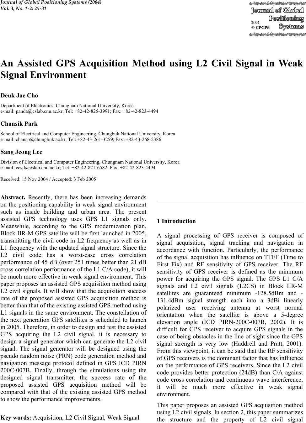 Journal of Global Positioning Systems (2004) Vol. 3, No. 1-2: 25-31 An Assisted GPS Acquisition Method using L2 Civil Signal in Weak Signal Environment Deuk Jae Cho Department of Electronics, Chungnam National University, Korea e-mail: panda@cslab.cnu.ac.kr; Tel: +82-42-825-3991; Fax: +82-42-823-4494 Chansik Park School of Electrical and Computer Engineering, Chungbuk National University, Korea e-mail: chansp@chungbuk.ac.kr; Tel: +82-43-261-3259; Fax: +82-43-268-2386 Sang Jeong Lee Division of Electrical and Computer Engineering, Chungnam National University, Korea e-mail: eesjl@cslab.cnu.ac.kr; Tel: +82-42-821-6582; Fax: +82-42-823-4494 Received: 15 Nov 2004 / Accepted: 3 Feb 2005 Abstract. Recently, there has been increasing demands on the positioning capability in weak signal environment such as inside building and urban area. The present assisted GPS technology uses GPS L1 signals only. Meanwhile, according to the GPS modernization plan, Block IIR-M GPS satellite will be first launched in 2005, transmitting the civil code in L2 frequency as well as in L1 frequency with the updated signal structure. Since the L2 civil code has a worst-case cross correlation performance of 45 dB (over 251 times better than 21 dB cross correlation performance of the L1 C/A code), it will be much more effective in weak signal environment. This paper proposes an assisted GPS acquisition method using L2 civil signals. It will show that the acquisition success rate of the proposed assisted GPS acquisition method is better than that of the existing assisted GPS method using L1 signals in the same environment. The constellation of the next generation GPS satellites is scheduled to launch in 2005. Therefore, in order to design and test the assisted GPS acquiring the L2 civil signal, it is necessary to design a signal generator which can generate the L2 civil signal. The signal generator will be designed using the pseudo random noise (PRN) code generation method and navigation message protocol defined in GPS ICD PIRN 200C-007B. Finally, through the simulations using the designed signal transmitter, the success rate of the proposed assisted GPS acquisition method will be compared with that of the existing assisted GPS method to show the performance improvements. Key words: Acquisition, L2 Civil Signal, Weak Signal 1 Introduction A signal processing of GPS receiver is composed of signal acquisition, signal tracking and navigation in accordance with function. Particularly, the performance of the signal acquisition has influence on TTFF (Time to First Fix) and RF sensitivity of GPS receiver. The RF sensitivity of GPS receiver is defined as the minimum power for acquiring the GPS signal. The GPS L1 C/A signals and L2 civil signals (L2CS) in Block IIR-M satellites are guaranteed minimum -128.5dBm and - 131.4dBm signal strength each into a 3dBi linearly polarized user receiving antenna at worst normal orientation when the satellite is above a 5-degree elevation angle (ICD PIRN-200C-007B, 2002). It is difficult for GPS receiver to acquire GPS signals in the case of being obstacles in the line of sight since the GPS signal strength is very low (Haddrell and Pratt, 2001). From this viewpoint, it can be said that the RF sensitivity of GPS receivers is the dominant factor that has influence on the performance of GPS receivers. Since the L2 civil code provides better protection (24dB) than C/A against code cross correlation and continuous wave interference, it will be much more effective in weak signal environment. This paper proposes an assisted GPS acquisition method using L2 civil signals. In section 2, this paper summarizes the structure and the property of L2 civil signal 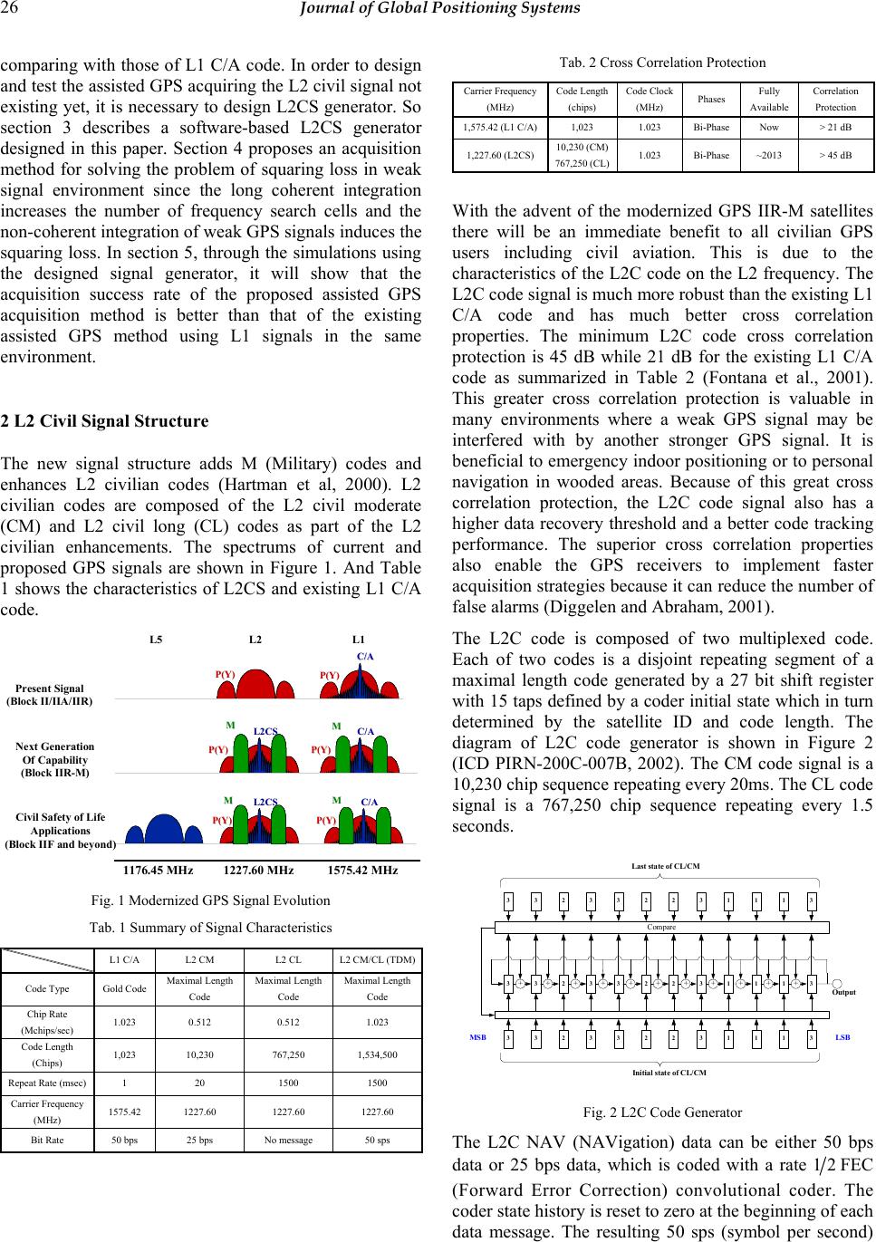 26 Journal of Global Positioning Systems comparing with those of L1 C/A code. In order to design and test the assisted GPS acquiring the L2 civil signal not existing yet, it is necessary to design L2CS generator. So section 3 describes a software-based L2CS generator designed in this paper. Section 4 proposes an acquisition method for solving the problem of squaring loss in weak signal environment since the long coherent integration increases the number of frequency search cells and the non-coherent integration of weak GPS signals induces the squaring loss. In section 5, through the simulations using the designed signal generator, it will show that the acquisition success rate of the proposed assisted GPS acquisition method is better than that of the existing assisted GPS method using L1 signals in the same environment. 2 L2 Civil Signal Structure The new signal structure adds M (Military) codes and enhances L2 civilian codes (Hartman et al, 2000). L2 civilian codes are composed of the L2 civil moderate (CM) and L2 civil long (CL) codes as part of the L2 civilian enhancements. The spectrums of current and proposed GPS signals are shown in Figure 1. And Table 1 shows the characteristics of L2CS and existing L1 C/A code. 1227.60 MHz1575.42 MHz1176.45 MHz L2 L1L5 P(Y) P(Y) C/A C/A P(Y) P(Y) C/A C/A P(Y) P(Y) P(Y) P(Y) L2CS L2CS P(Y) P(Y) C/A C/A P(Y) P(Y) L2CS L2CS M MM M Present Signal (Block II/IIA/IIR) Next Generation Of Capability (Block IIR-M) Civil Safety of Life Applications (Block IIF and beyond) M MM M Fig. 1 Modernized GPS Signal Evolution Tab. 1 Summary of Signal Characteristics L1 C/A L2 CM L2 CL L2 CM/CL (TDM) Code Type Gold Code Maximal Length Code Maximal Length Code Maximal Length Code Chip Rate (Mchips/sec) 1.023 0.512 0.512 1.023 Code Length (Chips) 1,023 10,230 767,250 1,534,500 Repeat Rate (msec) 1 20 1500 1500 Carrier Frequency (MHz) 1575.42 1227.60 1227.60 1227.60 Bit Rate 50 bps 25 bps No message 50 sps Tab. 2 Cross Correlation Protection Carrier Frequency (MHz) Code Length (chips) Code Clock (MHz) Phases Fully Available Correlation Protection 1,575.42 (L1 C/A) 1,023 1.023 Bi-Phase Now > 21 dB 1,227.60 (L2CS) 10,230 (CM) 767,250 (CL)1.023 Bi-Phase ~2013 > 45 dB With the advent of the modernized GPS IIR-M satellites there will be an immediate benefit to all civilian GPS users including civil aviation. This is due to the characteristics of the L2C code on the L2 frequency. The L2C code signal is much more robust than the existing L1 C/A code and has much better cross correlation properties. The minimum L2C code cross correlation protection is 45 dB while 21 dB for the existing L1 C/A code as summarized in Table 2 (Fontana et al., 2001). This greater cross correlation protection is valuable in many environments where a weak GPS signal may be interfered with by another stronger GPS signal. It is beneficial to emergency indoor positioning or to personal navigation in wooded areas. Because of this great cross correlation protection, the L2C code signal also has a higher data recovery threshold and a better code tracking performance. The superior cross correlation properties also enable the GPS receivers to implement faster acquisition strategies because it can reduce the number of false alarms (Diggelen and Abraham, 2001). The L2C code is composed of two multiplexed code. Each of two codes is a disjoint repeating segment of a maximal length code generated by a 27 bit shift register with 15 taps defined by a coder initial state which in turn determined by the satellite ID and code length. The diagram of L2C code generator is shown in Figure 2 (ICD PIRN-200C-007B, 2002). The CM code signal is a 10,230 chip sequence repeating every 20ms. The CL code signal is a 767,250 chip sequence repeating every 1.5 seconds. LSB MSB 3+3+2+3+3+2+2+3+1+1+1+3 Output 3 3 2 3 3 2 2 3 1 11 3 Initial state of CL/CM 3 3 2 3 3 2 2 3 1 11 3 Compare Last state of CL/CM Fig. 2 L2C Code Generator The L2C NAV (NAVigation) data can be either 50 bps data or 25 bps data, which is coded with a rate 21 FEC (Forward Error Correction) convolutional coder. The coder state history is reset to zero at the beginning of each data message. The resulting 50 sps (symbol per second) 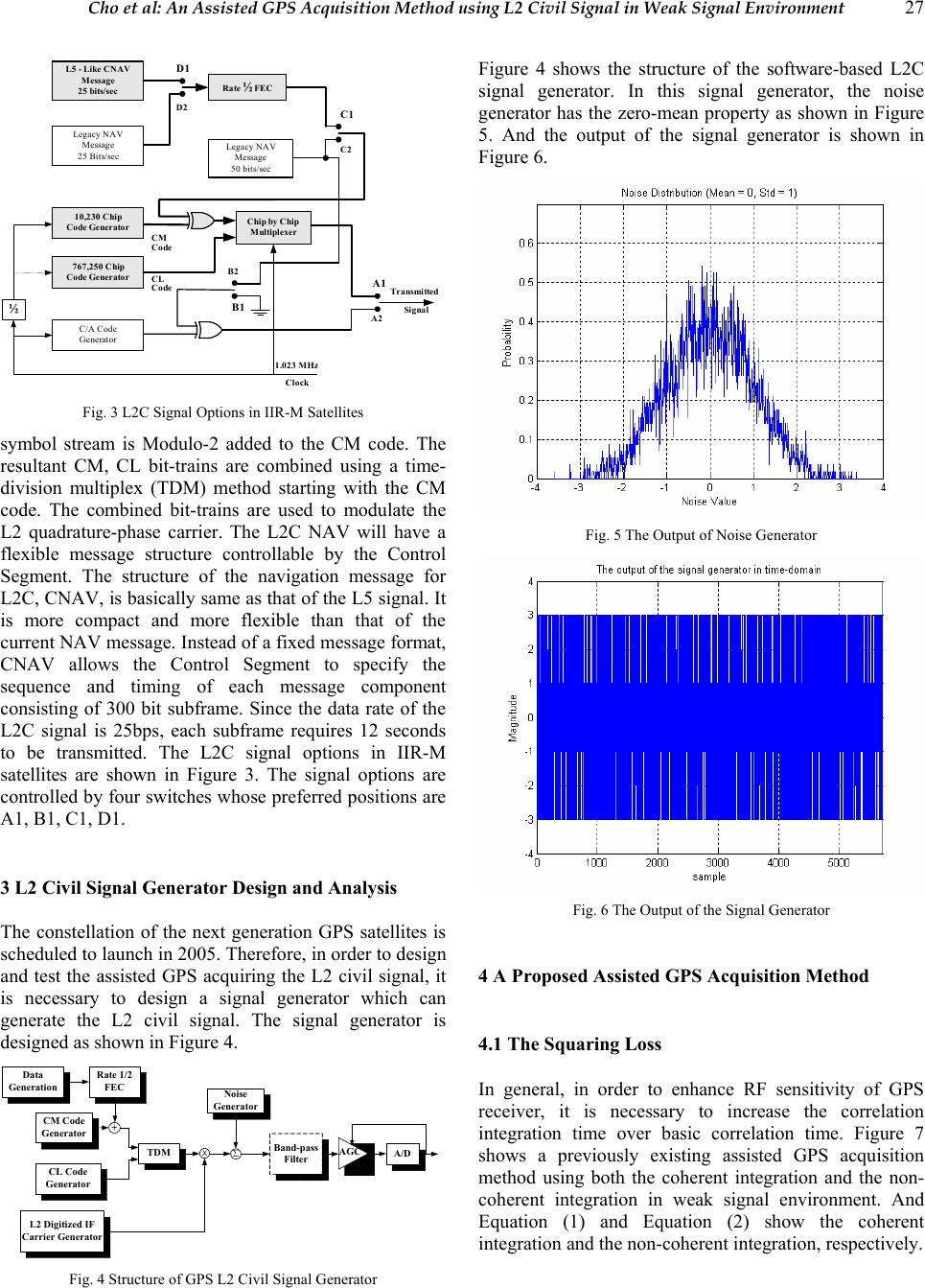 Cho et al: An Assisted GPS Acquisition Method using L2 Civil Signal in Weak Signal Environment 27 L5 - Like CNAV Message 25 bits/secRate ½ FEC Legacy NAV Message 25 Bits/sec 10,230 Chip Code Generator 767,250 Chip Code Generator C/A Code Generator Legacy NAV Message 50 bits/sec Chip by Chip Multiplexer ½ D1 D2 C1 C2 CM Code CL Code B1 B2 A1 A2 Transmitted Signal 1.023 MHz Clock Fig. 3 L2C Signal Options in IIR-M Satellites symbol stream is Modulo-2 added to the CM code. The resultant CM, CL bit-trains are combined using a time- division multiplex (TDM) method starting with the CM code. The combined bit-trains are used to modulate the L2 quadrature-phase carrier. The L2C NAV will have a flexible message structure controllable by the Control Segment. The structure of the navigation message for L2C, CNAV, is basically same as that of the L5 signal. It is more compact and more flexible than that of the current NAV message. Instead of a fixed message format, CNAV allows the Control Segment to specify the sequence and timing of each message component consisting of 300 bit subframe. Since the data rate of the L2C signal is 25bps, each subframe requires 12 seconds to be transmitted. The L2C signal options in IIR-M satellites are shown in Figure 3. The signal options are controlled by four switches whose preferred positions are A1, B1, C1, D1. 3 L2 Civil Signal Generator Design and Analysis The constellation of the next generation GPS satellites is scheduled to launch in 2005. Therefore, in order to design and test the assisted GPS acquiring the L2 civil signal, it is necessary to design a signal generator which can generate the L2 civil signal. The signal generator is designed as shown in Figure 4. CM Code Generator CL Code Generator TDM ∑ L2 Digitized IF Carrier Generator Noise Generator Rate 1/2 FEC Data Generation + XBand-pass Filter AGC A/D Fig. 4 Structure of GPS L2 Civil Signal Generator Figure 4 shows the structure of the software-based L2C signal generator. In this signal generator, the noise generator has the zero-mean property as shown in Figure 5. And the output of the signal generator is shown in Figure 6. Fig. 5 The Output of Noise Generator Fig. 6 The Output of the Signal Generator 4 A Proposed Assisted GPS Acquisition Method 4.1 The Squaring Loss In general, in order to enhance RF sensitivity of GPS receiver, it is necessary to increase the correlation integration time over basic correlation time. Figure 7 shows a previously existing assisted GPS acquisition method using both the coherent integration and the non- coherent integration in weak signal environment. And Equation (1) and Equation (2) show the coherent integration and the non-coherent integration, respectively.  28 Journal of Global Positioning Systems Lowpass Filter∑ = e M k k e Z M1 1∑ = e N k k e Y N1 1 ZY (generated signal) η ≥y y η : detection threshold yes no signal present signal absent (despreading mixer) coherent/non-coherent integration )( k tx 0 T r ω (received signal) τ ω e ) ˆ exp() ˆ (2)( 0krkk tjTCtG ω −⋅= Fig. 7 The Previously Existing Signal Acquisition Method in Assisted GPS After low pass filtering, the output of the coherent integration and the non-coherent integration are ∑ = =e M k k e Z M Y 1 1 (1) () () ∑ = += e N k q k i k e YY N y 1 22 1 (2) where e M and e N are the number of the coherent integration and the non-coherent integration, respectively, k Z is the output of the lowpass filter, Y and y are the output of the coherent integration and the non-coherent integration, respectively. Here Y is composed of the in- phase component, i k Y and the quadrature-component, q k Y. The coherent integration is a technique integrating in- phase correlation result e M times as given by Eq. (1). Therefore, it is assumed that there is no sign inversion of correlation by the navigation message bit transition or assistance of sign inversion information during the coherent integration. A relation of the number e M of the coherent integration and an allowable carrier frequency error e f is given by () ie ie Acq Tf Tf L π π sin log20 10 max = (3) where peiTMT ⋅= is the coherent integration time, p T is the period of integration, and Acq L is the acquisition loss. Eq. (3) shows that the longer integration time requires the less allowable carrier frequency error for the same signal acquisition loss. Since there is no navigation bit stream during the initial acquisition time, the coherent integration technique is not proper to be adopted in the signal acquisition process of generic GPS receivers. For this reason, the generic GPS receiver performs the coherent integration with demodulating the navigation bit stream after the signal acquisition. Here the purpose of the coherent integration is to enhance the Signal-to-Noise (SNR) and to improve the quality of measurements. The non-coherent integration is a technique integrating both the in-phase correlation result and the quadrature- phase correlation result as shown in Eq. (2). Therefore it is not necessary to know the navigation message bit transition. That is, the non-coherent integration is not influenced by sign inversion of the navigation message bit during the integration, and an allowable carrier frequency error is related not to the number of the non- coherent integration but to integration time of correlation values i k Y and q k Y. Therefore the non-coherent integration technique is adopted to enhance RF sensitivity of GPS receiver. But there is a disadvantage that the non- coherent integration induces the squaring loss for weak GPS signals. Particularly the squaring loss is the dominant factor among the acquisition losses of assisted GPS dealing with weak GPS signals. The squaring loss is defined as the ratio of the SNR before the non-coherent integration for the SNR after the non-coherent integration. nc c sq L α α = (4) n s epcc P MTf σ α 2 2= ( ) π π α α − − − − +Γ =4 2 ;1; 2 1 F1 2 1 2 2 11c nc where ( ) ⋅ Γ is the gamma function, ( ) ⋅ 11F is the confluent hypergeometric function, c α is the SNR before the non-coherent integration, and nc α is the SNR after the non-coherent integration. Therefore, the squaring loss is given by − −− +Γ − = π α πα 2 ;1; 2 1 F1 2 1 2 4 2 11 c c sq L (5) And the squaring loss has properties as follows: 1,0 10 =< = c sqsq c LL d d α α (6)  Cho et al: An Assisted GPS Acquisition Method using L2 Civil Signal in Weak Signal Environment 29 From Eq. (6), it is explained that Eq. (5) is a monotonic decreasing function and the non-coherent integration induces the squaring loss when the Signal-to-Noise Ratio (SNR) is below 2/1 10 . As shown in Figure 8, if the SNR before the non-coherent integration is below 2/1 10 , the squaring loss exists. But if the SNR before the non- coherent integration is above 2/1 10 , the squaring loss does not exist. 11.2 1.4 1.6 1.822.2 2.4 2.6 2.8 3 0.8 1 1.2 1.4 1.6 1.8 2 2.2 2.4 αc (SNR before non-coherent integration) [ratio] Lsq Squaring loss Fig. 8 The Squaring Loss vs. the SNR before Non-coherent Integration 4.2 The Proposed Assisted GPS Acquisition Method The signal acquisition method proposed in this paper is shown in Figure 9. It integrates the inner products of adjacent two pair of in-phase components and quadrature- phase components sampled at different time instants as given by Eq. (7) (Lee et al., 2003). kkkkk QQIIY11 −−+= (7) <−− ≥ = ∑ ∑ = = p p N k kk N k kk YY YY y 1 1 0, 0, where p N is the number of the modified non-coherent integration. When only the noise exists, the modified non-coherent integration method results in ( ) ( ) ( )() kqkqkikikn tntntntnty 11 )( −− += (8) 0))(( = kn tyE (9) 2 ))(var( σ = kn ty (10) The squaring loss does not occur because the inner product of adjacent samples has the zero-mean property as given by Eq. (9). 5 Performance Evaluation Test To compare the signal acquisition performance of the proposed assisted GPS acquisition method using L2CS with that of the existing assisted GPS method using L1 signals in the same environment, this paper performed the signal acquisition test using signal generator designed in section 3. First of all, this paper evaluates the GPS L1 signal acquisition performance using the previously existing acquisition method of Figure 7 and then evaluates the L1 and L2 civil signal acquisition performance using the proposed acquisition method. It is assumed that the existing acquisition method of Figure 7 uses the navigation message bit information, and performs the 50 times non-coherent integration after ∑ = p N i i p Y N1 1 Y η ≥ y y η : detection threshold yes no signal presentsignal absent Proposed Acquisition Scheme ∑ = p M i i p Z M1 1 delay ppTM Y ~ ∗ ( ) [ ] YSqr ~ Re Y Lowpass Filter Z (generated signal) (despreading mixer) )( k tx 0 T r ω (received signal) τ ω e ) ˆ exp() ˆ (2)(0krkktjTCtG ω −⋅= Fig. 9 The Proposed Signal Acquisition Method in Assisted GPS 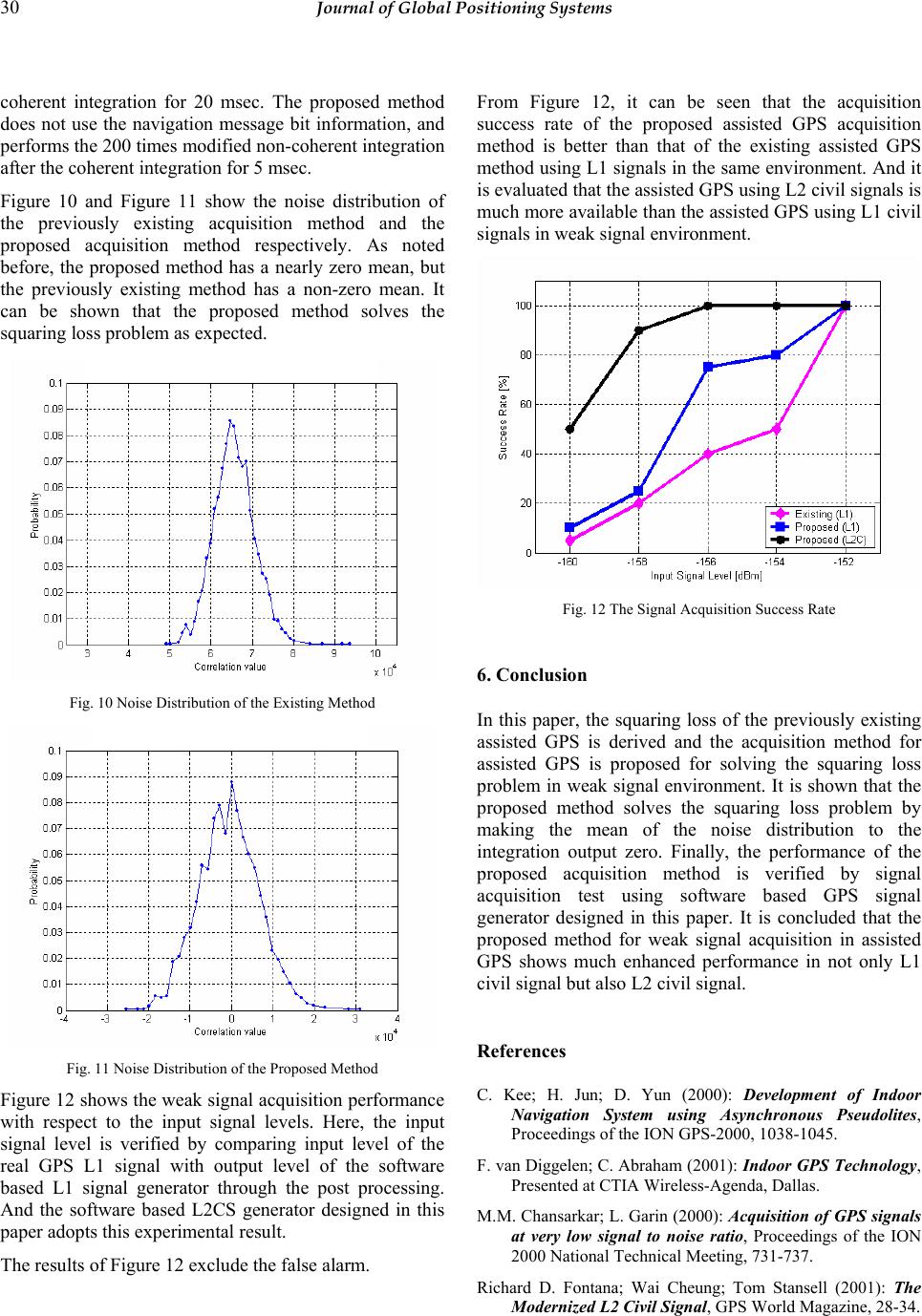 30 Journal of Global Positioning Systems coherent integration for 20 msec. The proposed method does not use the navigation message bit information, and performs the 200 times modified non-coherent integration after the coherent integration for 5 msec. Figure 10 and Figure 11 show the noise distribution of the previously existing acquisition method and the proposed acquisition method respectively. As noted before, the proposed method has a nearly zero mean, but the previously existing method has a non-zero mean. It can be shown that the proposed method solves the squaring loss problem as expected. Fig. 10 Noise Distribution of the Existing Method Fig. 11 Noise Distribution of the Proposed Method Figure 12 shows the weak signal acquisition performance with respect to the input signal levels. Here, the input signal level is verified by comparing input level of the real GPS L1 signal with output level of the software based L1 signal generator through the post processing. And the software based L2CS generator designed in this paper adopts this experimental result. The results of Figure 12 exclude the false alarm. From Figure 12, it can be seen that the acquisition success rate of the proposed assisted GPS acquisition method is better than that of the existing assisted GPS method using L1 signals in the same environment. And it is evaluated that the assisted GPS using L2 civil signals is much more available than the assisted GPS using L1 civil signals in weak signal environment. Fig. 12 The Signal Acquisition Success Rate 6. Conclusion In this paper, the squaring loss of the previously existing assisted GPS is derived and the acquisition method for assisted GPS is proposed for solving the squaring loss problem in weak signal environment. It is shown that the proposed method solves the squaring loss problem by making the mean of the noise distribution to the integration output zero. Finally, the performance of the proposed acquisition method is verified by signal acquisition test using software based GPS signal generator designed in this paper. It is concluded that the proposed method for weak signal acquisition in assisted GPS shows much enhanced performance in not only L1 civil signal but also L2 civil signal. References C. Kee; H. Jun; D. Yun (2000): Development of Indoor Navigation System using Asynchronous Pseudolites, Proceedings of the ION GPS-2000, 1038-1045. F. van Diggelen; C. Abraham (2001): Indoor GPS Technology, Presented at CTIA Wireless-Agenda, Dallas. M.M. Chansarkar; L. Garin (2000): Acquisition of GPS signals at very low signal to noise ratio, Proceedings of the ION 2000 National Technical Meeting, 731-737. Richard D. Fontana; Wai Cheung; Tom Stansell (2001): The Modernized L2 Civil Signal, GPS World Magazine, 28-34.  Cho et al: An Assisted GPS Acquisition Method using L2 Civil Signal in Weak Signal Environment 31 Richard D. Fontana; Wai Cheung; Paul M. Novak; Tom Stansell (2001): The New L2 Civil Signal, Proceedings of the ION 2001 International Technical Meeting, 617-631. Sang Jeong Lee; Deuk Jae Cho; Sang Hyun Park (2003): A Digital Correlator Design for Assisted GPS, Proceedings of the International Symposium on Information Science and Electrical Engineering 2003 (ISEE 2003), ACROS Fukuoka, Japan, 275-278. S.G. Glisic, et al. (1999): New PN code acquisition scheme for CDMA network with low signal-to-noise ratios, IEEE Transactions on communications, Vol. 47, No. 2. S. Soliman; S. Glazko; P. Agashe (1999): GPS receiver sensitivity enhancement in wireless applications, Proceedings of 1999 IEEE MTT-S Symposium, 181-186. T. Haddrell; A. R. Pratt (2001): Understanding the indoor GPS signal, Proceedings of the ION 2001 International Technical Meeting, 1487-1499. T. Hartman; L. Boyd; D. Koster; J. Rajan; J. Harvey (2000): Modernizing the GPS Block IIR Spacecraft, Proceedings of the ION GPS-2000, 2115-2121. W. Marquis (2001): M is for Modernization: Block IIR-M Satellites Improve on a classic, GPS World Magazine, 38- 44. |