Paper Menu >>
Journal Menu >>
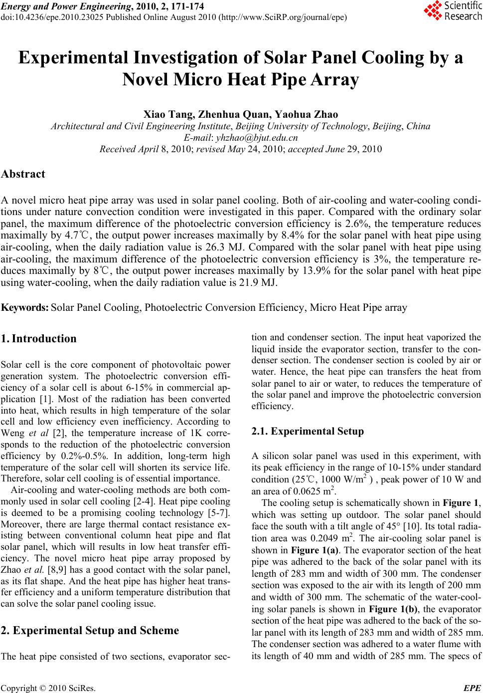 Energy and Power Engineering, 2010, 2, 171-174 doi:10.4236/epe.2010.23025 Published Online August 2010 (http://www.SciRP.org/journal/epe) Copyright © 2010 SciRes. EPE Experimental Investigation of Solar Panel Cooling by a Novel Micro Heat Pipe Array Xiao Tang, Zhenhua Quan, Yaohua Zhao Architectural and Civil Engineering Institute, Beijing University of Technology, Beijing, China E-mail: yhzhao@bjut.edu.cn Received April 8, 2010; revised May 24, 2010; accepted June 29, 2010 Abstract A novel micro heat pipe array was used in solar panel cooling. Both of air-cooling and water-cooling condi- tions under nature convection condition were investigated in this paper. Compared with the ordinary solar panel, the maximum difference of the photoelectric conversion efficiency is 2.6%, the temperature reduces maximally by 4.7, the ou℃tput power increases maximally by 8.4% for the solar panel with heat pipe using air-cooling, when the daily radiation value is 26.3 MJ. Compared with the solar panel with heat pipe using air-cooling, the maximum difference of the photoelectric conversion efficiency is 3%, the temperature re- duces maximally by 8, the output power increases maximally by 13.9%℃ for the solar panel with heat pipe using water-cooling, when the daily radiation value is 21.9 MJ. Keywords: Solar Panel Cooling, Photoelectric Conversion Efficiency, Micro Heat Pipe array 1. Introduction Solar cell is the core component of photovoltaic power generation system. The photoelectric conversion effi- ciency of a solar cell is about 6-15% in commercial ap- plication [1]. Most of the radiation has been converted into heat, which results in high temperature of the solar cell and low efficiency even inefficiency. According to Weng et al [2], the temperature increase of 1K corre- sponds to the reduction of the photoelectric conversion efficiency by 0.2%-0.5%. In addition, long-term high temperature of the solar cell will shorten its service life. Therefore, solar cell cooling is of essential importance. Air-cooling and water-cooling methods are both com- monly used in solar cell cooling [2-4]. Heat pipe cooling is deemed to be a promising cooling technology [5-7]. Moreover, there are large thermal contact resistance ex- isting between conventional column heat pipe and flat solar panel, which will results in low heat transfer effi- ciency. The novel micro heat pipe array proposed by Zhao et al. [8,9] has a good contact with the solar panel, as its flat shape. And the heat pipe has higher heat trans- fer efficiency and a uniform temperature distribution that can solve the solar panel cooling issue. 2. Experimental Setup and Scheme The heat pipe consisted of two sections, evaporator sec- tion and condenser section. The input heat vaporized the liquid inside the evaporator section, transfer to the con- denser section. The condenser section is cooled by air or water. Hence, the heat pipe can transfers the heat from solar panel to air or water, to reduces the temperature of the solar panel and improve the photoelectric conversion efficiency. 2.1. Experimental Setup A silicon solar panel was used in this experiment, with its peak efficiency in the range of 10-15% under standard condition (25℃, 1000 W/m2 ) , peak power of 10 W and an area of 0.0625 m2. The cooling setup is schematically shown in Figure 1, which was setting up outdoor. The solar panel should face the south with a tilt angle of 45° [10]. Its total radia- tion area was 0.2049 m2. The air-cooling solar panel is shown in Figure 1(a). The evaporator section of the heat pipe was adhered to the back of the solar panel with its length of 283 mm and width of 300 mm. The condenser section was exposed to the air with its length of 200 mm and width of 300 mm. The schematic of the water-cool- ing solar panels is shown in Figure 1(b), the evaporator section of the heat pipe was adhered to the back of the so- lar panel with its length of 283 mm and width of 285 mm. The condenser section was adhered to a water flume with its length of 40 mm and width of 285 mm. The specs of 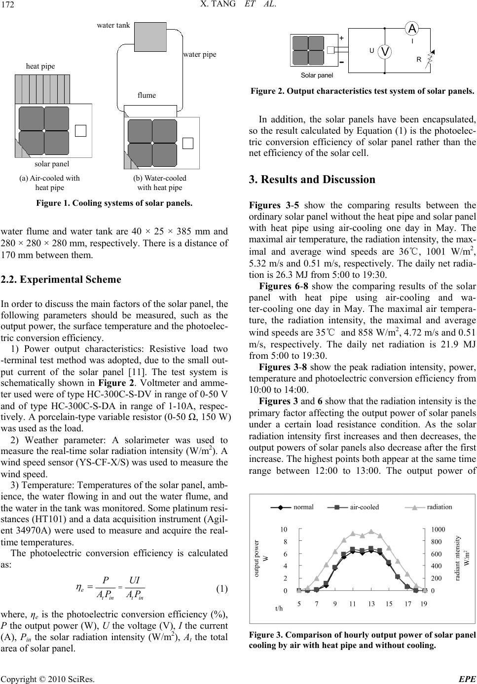 X. TANG ET AL. Copyright © 2010 SciRes. EPE 172 heat pipe solar panel water tank water pip e flume (a) Air-cooled with heat pipe (b) Water-cooled with heat pipe Figure 1. Cooling systems of solar panels. water flume and water tank are 40 × 25 × 385 mm and 280 × 280 × 280 mm, respectively. There is a distance of 170 mm between them. 2.2. Experimental Scheme In order to discuss the main factors of the solar panel, the following parameters should be measured, such as the output power, the surface temperature and the photoelec- tric conversion efficiency. 1) Power output characteristics: Resistive load two -terminal test method was adopted, due to the small out- put current of the solar panel [11]. The test system is schematically shown in Figure 2. Voltmeter and amme- ter used were of type HC-300C-S-DV in range of 0-50 V and of type HC-300C-S-DA in range of 1-10A, respec- tively. A porcelain-type variable resistor (0-50 Ω, 150 W) was used as the load. 2) Weather parameter: A solarimeter was used to measure the real-time solar radiation intensity (W/m2). A wind speed sensor (YS-CF-X/S) was used to measure the wind speed. 3) Temperature: Temperatures of the solar panel, amb- ience, the water flowing in and out the water flume, and the water in the tank was monitored. Some platinum resi- stances (HT101) and a data acquisition instrument (Agil- ent 34970A) were used to measure and acquire the real- time temperatures. The photoelectric conversion efficiency is calculated as: e tin tin PUI A PAP (1) where, ηe is the photoelectric conversion efficiency (%), P the output power (W), U the voltage (V), I the current (A), Pin the solar radiation intensity (W/m2), At the total area of solar panel. R V A Solar panel U I + - Figure 2. Output characteristics test system of solar panels. In addition, the solar panels have been encapsulated, so the result calculated by Equation (1) is the photoelec- tric conversion efficiency of solar panel rather than the net efficiency of the solar cell. 3. Results and Discussion Figures 3-5 show the comparing results between the ordinary solar panel without the heat pipe and solar panel with heat pipe using air-cooling one day in May. The maximal air temperature, the radiation intensity, the max- imal and average wind speeds are 36℃, 1001 W/m2, 5.32 m/s and 0.51 m/s, respectively. The daily net radia- tion is 26.3 MJ from 5:00 to 19:30. Figures 6-8 show the comparing results of the solar panel with heat pipe using air-cooling and wa- ter-cooling one day in May. The maximal air tempera- ture, the radiation intensity, the maximal and average wind speeds are 35℃ and 858 W/m2, 4.72 m/s and 0.51 m/s, respectively. The daily net radiation is 21.9 MJ from 5:00 to 19:30. Figures 3-8 show the peak radiation intensity, power, temperature and photoelectric conversion efficiency from 10:00 to 14:00. Figures 3 and 6 show that the radiation intensity is the primary factor affecting the output power of solar panels under a certain load resistance condition. As the solar radiation intensity first increases and then decreases, the output powers of solar panels also decrease after the first increase. The highest points both appear at the same time range between 12:00 to 13:00. The output power of Figure 3. Comparison of hourly output power of solar panel cooling by air with heat pipe and without cooling. 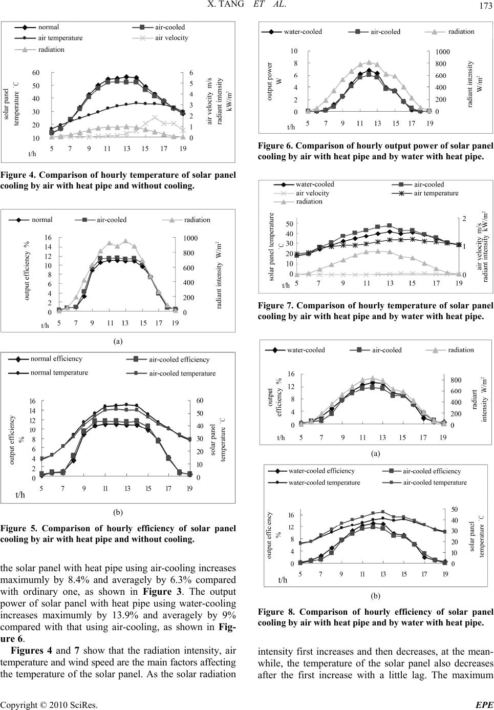 X. TANG ET AL. Copyright © 2010 SciRes. EPE 173 Figure 4. Comparison of hourly temperature of solar panel cooling by air with heat pipe and without cooling. (a) (b) Figure 5. Comparison of hourly efficiency of solar panel cooling by air with heat pipe and without cooling. the solar panel with heat pipe using air-cooling increases maximumly by 8.4% and averagely by 6.3% compared with ordinary one, as shown in Figure 3. The output power of solar panel with heat pipe using water-cooling increases maximumly by 13.9% and averagely by 9% compared with that using air-cooling, as shown in Fig- ure 6. Figures 4 and 7 show that the radiation intensity, air temperature and wind speed are the main factors affecting the temperature of the solar panel. As the solar radiation Figure 6. Comparison of hourly output power of solar panel cooling by air with heat pipe and by water with heat pipe. Figure 7. Comparison of hourly temperature of solar panel cooling by air with heat pipe and by water with heat pipe. (a) (b) Figure 8. Comparison of hourly efficiency of solar panel cooling by air with heat pipe and by water with heat pipe. intensity first increases and then decreases, at the mean- while, the temperature of the solar panel also decreases after the first increase with a little lag. The maximum 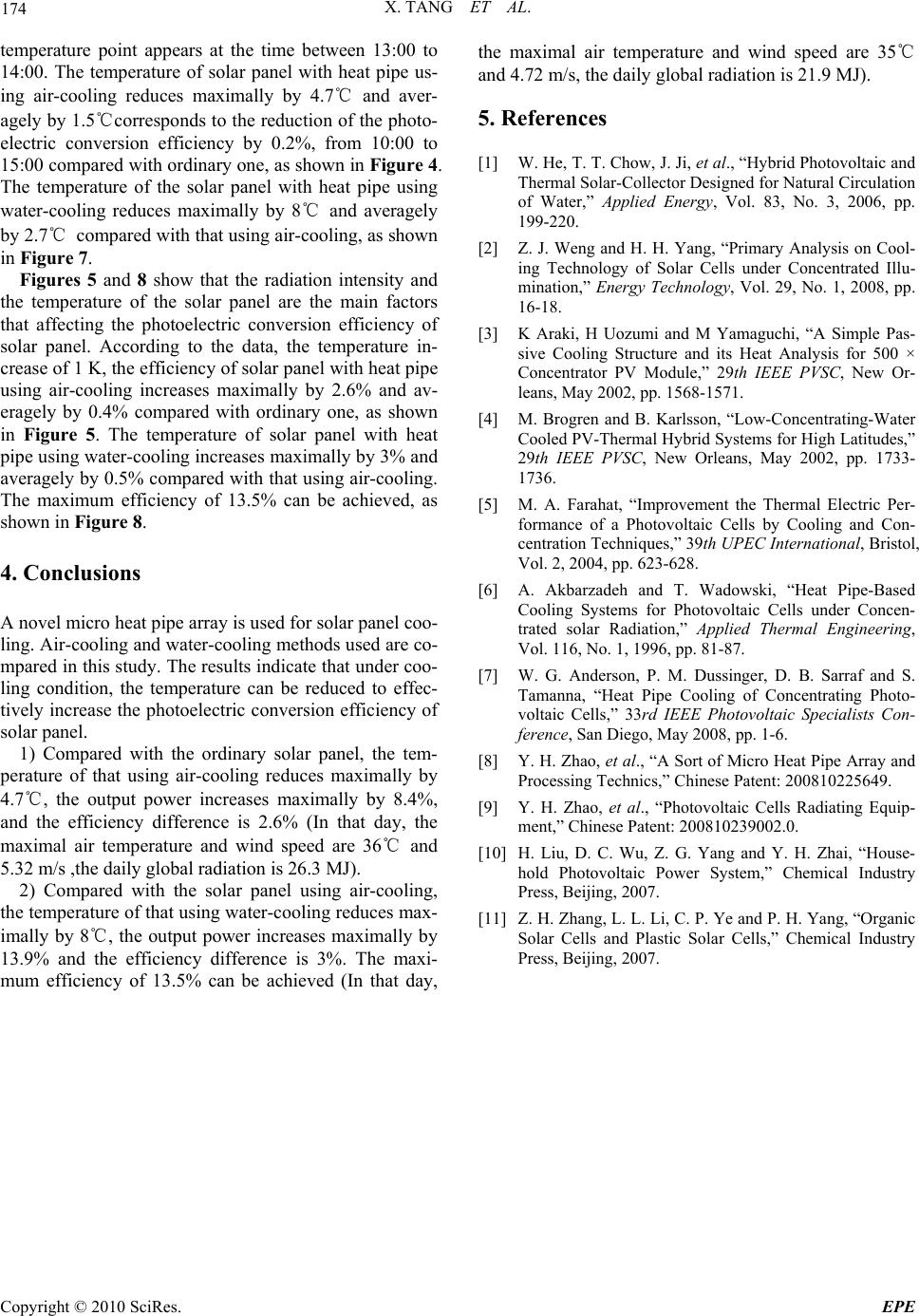 X. TANG ET AL. Copyright © 2010 SciRes. EPE 174 temperature point appears at the time between 13:00 to 14:00. The temperature of solar panel with heat pipe us- ing air-cooling reduces maximally by 4.7℃ and aver- agely by 1.5℃corresponds to the reduction of the photo- electric conversion efficiency by 0.2%, from 10:00 to 15:00 compared with ordinary one, as shown in Figure 4. The temperature of the solar panel with heat pipe using water-cooling reduces maximally by 8℃ and averagely by 2.7℃ compared with that using air-cooling, as shown in Figure 7. Figures 5 and 8 show that the radiation intensity and the temperature of the solar panel are the main factors that affecting the photoelectric conversion efficiency of solar panel. According to the data, the temperature in- crease of 1 K, the efficiency of solar panel with heat pipe using air-cooling increases maximally by 2.6% and av- eragely by 0.4% compared with ordinary one, as shown in Figure 5. The temperature of solar panel with heat pipe using water-cooling increases maximally by 3% and averagely by 0.5% compared with that using air-cooling. The maximum efficiency of 13.5% can be achieved, as shown in Figure 8. 4. Conclusions A novel micro heat pipe array is used for solar panel coo- ling. Air-cooling and water-cooling methods used are co- mpared in this study. The results indicate that under coo- ling condition, the temperature can be reduced to effec- tively increase the photoelectric conversion efficiency of solar panel. 1) Compared with the ordinary solar panel, the tem- perature of that using air-cooling reduces maximally by 4.7℃, the output power increases maximally by 8.4%, and the efficiency difference is 2.6% (In that day, the maximal air temperature and wind speed are 36℃ and 5.32 m/s ,the daily global radiation is 26.3 MJ). 2) Compared with the solar panel using air-cooling, the temperature of that using water-cooling reduces max- imally by 8℃, the output power increases maximally by 13.9% and the efficiency difference is 3%. The maxi- mum efficiency of 13.5% can be achieved (In that day, the maximal air temperature and wind speed are 35℃ and 4.72 m/s, the daily global radiation is 21.9 MJ). 5. References [1] W. He, T. T. Chow, J. Ji, et al., “Hybrid Photovoltaic and Thermal Solar-Collector Designed for Natural Circulation of Water,” Applied Energy, Vol. 83, No. 3, 2006, pp. 199-220. [2] Z. J. Weng and H. H. Yang, “Primary Analysis on Cool- ing Technology of Solar Cells under Concentrated Illu- mination,” Energy Technology, Vol. 29, No. 1, 2008, pp. 16-18. [3] K Araki, H Uozumi and M Yamaguchi, “A Simple Pas- sive Cooling Structure and its Heat Analysis for 500 × Concentrator PV Module,” 29th IEEE PVSC, New Or- leans, May 2002, pp. 1568-1571. [4] M. Brogren and B. Karlsson, “Low-Concentrating-Water Cooled PV-Thermal Hybrid Systems for High Latitudes,” 29th IEEE PVSC, New Orleans, May 2002, pp. 1733- 1736. [5] M. A. Farahat, “Improvement the Thermal Electric Per- formance of a Photovoltaic Cells by Cooling and Con- centration Techniques,” 39th UPEC International, Bristol, Vol. 2, 2004, pp. 623-628. [6] A. Akbarzadeh and T. Wadowski, “Heat Pipe-Based Cooling Systems for Photovoltaic Cells under Concen- trated solar Radiation,” Applied Thermal Engineering, Vol. 116, No. 1, 1996, pp. 81-87. [7] W. G. Anderson, P. M. Dussinger, D. B. Sarraf and S. Tamanna, “Heat Pipe Cooling of Concentrating Photo- voltaic Cells,” 33rd IEEE Photovoltaic Specialists Con- ference, San Diego, May 2008, pp. 1-6. [8] Y. H. Zhao, et al., “A Sort of Micro Heat Pipe Array and Processing Technics,” Chinese Patent: 200810225649. [9] Y. H. Zhao, et al., “Photovoltaic Cells Radiating Equip- ment,” Chinese Patent: 200810239002.0. [10] H. Liu, D. C. Wu, Z. G. Yang and Y. H. Zhai, “House- hold Photovoltaic Power System,” Chemical Industry Press, Beijing, 2007. [11] Z. H. Zhang, L. L. Li, C. P. Ye and P. H. Yang, “Organic Solar Cells and Plastic Solar Cells,” Chemical Industry Press, Beijing, 2007. |