 American Journal of Industrial and Business Management, 2012, 2, 116-127 http://dx.doi.org/10.4236/ajibm.2012.24016 Published Online October 2012 (http://www.SciRP.org/journal/ajibm) Configuration Model for Automating Work System Design Muhamad Arfauz A. Rahman1, John P. T. Mo2 1Faculty of Manufacturing Engineering, Universiti Teknikal Malaysia Melaka, Hang Tuah Jaya, Malaysia; 2School of Aerospace Mechanical and Manufacturing Engineering, Bundoora, Australia. Email: arfauz@utem.edu.my Received May 5th, 2012; revised June 4th, 2012; accepted July 2nd, 2012 ABSTRACT The design of an automation work system involves important choices concerning the type of system process as well as the condition of the process. These are based on the requirements from the user. This work provides the development of configuration model for automating the design of work system. The model consists of the extraction and execution process of user requirements. It begins with the identification of the requirement statement. Once identified, the state- ment is extracted and sorted accordingly into process type, number of item count and condition of the process. Cur- rently, the model considers simple sorting and basic assembly process. The model continues to the selection of system action and system component. At the end of the work, the user requirements are transformed into a set of system model and eventually provide the desired system specification. At this stage, the model is represented in a symbolic flow process. Keywords: Automation; Configuration; System Actions; System Components; User Requirements; Work System 1. Introduction In configuring the automation work system, Mo et al. [1] believe that the goal is not about adapting one system to another, but rather to develop an automation work system from a task description independent of the other system, and subsequently assign components to achieve the specified function. Configuration of manufacturing sys- tems is a strategic decision. However, many companies have lost their production capabilities every time they acquire a new system or modifying existing system. Re- gardless of the cause, companies have a challenging problem arise due to selecting new resources that fit their future needs better [2,3]. This phase is a very critical since each decision taken will directly affect the per- formance of the new system at this level and therefore its profitability in the future. Often, the information avail- able at the early configuration stage is not detailed and is sometimes uncertain. According to Matta et al. [4] this is true especially when uncertainty of the market demand need to be considered during the configuration of the system. This is important since unexpected variations of the volumes required by the market, or the introduction of new products, can make the solution unsuitable to fulfill the market requests. At the same time, the decision must consider many system variables such as the process type, number of iteration and the process condition. To solve the problem, a simplified methodology that can deal with all the aspects described above is necessary. 2. Configuration Phase To understand the configuration process, phases involve in the designing of work system must be understood and followed. The following Figure 1 shows the configura- tion and reconfiguration phases of work system. The success of any automation work system configu- ration and reconfiguration will depend upon how well the system is executed at the beginning of the phase. The figure shows the generic configuration process that was concluded based on various methods on configuration and reconfiguration process include Monfared and Wes- ton [5], Stoin and Frumusanu [6], Wiendahl et al. [7], Travaini et al. [8], and ElMaraghy et al. [9]. Variation in customer demands indicates changes in the market. Spe- cific method on the acquisition of the user requirements and later transforming the information into system speci- fications has not been done. In line with the changes, Covanich and McFarlane [10] through their case study believe that an easy and simple engine is required to ma- nipulate the requirement from the customers. Changes in market indicate changes in user requirements. Ferscha et al. [11] have agreed that a low flexibility of the system is amongst the challenges that limit the system’s capability to adapt with new requirement. Therefore, new systems need to be set up. However setting up a new system is very costly. Often reconfigurable manufacturing system (RMS) the current system is manipulated to suit with the new requirement. Copyright © 2012 SciRes. AJIBM  Configuration Model for Automating Work System Design 117 Figure 1. Work system configuration phases. An appropriate system specification is an essential step leading to the successful implementation of automation work system configuration. Toni and Tonchia [12] had earlier discovered that the system needs to be configured and reconfigured accordingly from time to time in order to adapt with the new user requirements. In specifying system specifications, few components need to be visualized. These include action of each proc- ess known as system actions as well as the corresponding components known as system component provided by Rahman and Mo [13]. Once the specification has been produced, the next process involves implementing the system in term of hardware. The implementation stage often requires manual step. At this stage, the research requires diverse concept not limited to initial configura- tion of a new automation work system but also to recon- figure the existing system. According to Mo et al. [1], in building an automation system, components required may be associated through physical or non physical specifications at different types. Due to various changing needs, addition or removal of physical components in the system will be severely affected, thus affecting the finan- cial component as well. The first step to configure the system is to design the system accordingly. The next process involves the integration of the hard- ware system with any software component. Various method for integrating the component have been intro- duced including through combined ontological represen- tation of the low-level functionality at the high-level control layer by Lepuschitz et al. [14] and through Re- configurable Manufacturing Execution Systems Archi- tecture (RMESA) by Huang et al. [15]. This includes programmable logic controller or micro controller. The final stage of the phase will be the execution part. Currently, the acquisition process shown in Figure 1 is conducted manually in which a group of system design engineer organized many discussions and meetings to understand the user requirements and specifications. However there is no effort to tackle the capturing of the requirements and transforming it into the system specifi- cations using the mention method. This is essential be- cause the system specification is scenario dependent in which the requirements will provide more precise infor- mation towards reconfiguration. Hence, without properly capture the requirements; the system may have not been designed correctly. It is obvious from the reviews that various methods on configuration and reconfiguration were created but there were no specific research con- ducted on capturing the requirements. Capturing the re- quirements or user requirements is essential steps to sim- plify the configuration and reconfiguration works as shown in Figure 1. To act as fast as possible, a specific automated method to capture and manipulate the user requirements and later provide an optimum solution for the design of flexible and reconfigurable manufacturing automation system is essential to complement with the current effort. It is noted that the outcome of this work will undoubtedly provide highly flexible and easily platform to adapt with various manufacturing conditions with also less human involvement. This platform will not only cater for initial system design and development but also for system re- configuration as well. Copyright © 2012 SciRes. AJIBM  Configuration Model for Automating Work System Design 118 3. Focus Development In this work, the focus is on developing item in phase 1 and 2 of Figure 1. In order to come up with a suitable method, a specific model for extraction and configuration needs to be introduced. The actual theory of the model is briefly explained in this section. The initial work need to be initiated. The idea is to introduce the extraction proc- ess. The detail activity for this work is shown in the fol- lowing Figure 2. In Figure 2, the configuration process starts after the requirements are received from the customer, i.e. from the market. The process then continues analyzing the requirements and extracts the key elements from the in- put information. The outcomes of the requirements are passed to the configuration module which produces the proposed configuration for implementation. 3.1. Requirements The critical task in the automated configuration system is recognition of user requirements. Most of the require- ment information comes directly from the customer but there are other channels such as media and market intel- ligence sources that can be consolidated into some de- scription for the system designer. In reality, these re- quirements are expressed in documents which are vague and often misleading. Therefore, many engineering de- sign teams use the concept of quality function deploy- ment (QFD) [16]. Jiang et al. [17] presented an overall review of QFD in the past 30 years. They adopted the “action research” approach interacting with product de- velopment groups and organisation, and proposed a model with 17 subsystems that linked system and prod- uct design to quality. Ocak [18] studied 2 competing companies using QFD method to provide a comprehen- sive, systematic approach to ensure customer require- ments and expectations are met via applying improve- ments to design, production and management phases in manufacturing system design. The results of the QFD study could assist the companies to focus on specific issues. Traditionally, QFD is used to capture the voice of the customer (i.e. requirements) and translates it into techni- cal design requirements [19]. According to Mehrjerdi [20], the source of information for determining require- ments come marketing surveys and case studies. More importantly, the requirements of the so-called unspoken customers could be captured by the “house of quality” (HoQ) [21]. The concept of HoQ originated from Toyota Motor Corporation [22]. The tool is composed of a set of matrices that represents the relationships between cus- tomer requirements (CRs) and technical characteristics (TCs). Once these relationships are quantified, a combi- nation of different analysis and decision methods can be used to determine the outcome. However, the QFD concept and HoQ methodologies have some drawbacks [23]. An inconsistent HoQ chart is one in which the information from the roof matrix is in- consistent with that from the relationship matrix. It is necessary to establish processes through which the con- sistency of information collected in HoQ and QFD is checked [24]. The system reconfiguration projects that this paper investigates certainly need information from the user to determine the best option for the manufacturing tasks. Capturing user requirements in the least restriction manner is essential to facilitate accuracy through the de- scriptions [25]. Hence, this research adopts a linquistic approach to capture user requirements from sentences. Examples of user requirements are illustrated in the following sentences: a) Sort 2 materials by weight; b) Assemble 2 parts by inserting B on top of A; c) Paint the 2 surface with 2 different colors; d) Classify object according to 4 different colors; e) 4 items need to be categorized according to height. These requirements contain useful information for Figure 2. Extraction and configuration activity. Copyright © 2012 SciRes. AJIBM  Configuration Model for Automating Work System Design 119 system designer to configure a new system. According to Rahman and Mo [13], a basic user requirement can be divided into three main elements. There are type of process (P), condition (C) and number of iteration (I). According to Ratchev et al. [26], these elements will give basic information required to configure a system and are required to identify the general idea of the system to be designed. A simple method to differentiate between all the elements is described in the next section. 3.2. Extraction Module To configure a system, user requirements need to be clearly identified and simplified. At the beginning of the process, an understandable set of user requirements is required, either from verbal description or by some documentation or statement, to formulate a conceptual model of what the system is supposed to do. The key in this process is the identification of user requirements in sentence and keywords, which have unique meanings. Later, the user requirement will be transformed into sys- tem specifications. These forms are well presented by Manesh [27]. From the examples in previous subsection, it is logical to divide the user requirements into the three elements P, I and C. The following describe examples of characteris- tics of the elements. a) Possible Process Type (P): Sort—1, 2, 3, ···, n product Assemble—1, 2, 3, ···, n part Hence, the main characteristic of P is based on key- words which are contained as verbs. b) Possible Number of Item Count (I): “n” number of product “n” number of part Hence, the main characteristics of I is integer numbers, starting from 1, 2, 3, ···, n. c) Possible Condition (C): By weight, material, height From side, top, bottom Hence, the main characteristic of C is based on key- words, but they are adjective. Now, the extraction process can be defined with the following rules: For P, extract by a database of key verbs. For I, look for numbers. For C, look for adjective etc. in the database. In order for the configuration module to derive the re- sult, the elements P, I and C are required to be extracted from the user requirements. For example, using user re- quirement (a), the extraction logic can be shown in Fig- ure 3. Generalising, we can map any user requirement by the following relation: R P,I,C (1) In our case, R = Sort 2 materials by weight P = Sort I = 2 C = by weight Similarly, analysing user requirement (b) gives the following relation: Sort 2 materials by weight P IC Figure 3. Extraction of user requirements. Figure 4. Generalized transformation system model. Copyright © 2012 SciRes. AJIBM  Configuration Model for Automating Work System Design 120 Figure 5. Sorting actions for two components. Assemble2partsbyinsertingB ontopofA Assemble, 2, by insertingB ontop ofA. (2) 3.3. Configuration Module The generalized transformation of system model of this research part is shown in the following Figure 4. In the figure, the beginning part shows the user re- quirements which can be categorized into three main parts. The figure clearly shows the following user re- quirements, P, I and C. 3.3.1. System Action The first step to introduce a configuration model rose after a series or a combination of system action (SA) is created. In this case, the model can be initially shown in the following sequence: 1234 SA SASASASAn The system action may consist of the following action SET, RESET, RECOGNIZE, MOVE, EJECT, HOLD. Selection and/or combination of the system action is based on the process type acquired from the user re- quirements commencing from 1 until nth number. This nth number indicates the total number of system action re- quired to complete the process. It will depend on the number of item count (I) from the user requirement. The following Figure 5 shows a combination of system ac- tion for sorting process from a study conducted by Rah- man and Mo [13]: The combination shows sorting of 2 component of different weight. In this case n = 2 and the condition, c is weight. Further to the increment of the number of com- ponent to be sorted for n = 3 or more, another similar combination of system action was added as illustrated in Figure 6 for nth. From the combination, it shows a unique pattern that can be used to generalize the system action. Therefore, for “n” number of component to be sorted, n SA 5n14 For sorting case the value of n ≥ 2, otherwise the process will not doing any sorting. In term of the se- quence of the system action, the sorting process chooses alternative combination. The process will choose the system action combination accordingly upon receiving the information at the earlier recognition process at SA2. The process will be decided to proceed with SA4 or SA6 immediately after SA3. Figure 6. Sorting actions for five components. Copyright © 2012 SciRes. AJIBM  Configuration Model for Automating Work System Design 121 Figure 7. Assembly actions for tw o subasse mblie s. Figure 8. Assembly actions for five subasse mblie s. Sep SortBase2 SA SortBase1 Alternative 2SA Sort 3SAor 4SA In order to study the other type of processes, the fol- lowing combination of system action for assembly can also be shown in Figure 7 as follows: The combination shows assembly of two subassem- blies together for n = 2 case. For assembly of three sub- assemblies of n = 3 or more, combination of four system action, will occurs. Finally, Figure 8 shows combination for nth. Again, the combination shows a unique pattern than can be generalized for indicating the total number of system action required for this assembly process: n SA 5n14 The value of n for assembly process is ≥2, otherwise the process will not do assembling task. In term of the sequence of the system action, the assembly process chooses direct combination. The process will add the system action combination accordingly upon receiving the information at the earlier recognition process at SA2. The process will add numbers of subassemblies accord- ingly. Seq AssyBase1AssyBase2 AssySA= 3SAn14SA2SA Each system action will indicate a need for certain type of component. In the next section system component (SC) is introduced to the current combination which will further derive the model. 3.3.2. System Com p onent Given a single combination of system action, each sys- tem action will react and correspond to a specific system component from the system component repository. In this case, the total number of system component is simi- lar to the total number of system action. 123 4 SA SASASAS 1234 SC SCSC SCSC At this stage, list of component are required in order to suit with the desired system component as well as corre- sponding system action. Since the expected outcome of the manufacturing system may differ from one to another, extensive lists are required. A set of components will be created which will store the database and will be known as system component repository. This repository contains numbers of components needed for setting up various types of system. The repository will provide heaps of data regarding various components required in the proc- essing level of the proposed configuration work. The following Table 1 shows an example of the developed Copyright © 2012 SciRes. AJIBM 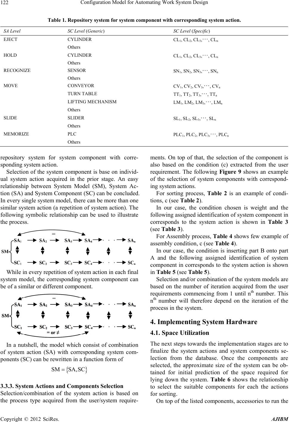 Configuration Model for Automating Work System Design 122 Table 1. Repository system for system component with corresponding system action. SA Level SC Level (Generic) SC Level (Specific) EJECT CYLINDER CL1, CL2, CL3,···, CLn Others HOLD CYLINDER CL1, CL2, CL3,···, CLn Others RECOGNIZE SENSOR SN1, SN2, SN3,···, SNn Others MOVE CONVEYOR CV1, CV2, CV3,···, CVn TURN TABLE TT1, TT2, TT3,···, TTn LIFTING MECHANISM LM1, LM2, LM3,···, LMn Others SLIDE SLIDER SL1, SL2, SL3,···, SLn Others MEMORIZE PLC PLC1, PLC2, PLC3,···, PLCn Others repository system for system component with corre- sponding system action. Selection of the system component is base on individ- ual system action acquired in the prior stage. An easy relationship between System Model (SM), System Ac- tion (SA) and System Component (SC) can be concluded. In every single system model, there can be more than one similar system action (a repetition of system action). The following symbolic relationship can be used to illustrate the process. While in every repetition of system action in each final system model, the corresponding system component can be of a similar or different component. In a nutshell, the model which consist of combination of system action (SA) with corresponding system com- ponents (SC) can be rewritten in a function form of SM SA,SC 3.3.3. S y stem Actions and Component s S election Selection/combination of the system action is based on the process type acquired from the user/system require- ments. On top of that, the selection of the component is also based on the condition (c) extracted from the user requirement. The following Figure 9 shows an example of the selection of system components with correspond- ing system actions. For sorting process, Table 2 is an example of condi- tions, c (see Table 2). In our case, the condition chosen is weight and the following assigned identification of system component in corresponds to the system action is shown in Table 3 (see Table 3). For Assembly process, Table 4 shows few example of assembly condition, c (see Table 4). In our case, the condition is inserting part B onto part A and the following assigned identification of system component in corresponds to the system action is shown in Table 5 (see Table 5). Selection and/or combination of the system models are based on the number of iteration acquired from the user requirements commencing from 1 until nth number. This nth number will therefore depend on the iteration of the process in the system. 4. Implementing System Hardware 4.1. Space Utilization The next steps towards the implementation stages are to finalize the system actions and system components se- lection from the database. Once the components are selected, the approximate size of the system can be ob- tained for initial prediction of the space required for lying down the system. Table 6 shows the relationship to select the suitable components for each the actions for sorting. On top of the listed components, accessories to run the Copyright © 2012 SciRes. AJIBM 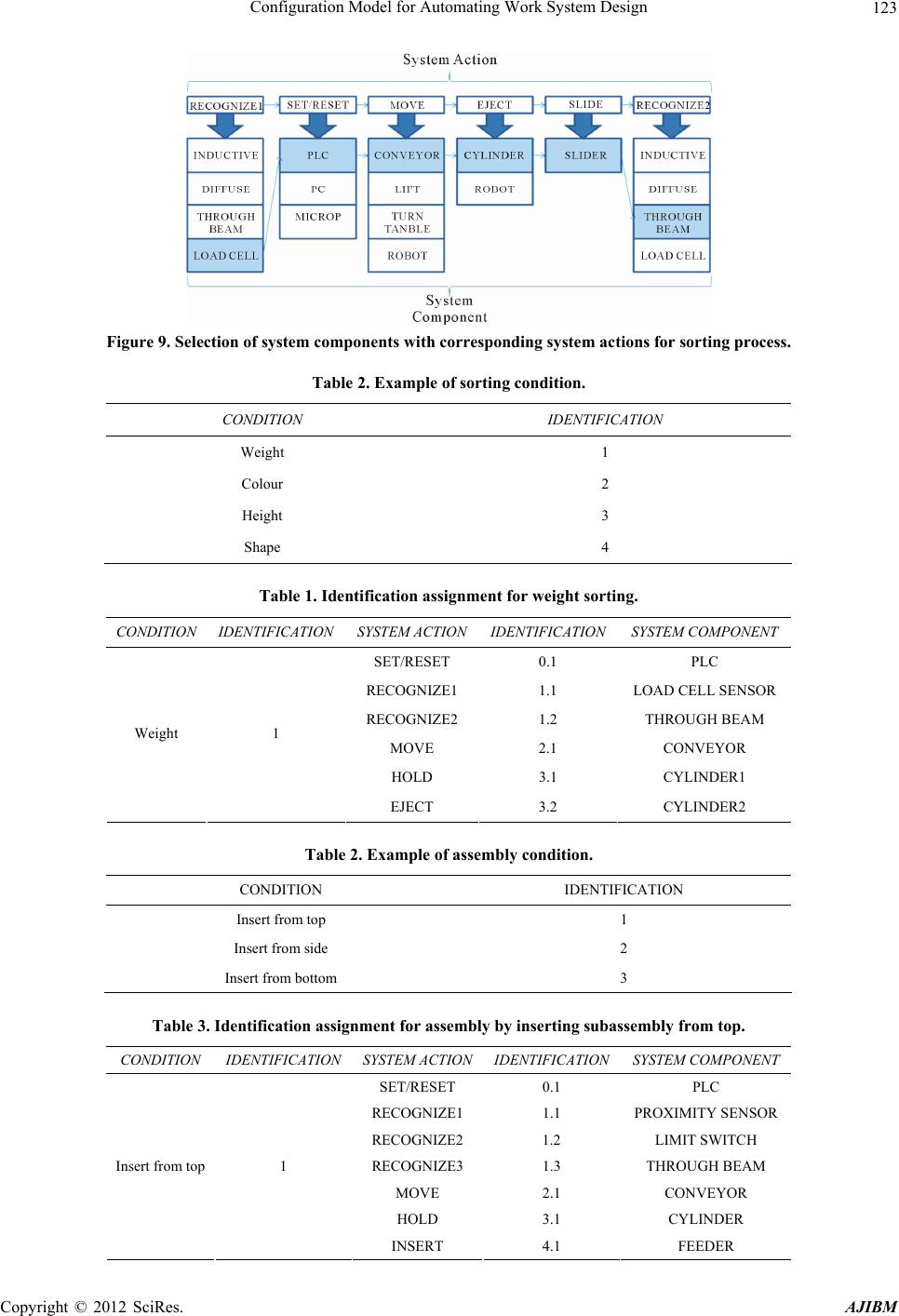 Configuration Model for Automating Work System Design 123 Figure 9. Selection of system components with corresponding system actions for sorting process. Table 2. Example of sorting condition. CONDITION IDENTIFICATION Weight 1 Colour 2 Height 3 Shape 4 Table 1. Identification assignment for weight sorting. CONDITION IDENTIFICATION SYSTEM ACTIONIDENTIFICATIONSYSTEM COMPONENT SET/RESET 0.1 PLC RECOGNIZE1 1.1 LOAD CELL SENSOR RECOGNIZE2 1.2 THROUGH BEAM MOVE 2.1 CONVEYOR HOLD 3.1 CYLINDER1 Weight 1 EJECT 3.2 CYLINDER2 Table 2. Example of assembly condition. CONDITION IDENTIFICATION Insert from top 1 Insert from side 2 Insert from bottom 3 Table 3. Identification assignment for assembly by inserting subassembly from top. CONDITION IDENTIFICATION SYSTEM ACTIONIDENTIFICATIONSYSTEM COMPONENT SET/RESET 0.1 PLC RECOGNIZE1 1.1 PROXIMITY SENSOR RECOGNIZE2 1.2 LIMIT SWITCH RECOGNIZE3 1.3 THROUGH BEAM MOVE 2.1 CONVEYOR HOLD 3.1 CYLINDER Insert from top 1 INSERT 4.1 FEEDER Copyright © 2012 SciRes. AJIBM 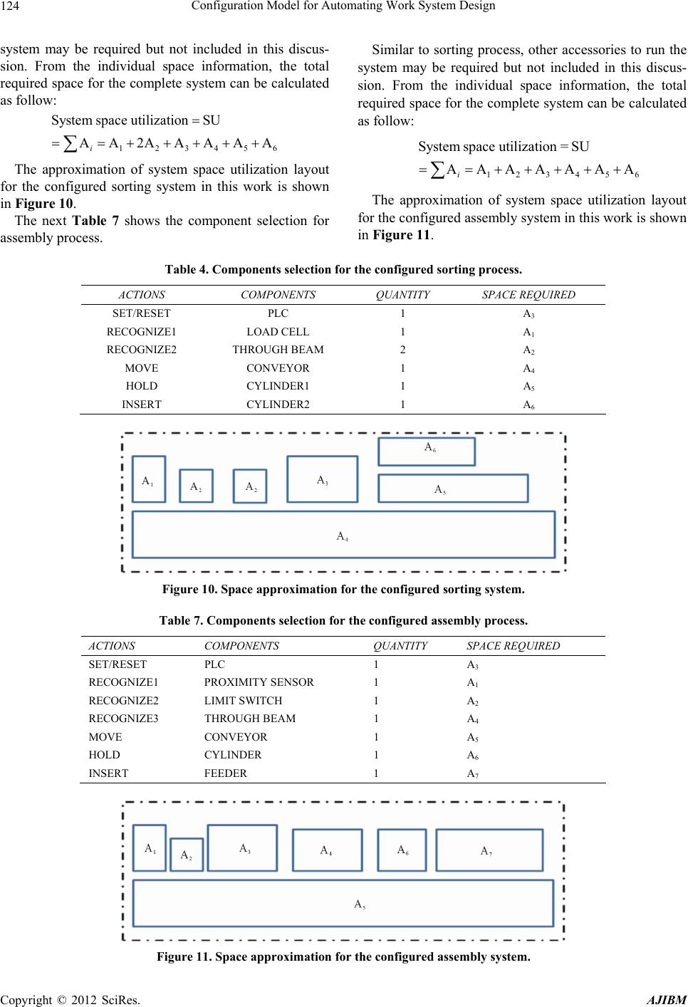 Configuration Model for Automating Work System Design 124 system may be required but not included in this discus- sion. From the individual space information, the total required space for the complete system can be calculated as follow: 12345 System space utilizationSU AA2AAAAA i 6 The approximation of system space utilization layout for the configured sorting system in this work is shown in Figure 10. The next Table 7 shows the component selection for assembly process. Similar to sorting process, other accessories to run the system may be required but not included in this discus- sion. From the individual space information, the total required space for the complete system can be calculated as follow: 123456 System spaceutilization= SU AAAAAAA i The approximation of system space utilization layout for the configured assembly system in this work is shown in Figure 11. Table 4. Components selection for the configured sorting process. ACTIONS COMPONENTS QUANTITY SPACE REQUIRED SET/RESET PLC 1 A3 RECOGNIZE1 LOAD CELL 1 A1 RECOGNIZE2 THROUGH BEAM 2 A2 MOVE CONVEYOR 1 A4 HOLD CYLINDER1 1 A5 INSERT CYLINDER2 1 A6 Figure 10. Space approximation for the configured sorting system. Table 7. Components selection for the configured assembly process. ACTIONS COMPONENTS QUANTITY SPACE REQUIRED SET/RESET PLC 1 A3 RECOGNIZE1 PROXIMITY SENSOR 1 A1 RECOGNIZE2 LIMIT SWITCH 1 A2 RECOGNIZE3 THROUGH BEAM 1 A4 MOVE CONVEYOR 1 A5 HOLD CYLINDER 1 A6 INSERT FEEDER 1 A7 Figure 11. Space approximation for the configured assembly system. Copyright © 2012 SciRes. AJIBM 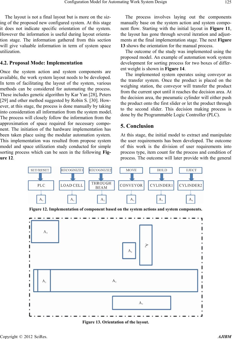 Configuration Model for Automating Work System Design 125 The layout is not a final layout but is more on the siz- ing of the proposed new configured system. At this stage it does not indicate specific orientation of the system. However the information is useful during layout orienta- tion stage. The information gathered from this section will give valuable information in term of system space utilization. 4.2. Proposal Mode: Implementation Once the system action and system components are available, the work system layout needs to be developed. In term of facilitating the layout of the system, various methods can be considered for automating the process. These includes genetic algorithm by Kar Yan [28], Peters [29] and other method suggested by Robin S. [30]. How- ever, at this stage, the process is done manually by taking into consideration all information from the system model. The process will closely follow the information from the approximation of space required for necessary compo- nent. The initiation of the hardware implementation has been taken place using the modular automation system. This implementation was resulted from propose system model and space utilization study conducted for simple sorting process which can be seen in the following Fig- ure 12. The process involves laying out the components manually base on the system action and system compo- nent flow. Starting with the initial layout in Figure 11, the layout has gone through several iteration and adjust- ments at the final implementation stage. The next Figure 13 shows the orientation for the manual process. The outcome of the study was implemented using the proposed model. An example of automation work system development for sorting process for two boxes of differ- ent weight is shown in Figure 14. The implemented system operates using conveyor as the transfer system. Once the product is placed on the weighing station, the conveyor will transfer the product from the current spot until it reaches the decision area. At the decision area, the pneumatic cylinder will either push the product onto the first slider or let the product through to the second slider. This decision making process is done by the Programmable Logic Controller (PLC). 5. Conclusion At this stage, the initial model to extract and manipulate the user requirements has been developed. The outcome of this work is the division of user requirements into process type, item count for the process and condition of process. The outcome will later provide with the general Figure 12. Implementation of component based on the system actions and system components. Figure 13. Orientation of the layout. Copyright © 2012 SciRes. AJIBM 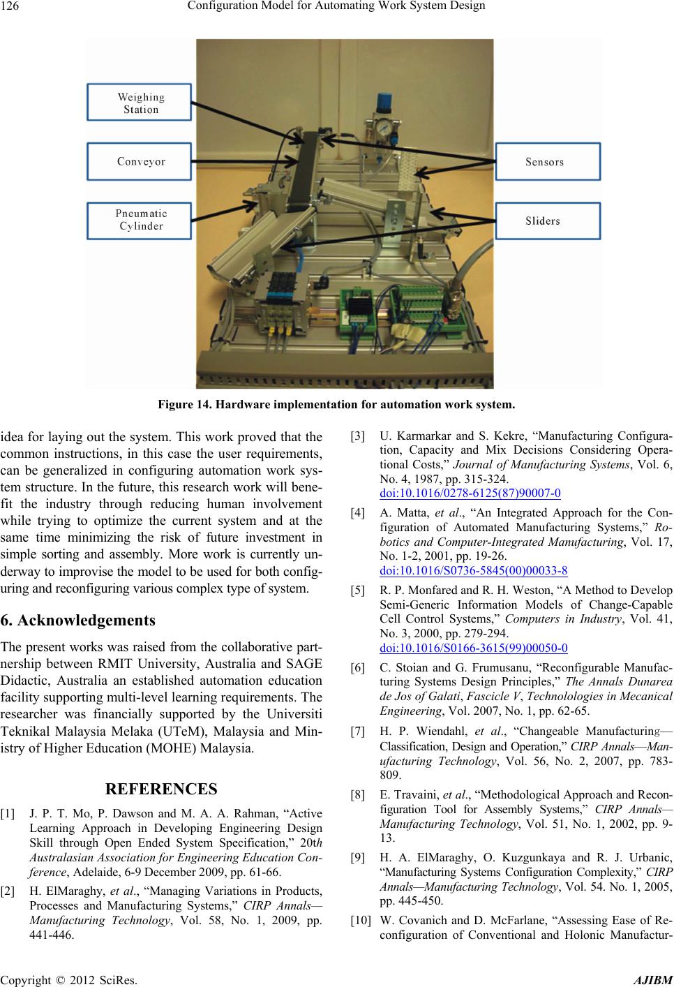 Configuration Model for Automating Work System Design 126 Figure 14. Hardware implementation for automation work system. idea for laying out the system. This work proved that the common instructions, in this case the user requirements, can be generalized in configuring automation work sys- tem structure. In the future, this research work will bene- fit the industry through reducing human involvement while trying to optimize the current system and at the same time minimizing the risk of future investment in simple sorting and assembly. More work is currently un- derway to improvise the model to be used for both config- uring and reconfiguring various complex type of system. 6. Acknowledgements The present works was raised from the collaborative part- nership between RMIT University, Australia and SAGE Didactic, Australia an established automation education facility supporting multi-level learning requirements. The researcher was financially supported by the Universiti Teknikal Malaysia Melaka (UTeM), Malaysia and Min- istry of Higher Education (MOHE) Malaysia. REFERENCES [1] J. P. T. Mo, P. Dawson and M. A. A. Rahman, “Active Learning Approach in Developing Engineering Design Skill through Open Ended System Specification,” 20th Australasian Association for Engineering Education Con- ference, Adelaide, 6-9 December 2009, pp. 61-66. [2] H. ElMaraghy, et al., “Managing Variations in Products, Processes and Manufacturing Systems,” CIRP Annals— Manufacturing Technology, Vol. 58, No. 1, 2009, pp. 441-446. [3] U. Karmarkar and S. Kekre, “Manufacturing Configura- tion, Capacity and Mix Decisions Considering Opera- tional Costs,” Journal of Manufacturing Systems, Vol. 6, No. 4, 1987, pp. 315-324. doi:10.1016/0278-6125(87)90007-0 [4] A. Matta, et al., “An Integrated Approach for the Con- figuration of Automated Manufacturing Systems,” Ro- botics and Computer-Integrated Manufacturing, Vol. 17, No. 1-2, 2001, pp. 19-26. doi:10.1016/S0736-5845(00)00033-8 [5] R. P. Monfared and R. H. Weston, “A Method to Develop Semi-Generic Information Models of Change-Capable Cell Control Systems,” Computers in Industry, Vol. 41, No. 3, 2000, pp. 279-294. doi:10.1016/S0166-3615(99)00050-0 [6] C. Stoian and G. Frumusanu, “Reconfigurable Manufac- turing Systems Design Principles,” The Annals Dunarea de Jos of Galati, Fascicle V, Technolologies in Mecanical Engineering, Vol. 2007, No. 1, pp. 62-65. [7] H. P. Wiendahl, et al., “Changeable Manufacturing— Classification, Design and Operation,” CIRP Annals—Man- ufacturing Technology, Vol. 56, No. 2, 2007, pp. 783- 809. [8] E. Travaini, et al., “Methodological Approach and Recon- figuration Tool for Assembly Systems,” CIRP Annals— Manufacturing Technology, Vol. 51, No. 1, 2002, pp. 9- 13. [9] H. A. ElMaraghy, O. Kuzgunkaya and R. J. Urbanic, “Manufacturing Systems Configuration Complexity,” CIRP Annals—Manufacturing Technology, Vol. 54. No. 1, 2005, pp. 445-450. [10] W. Covanich and D. McFarlane, “Assessing Ease of Re- configuration of Conventional and Holonic Manufactur- Copyright © 2012 SciRes. AJIBM  Configuration Model for Automating Work System Design 127 ing Systems: Approach and Case Study,” Engineering Ap- plications of Artificial Intelligence, Vol. 22, No. 7, 2009, pp. 1015-1024. doi:10.1016/j.engappai.2009.01.001 [11] A. Ferscha, et al., “Building Flexible Manufacturing Sys- tems Based on Peer-Its,” EURASIP Journal on Embedded Systems, Vol. 2008, 2008. doi:10.1155/2008/267560 [12] A. D. Toni and S. Tonchia, “Manufacturing Fexibility: A Literature Review,” International Journal of Production Research, Vol. 36, No. 6, 1998, pp. 1587-1617. doi:10.1080/002075498193183 [13] M. A. A. Rahman and J. P. T. Mo, “Development of Theoretical Reconfiguration Structure for Manufacturing Automation Systems,” International Journal of Agile Sys- tems and Management, Vol. 5, No. 2, 2012, pp. 132-150. [14] W. Lepuschitz, et al., “Toward Self-Reconfiguration of Manu- facturing Systems Using Automation Agents,” IEEE Trans- actions on Systems, Man, and Cybernetics, Part C: Ap- plications and Reviews, Vol. 41, No. 1, 2011, pp. 52-69. [15] Y. Huang, et al., “Manufacturing Execution System Ar- chitecture Supporting Cross-Grain Reconfiguration,” Jisu- anji Jicheng Zhizao Xitong/Computer In tegrated Manufac- turing Systems, Vol. 17, No. 4, 2011, pp. 747-759. [16] N. Fuller, “The House of Quality,” Supply Management, Vol. 3, No. 3, 1998, p. 44. [17] J.-C. Jiang, M.-L. Shiu and M.-H. Tu, “Quality Function Deployment (QFD) Technology Designed for Contract Manufacturing,” TQM Journal, Vol. 19, No. 4, 2007, p. 291. doi:10.1108/09544780710756205 [18] Z. Ocak, “Applying Quality Function Deployment in the Manufacturing Industry: A Review & Case Study in Pro- duction,” The Business Review, Vol. 9, No. 2, 2008, p. 4. [19] R. K. Singh, C. C. Elrod and E. A. Cudney, “Comparative Analysis of Quality Function Deployment Methodologies: A Case Study Analysis,” The Quality Management Jour- nal, Vol. 19, No. 1, 2012, p. 7. [20] Y. Z. Mehrjerdi, “Applications and Extensions of Quality Function Deployment,” Assembly Automation, Vol. 30, No. 4, 2010, p. 388. doi:10.1108/01445151011075843 [21] R. Mahanti, “The Application of Quality Function De- ployment to User Interface Design,” The Quality Man- agement Journal, Vol. 16, No. 1, 2009, p. 29. [22] C.-H. Liu, “A Group Decision-Making Method with Fuzzy Set Theory and Genetic Algorithms in Quality Function Deployment,” Quality and Quantity, Vol. 44, No. 6, 2010, p. 1175. doi:10.1007/s11135-009-9304-1 [23] A. Olewnik and L. Kemper, “Limitations of the House of Quality to Provide Quantitative Design Information,” The International Journal of Quality & Reliability Manage- ment, Vol. 25, No. 2, 2008, p. 125. doi:10.1108/02656710810846916 [24] J.-S. Shin, K.-J. Kim and M. J. Chandra, “Consistency Check of a House of Quality Chart,” The International Journal of Quality & Reliability Management, Vol. 19, No. 4, 2002, p. 471. doi:10.1108/02656710210421535 [25] S. Ratchev, H. Hirani and M. Bonney, “Knowledge Based Formation of Re-Configurable Assembly Cells,” Journal of Intelligent Manufacturing, Vol. 18, No. 3, 2007, pp. 401- 409. doi:10.1007/s10845-007-0031-y [26] H. F. Manesh, D. Schaefer and M. Hashemipour, “Infor- mation Requirements Analysis for Holonic Manufactur- ing Systems in a Virtual Environment,” The International Journal of Advanced Manufacturing Technology, Vol. 53, No. 1-4, 2011, pp. 385-398. doi:10.1007/s00170-010-2822-0 [27] T. K. Yan, “Genetic Algorithms, Function Optimization, and Facility Layout Design,” European Journal of Op- erational Research, Vol. 63, No. 2, 1992, pp. 322-346. doi:10.1016/0377-2217(92)90034-7 [28] B. A. Peters and M. Rajasekharan, “A Genetic Algorithm for Determining Facility Design and Configuration of Single-Stage Flexible Electronic Assembly Systems,” Jour- nal of Manufacturing Systems, Vol. 15, No. 5, 1996, pp. 316-324. doi:10.1016/0278-6125(96)84194-X [29] S. L. Robin, “Automated Facilities Layout: Past, Present and Future,” Automation in Construction, Vol. 9, No. 2, 2000, pp. 197-215. doi:10.1016/S0926-5805(99)00005-9 [30] S. L. Robin, “Automated Facilities Layout: Past, Present and Future,” Automation in Construction. Vol. 9, No. 2, 2000, pp. 197-215. Copyright © 2012 SciRes. AJIBM
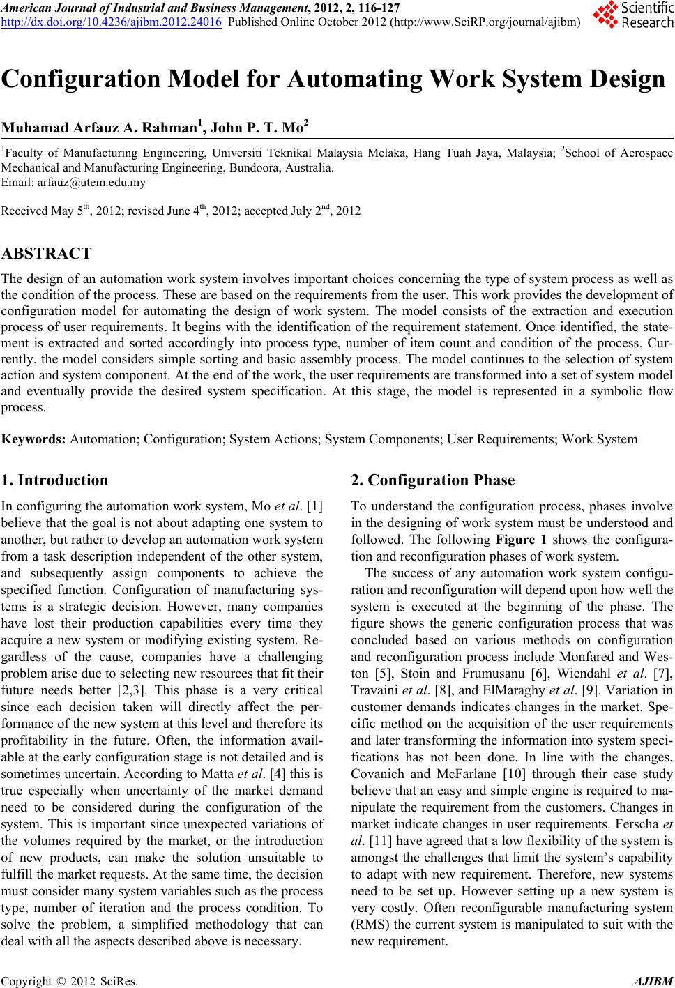
|