Journal of Minerals and Materials Characterization and Engineering, 2012, 11, 989-994
Published Online October 2012 (http://www.SciRP.org/journal/jmmce)
FEM Simulation and Experimental Validation of
Cold Forging Behavior of LM6 Base Metal Matrix
Composites
Hillol Joardar1*, Goutam Sutradhar2, Nitai Sudar Das1
1Department of Mechanical Engineering, C.V. Raman College of Engineering, Bhubaneswar, Orissa, India
2Department of Mechanical Engineering, Jadavpur University, Kolkata, West Bengal, India
Email: *hillol_joardar@yahoo.com, hillol_joardar@yahoo.com
Received August 15, 2012; revised September 20, 2012; accepted September 30, 2012
ABSTRACT
The present paper examines the deformation behavior of solid cylinders of an aluminium alloy metal matrix composite
(MMC) undergoing axial compression in a Universal Testing Machine under dry condition. The composite was pre-
pared by the stir casting method from LM6 aluminium alloy using silicon carbide particles (SiC) as reinforcing agent.
The effect of weight percentage of silicon carbide on microstructure, hardness and upsetting load is studied. The friction
factor at die metal interface is evaluated by ring compression tests and its effect on non-uniform deformation is investi-
gated. The experimental results are finally compared with those obtained by FEM simulation.
Keywords: LM6-SiC MMC; Hardness; Microstructure; Forging; FEM
1. Introduction
In recent years considerable attention has been directed
to the study of aluminium metal matrix composites be-
cause of their growing applications in aerospace and
automotive industries [1,2]. This is not only due to their
superior mechanical and thermal properties (high specific
strength, excellent wear resistance, high thermal conduc-
tivity [2,3]) but is also to a large extent due to the fact
that these properties can be manipulated by careful con-
trol of the relative amounts and distribution of the ingre-
dients and the processing conditions to suit specific re-
quirements [2].
Metal matrix composites can be produced by the pow-
der metallurgy method [4,5], by spray deposition tech-
nique [6] and by stir casting [7-11]. For discontinuous
metal matrix composites the last method is generally
accepted as a particularly promising route currently prac-
ticed commercially. Its advantages lie in its simplicity,
flexibility and applicability to large quantity production
at relatively low cost.
Presence of silicon carbide particles influences the
mechanical properties and the deformation behavior of
the aluminium metal matrix in a number of ways. The
proof stress (0.2%) and ultimate tensile strength of alu-
minium tend to increase while its toughness and ductility
decrease as the volume fraction of SiC particles in the
matrix increases or when its particle size decreases [12].
The brittle fracture behavior of these composites is also
found to be affected by the weight fraction of the rein-
forcing agent [13]. Secondary processing and heat treat-
ment operations are seen to contribute to the performance
of these materials. Thus crack formation in axial com-
pression of Al/SiC solid cylinders made by powder met-
allurgy is found to be suppressed by subjecting these
cylinders to an annealing or quenching treatment prior to
the deformation process [14]. Parts having undergone
forming operations such as forging and extrusion tend to
have refine grain structure resulting in their improved
performance. It must be stated, however that most of the
studies on mechanical behavior and material characteri-
zation of Aluminium-SiC metal matrix composites have
been limited to materials prepared by powder metallurgy.
For composites prepared by ingot metallurgy similar
studies are relatively less.
In the present investigation an attempt is made to
evaluate the effect of SiC particles on the microstructure
and mechanical behavior of an aluminium alloy compo-
site (LM6/SiC) made by stir casting. Microstructure stu-
dies of caste samples have been carried out using an op-
tical microscope to look into the degree of wettability
and segregation of the reinforcing particles. Micro-
hardness and compression tests were also performed to
study the effect of SiC on the forgeability of caste metal
matrix. The experimental results are finally compared
*Corresponding author.
Copyright © 2012 SciRes. JMMCE
H. JOARDAR ET AL.
990
with those obtained by finite element simulation.
2. Experimental Procedure
2.1. Materials and Method
The composite for the present study was prepared from
LM6 aluminium alloy using silicon carbide particles
(approximately 400 mesh size) as reinforcing agents. The
aluminium alloy was first melted in a resistance furnace
and 3 wt% of magnesium was subsequently added to the
molten metal. This was because magnesium is known to
favour formation of a strong bond between the matrix
and the reinforcing particles by decreasing the surface
energy (wetting angle). Addition of pure magnesium also
enhances the fluidity of molten aluminium. Preheated
SiC particles (temperature 850˚C - 900˚C) in varying
weight fractions (5 wt% - 12.5 wt%) was then added to
the melt and the mix was mechanically stirred at a tem-
perature of 750˚C by an impeller at a stirring speed of
about 400 rpm - 500 rpm. The melt was poured at a tem-
perature of 745˚C into silica sand moulds for preparation
of the test samples. The composition of LM6 alloy is
given in “Table 1”.
2.2. Microscopy
For microscopic examination specimens of cast compos-
ites of 10 mm diameter and 15 mm thickness were first
ground through 320, 400, 600, 800, 1200 and 1500 grit
emery papers followed by polishing by 6 μm diamond
paste. The samples were then etched with Keller’s re-
agent (2.5 ml HNO3, 1.5 ml HCl, 1.0 ml HF, 95.0 ml
Water) and dried by an electric drier. The microstructure
was observed by a metallurgical microscope (Olympus,
CK40M).
2.3. Hardness Measurements
Micro-hardness measurements were also carried out us-
ing a LEICA VMHT micro-hardness tester at 100 gms
load with a dwell time of 10 seconds to study the varia-
tion of hardness with different wt% of SiC.
2.4. Compression Test
For forgeability tests, cylindrical specimens of L/D ratio
equal to 1.5 (height L = 15 mm, Diameter D = 10mm)
were compressed axially on a 100-ton hydraulic press at
room temperature under dry condition. To plot the stress-
strain diagram, the tests were interrupted at every 5 mm
reduction in height and the corresponding load P and the
equatorial diameter DE were measured. The stress (σ) and
the strain (ε) were then calculated from the equations:
E
PA
(1)
where, 2
π4
E
E
A
D was the area of the equatorial
plane and
ln o
LL
(2)
where L0 was the initial height and L the current height of
the cylinder. The tests were continued till cracks ap-
peared at the free surface and was stopped when these
cracks grew sufficiently large leading to the collapse of
the specimens. The forgeability limit was taken to be the
height strain at which the cracks were first observed on
the free surface of the specimen.
2.5. Finite Element Simulation
Finite element simulation of the cold upsetting process
under un-lubricated condition was carried out with the
help of DEFORM-3D software using the Lagrangian
formulation. The coefficient of friction required for the
simulation was obtained from the ring compression test.
2.6. Determination of Coefficient of Friction
In metal forming interface friction plays an important
role. It controls the magnitude of the redundant work, the
magnitude of the metal forming load and the stress and
strain distribution in the deforming medium. The inter-
face friction may be quantified either by a friction factor
m (mk
, k = shear stress of work material) or a coef-
ficient of friction µ (Coulomb’s law, p

). In the
present study Coulomb’s law of friction was assumed at
the interface between the die and the deforming billet and
the coefficient of friction was determined by the ring
compression test as suggested by Male & Cockcroft [14].
Figure 1(a) shows [15] the calibration curves for de-
termination of coefficient of friction and the geometry of
a ring before and after compression is presented in Fig-
ure 1(b).
3. Results and Discussions
The microstructures of the caste and polished samples as
revealed by a metallurgical microscope are presented in
Figure 2. In these microstructures the dark areas rep-
resent the ceramic phase where as the metallic phase ap-
pears white. The microstructures show a reasonably uni-
Table 1: Chemical composition (LM6).
Elements Si Cu Mg Fe Mn Ni Zn Pb Sb Ti Al
Percentage
(%) 10 - 13 0.1 0.1 0.6 0.5 0.1 0.1 0.1 0.05 0.2 Remaining
Copyright © 2012 SciRes. JMMCE
H. JOARDAR ET AL. 991
(a)
(b)
Figure 1. (a) Friction calibration curves in terms of co-
efficient of friction; (b) Ring compression specimen (a) be-
fore and (b) after compression.
form distribution of SiC particles in the matrix with only
slight macro-segregation in some areas. This indicates
good wetting of the silicon carbide particles by the mol-
ten metal and excellent interfacial bonding between the
two phases.
The hardness (Figure 3) and the compressive strength
(a)
(b)
(c)
(d)
Figure 2. Microstructures of cast LM6/SiC composites (a)
SiC: 5%; (b) SiC: 7.5%; (c) SiC: 10%; (d) SiC: 12.5%.
(Figure 4) of the composites are found to increase with
increase in the weight fraction of the reinforcing particles.
The compressive strength here refers to the average axial
stress σ (Equation (1)) over the equatorial plane. The
Copyright © 2012 SciRes. JMMCE
H. JOARDAR ET AL.
992
Figure 3.Variation of hardness with weight percentage of
SiC.
Figure 4. Variation of equatorial stress with height strain.
above increase may be due to the increase in dislocation
density at the interfaces of the hard carbide particles and
the soft metal matrix or may be the result of the income-
patibility in the elastic and the plastic behavior of the two
phases due to their differential thermal expansion. A re-
duction in the grain size of the metal matrix due to addi-
tion of silicon carbide might also have contributed to this
improvement in the mechanical properties.
Two types of cracks are seen in the forging of LM6
based composites. These are the speed cracks and the
surface cracks. Friction at the interface between the die
and the billet during axial compression results in inho-
mogenity of deformation and consequent barreling of the
free surface of the billet. This gives rise to high tensile
stresses leading to speed cracking. Surface tearing occurs
when the surface temperature exceeds the melting tem-
perature of the phase having the lowest melting point. In
the present study surface tearing was observed at room
temperature. This might be due to the conversion of work
of compression into thermal energy resulting in tem-
perature rise of the billets. It was also observed that
cracks were initiated only after compression of the billets
by about 28% - 32% depending on the weight fraction of
the SiC. The specimens collapsed completely after a re-
duction in height by about 34% - 38%.
4. FEM Simulation
As a basis for comparison finite element simulation of
the upsetting process was carried out using DEFORM-
3D software that uses implicit Lagrangian formulation
for the analysis. For this purpose the material constitutive
equation was assumed as:
n
K
(3)
where K is the stress coefficient, n is the strain hardening
index,
is the effective stress,
is the effective
strain, K and n were both determined from compression
tests and used for simulation.
The other data used for simulation were Poisson’s ra-
tio ν = 0.33 and coefficient of friction µ = 0.34.
The coefficient of friction was determined from the
ring compression test as mentioned in 2.6.
The four-node quadrilateral elements with 3168 nodes
and 3040 elements are adopted to discretise the cylinder
and that of a cylinder before and after compression are
shown in Figure 5.
In Figures 6 and 7 the experimentally measured pa-
rameters are compared with those obtained from the fi-
nite element simulation. The increase in radius of the
equatorial plane with height reduction by both the meth-
ods show excellent agreement with each other (Figure 6).
Similar conclusion is also established when flow stress in
the equatorial plane is considered (Figure 7). Simulated
results for stress, strain and velocity at different stages of
upsetting are also presented in Figures 8-10.
5. Conclusions
The significant conclusions from the present study on
(a) (b)
Figure 5. FEM – model of the sample (a) before and (b)
after compression.
Copyright © 2012 SciRes. JMMCE
H. JOARDAR ET AL.
Copyright © 2012 SciRes. JMMCE
993
Figure 6. Variation of equatorial diameter with height re-
duction. Comparison of results from experiment and simu-
lation (5 wt% SiC).
Figure 7. Variation of σ with ε. Comparison of experimental
and simulated results (5 wt% and 12.5 wt% of SiC).
Figure 8. Simulation results showing effective stress distribution at different stages of compression (5 wt% SiC).
Figure 9. Simulation results showing distribution of Von-mises strain at different stages of compression (5 wt% SiC).
LM6/SiC aluminium alloy composites are as follows: Both hardness and strength of the composites increase
with increase in SiC content. Homogeneous LM6/SiC aluminium alloy composites
can be successfully prepared using liquid metallurgy
techniques.
Cylindrical preform can be successfully compressed
to a height reduction by 28% - 32% without fracture.
H. JOARDAR ET AL.
994
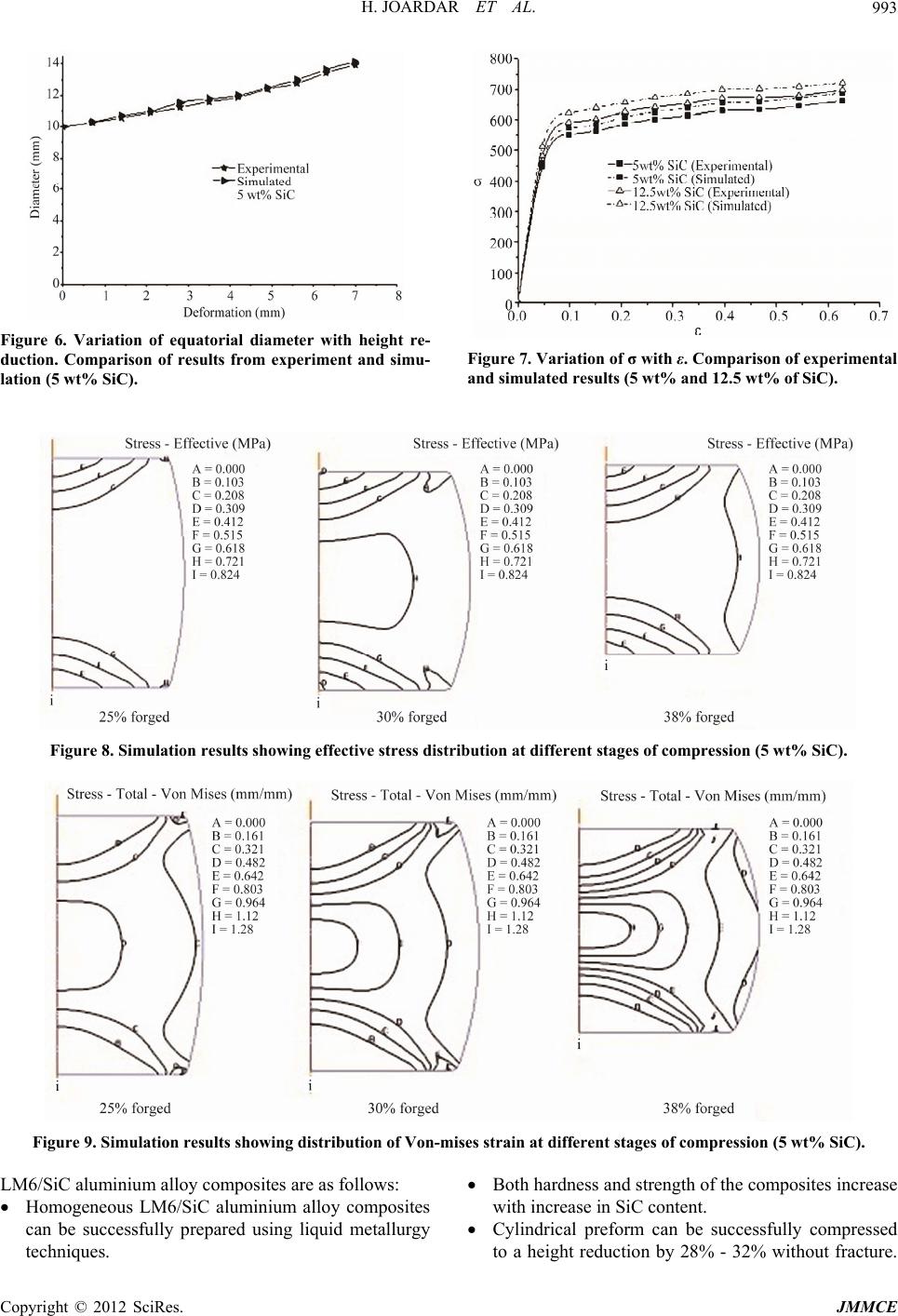
Figure 10. Simulation results showing variation in velocity within the specimen at different stages of compression (5 wt%
SiC).
Preforms collapse only after a reduction in height by
34% - 38%.
Finite element simulation of the deformation behavior
of the composite can be carried out as that for a ho-
mogeneous material.
There is close agreement between the simulated re-
sults with experiment.
REFERENCES
[1] G. B. V. Kumar, C. S. P. Rao and N. Selvaraj, “Me-
chanical and Tribological Behavior of Particulate Rein-
forced Aluminum Metal Matrix Composites—A Review,”
Journal of Minerals & Materials Characterization & En-
gineering, Vol. 10, No. 1, 2011, pp. 59-91.
[2] G. B. V. Kumar, C. S. P. Rao, N. Selvaraj and M. S.
Bhagyashekar, “Studies on Al6061-SiC and Al7075-Al2O3
Metal Matrix Composites,” Journal of Minerals & Mate-
rials Characterization & Engineering, Vol. 9, No. 1,
2010, pp. 43-55.
[3] M. Singla, L. Singh and V. Chawla, “Study of Wear
Properties of Al-SiC Composites,” Journal of Minerals &
Materials Characterization & Engineering, Vol. 8, No.
10, 2009, pp. 813-819.
[4] F. L. Matthew and R. D. Rawlings, “Composite Materials:
Engineering and Science,” Chapman & Hall, London,
1994.
[5] F. O. gel Bedir, “Investigation of Hardness, Microstruc-
ture and Wear Properties of SiC-P Reinforced Al Com-
posites,” Proceeding of the 11th International Conference
on Machine Design and Production, Turkey, 13-15 Oc-
tober, 2004.
[6] V. Laurent, C. Rado and N. Eustathopoulos, “Wetting
Kinetics and Bonding of Al and Al Alloys on α-SiC,”
Materials Science and Engineering: A, Vol. 205, No. 1-2,
1996, pp. 1-8.
[7] A Martin and J. Llorca, “Mechanical Behaviour and Fail-
ure Mechanisms of a Binary Mg 6%Zn Alloy Reinforced
with SiC Particulates,” Materials Science and Engineer-
ing: A, Vol. 201, No. 1-2, 1995, pp. 77-87.
[8] R. A. Saravanan and M. K. Surappa, “Fabrication and
Characterisation of Pure Magnesium-30 Vol.% SiCP Par-
ticle Composite,” Matrials Science and Engineering: A,
Vol. 276, No. 1-2, 2000, pp. 108-116.
[9] J. Hashim, L. Looney and M. S. J. Hashim, “Metal Matrix
Composites: Production by the Stir Casting Method,”
Journal of Material Processing Technology, Vol. 92-93,
1999, pp. 1-7. doi:10.1016/S0924-0136(99)00118-1
[10] A. Bochenek and K. N. Bbraszezynska, “Structural
Analysis of the MgAl5 Matrix Cast Composites Contain-
ing SiC Particles,” Materials Science and Engineering: A,
Vol. 290, No. 1-2, 2000, pp. 122-127.
[11] W. Zhou and Z. M. Xu, “Casting of SiC Reinforced
Metal Matrix Composites,” Journal of Material Process-
ing Technology, Vol. 63, No. 1-2, 1997, pp. 358-363.
[12] C. N. Devi, V. Mahesh and N. Selvaraj, “Mechanical
Characterization of Aluminium Silicon Carbide Compos-
ite,” International Journal of Applied Engineering Re-
search, Vol. 1, No. 4, 2011, pp. 793-799.
[13] S. Dikshit, V. Gurjar, R. Dasgupta, S. C. Turvedi , K. K.
Pathak and A. K. Jha, “Studies on Cold Upsetting Be-
haviour of AA2014-Based Metal Matrix Composites,
FEM Simulation, and Compareison with Experimental
Results,” Journal of Material Science, Vol. 45, No. 15,
2011, pp. 4174-4179.
doi:10.1007/s10853-010-4507-3
[14] C. Badini, G. M. La Vecchia, P. Fino and T. Vale, “Forg-
ing of 2124/SiCp Composite Prelimnary Studies of the
Effects on Microstructure and Strength,” Journal of Ma-
terials Processing Technology, Vol. 116, No. 2-3, 2011,
pp. 289-297. doi:10.1016/S0924-0136(01)01056-1
[15] H. Sofuoğlu, H. Gedikli and J. Rasty, “Determination of
Friction Coefficient by Employing the Ring Compression
Test,” Transactions of ASME, Journal of Engineering
Materials and Technology, Vol. 123, No. 3, 2001, pp.
338-348. doi10.1115/1.1369601
Copyright © 2012 SciRes. JMMCE