Circuits and Systems
Vol.07 No.10(2016), Article ID:69872,17 pages
10.4236/cs.2016.710263
Managing of Smart Micro-Grid Connected Scheme Using Group Search Optimization
S. Bhagawath1, S. Edward Rajan2
1Department of Electronics and Communication Engineering, Arunachala College of Engineering for Women, Vellichanthai, India
2Department of Electrical and Electronics Engineering, Mepco Schlenk Engineering College, Sivakasi, India

Copyright © 2016 by authors and Scientific Research Publishing Inc.
This work is licensed under the Creative Commons Attribution International License (CC BY).
http://creativecommons.org/licenses/by/4.0/


Received 21 May 2016; accepted 29 May 2016; published 19 August 2016
ABSTRACT
This article introduces a group search optimization (GSO) based tuning model for modelling and managing Smart Micro-Grids connected system. In existing systems, typically tuned PID controllers are engaged to point out the load frequency control (LFC) problems through different tuning techniques. Though, inappropriately tuned PID controller may reveal pitiable dynamical reply and also incorrect option of integral gain may even undermine the complete system. This research is used to explain about an optimized energy management system through Group Search Optimization (GSO) for building incorporation in smart micro-grids (MGs) with zero grid-impact. The essential for this technique is to develop the MG effectiveness, when the complete PI controller requires to be tuned. Consequently, we proposed that the proposed GSO based algorithm with appropriate explanation or member representation, derivation of fitness function, producer process, scrounger process, and ranger process. An entire and adaptable design of MATLAB/SIMULINK also proposed. The related solutions and practical test verifications are given. This paper verified that the proposed method was effective in Micro-Grid (MG) applications. The comparison results demonstrate the advantage of the proposed technique and confirm its potential to solve the problem.
Keywords:
Micro-Grid, PI Controller, Energy Management, Group Search Optimization, Distributed Generation

1. Introduction
Many changes have occurred in the electricity sector to improve the energy efficiency and environmental sustainability of generation, transport and final use segments, involving the need to update and improve the electric grids [1] - [3] in past years. Another significant change regards the spread of the so-said dispersed or distributed generation (DG), including renewable sources generation plants (such as PV or wind micro-turbine) and high efficiency production systems (such as gas micro-turbine or CHP) [4] . Distributed power generation systems are usually supposed to become a crucial electric power supply system for the upcoming generation [5] . In traditional power systems, the reliability impact could be significant when a large amount of variable DG is integrated on it. It is well known that the chaotic phenomena in the existing distribution grids will occur when the DG penetration reach a high level compared to the net energy, causing network congestion and so compromising the energy quality by voltage and frequency disturbances. In traditional power systems, the reliability impact could be significant when a large amount of variable DG is integrated on it. It is well known that the chaotic phenomena in the existing distribution grids will occur when the DG penetration reach a high level compared to the net energy, causing network congestion and so compromising the energy quality by voltage and frequency disturbances.
At the same time, another concept related to the distribution grid has been proliferating: the MG concept. A MG is a small electricity network, generally in LV level, connected to other MGs and/or to the main grid (generally in medium voltage, using a single point of connection (PC). A MG generally includes DG, electrical loads of different types (i.e., PHEVs) and energy storage devices in a reduced space. In a MG, each actor could take part into: reactive power supply and voltage control; active power supply and frequency control; and fault ride-through capability and power quality control (flicker, harmonics) [6] .
Group Search Optimization (GSO) is a naturally sensitive algorithm which is taken by the animal (lions and wolves) food finding activities. He et al. [7] projected GSO in 2006, and argued the consequences of considered limits on the presentation of GSO in 2009 [8] . GSO utilizes a particular structure, in which individuals are separated into three classes and develop independently. This structure is verified to be efficient and strong on resolving multimodal issues [8] . Shen et al. [9] examined the presentation of GSO and finished that GSO is a substitute for controlled optimization. In addition, GSO is used to resolve non-convex economic transmit issue [10] , distribution network reconfiguration [11] , mutual heat and power economic transmit issue [12] , etc., because of its high effectiveness. Attraction of these studies, in this paper, we proposed an energy management approach using GSO that provides a new concept for buildings integration in smart grids. Our major contributions are summarized as follows: i) GSO based energy management approach that provides a new concept for buildings integration in smart grids. ii) Derive a multi-objective fitness function that satisfied four objectives, iii) Simulation of the proposed approach to demonstrate its performance against some of existing approaches.
The remainder of this paper is organized as follows: Section 2 reviews the related works on energy management approach in MGs. In Section 3, the system description and the proposed approach is formulated. In Section 4, we present the experimental results. Finally, Section 5 concludes the work.
2. Review of Related Works
In related researches, numerous connected tasks are accessible which depend on designing and control of micro grid. Some of them are given here. To optimize the method of the microgrid, a stylish energy management system (SEMS) has been obtainable by Chen et al. [13] . The SEMS include power forecasting module, energy storage system (ESS) management module and optimization module. The necessity of energy storage is to be optimized across multiple-time steps, concerning the power of energy price formation, their economics are mostly compound. The conclusion of ESS module is to discover the optimal operation methods. Additionally, the multiple-time set points of the storage tool and money-making management of ESS are calculated. Elegant management of ESS, economic load dispatch and process optimization of distributed generation (DG) were completely easy for a single-object optimization difficulty in the SEMS. And then, a matrix real-coded genetic algorithm (MRC-GA) optimization module was described to achieve a useful method for load management, mutually with three dissimilar process strategies.
Conti et al. [14] , have been proposed that the inside of a medium-voltage islanded micro grid, and an optimization process which permits for the optimal dispatching related with scattered generator and storage systems. The network has been guided by programmable and nonprogrammable generators. Their optimization has been implemented by a niching evolutionary algorithm (NEA) of which was capable to follow the multiple optima and the divergence with the target task of their neighbourhood. NEA is revealed a probable for improving the definite appearance related with standard algorithms demanded for optimal power-flow computations with electrical power systems through elimination of falling straight into local optima. Their exacting optimization process has been implemented by using of evaluate micro grid and verified by computer models. Their exacting projected mathematical solutions illustrates that how the solutions might be improved the real micro grid productions irrespective of the real network functional situation with all of the thought to be belongings.
A centralized control system which balances parallel process of different distributed generation (DG) inverters in the micro grid maintains which is taken from Tan et al. [15] . The exacting control intend for that DG inverters exploits a Model Predictive Control (MPC) algorithm that allowed for quicker computational time with observe to important power systems by optimizing this steady-state as well as the passing control trouble independently. In order to coordinate load sharing connecting different DG elements in the way of both grid-con- nected and islanded procedures, a benchmark energy management system was implemented for that micro grid. Due to the dissimilar check predicaments, the graph impression of their exacting recommended control system was measured by model study.
In the micro grid (MG), the method depends on the cost-benefit review for an optimal aspect of an energy storage system maintains to be proposed by Chen et al. [16] . By rotating detachment for MG, their exacting recommended method was estimated the element assurance difficulty. The time series as well as feed forward neural network method was implemented for predicting the real wind speed as well as photo voltaic radiations respectively and the predicting faults concluded additionally estimated. Two type of mathematical are previously1 generated for the islanded as well as grid-connected kinds of MGs. The major issue was developed like a mixed linear integer problem (MLIP), which has been pressed all over AMPL (A Modelling Language for Mathematical Programming). The definite ability in their recommended scheme was legitimate basically by case reviews the position where the optimal system energy storage grading for the islanded as well as grid associated MGs finished up exposed. Concerning the grid-connected as well as islanded MGs, their exacting recommended technique results show which the optimal size relating BESS subsist as well as changes.
Dasgupta et al. [17] have projected existing control method inside the a-b-c frame, for a three-phase inverter. Their projected method appeared to be used on manage the active and spontaneous electrical power stream by the renewable energy basis with a three-phase widespread micro grid system. Within the survival of benchmark nonlinear loads, their individual projected control system not really controls the grid power flow but reduces the grid current complete harmonic bend. This organize system sort the grid current engaged into report the grid voltage disturb, harmonics as well as disturb in line side inductors. Their projected control system offers much improved general concert within the conventional multiple relative-integral and relative resonant control methods on description of the need of the PARK’s alteration blocks mutually with stage lock loop requirement within the control formation. To take care of disturbances, both with grid voltages and in line side inductors, an original inverter designing method appeared to be furthermore obtainable. They have authenticated which their individual projected method solution appeared to be efficiently.
Mohammadi et al. [18] have investigated about an optimal position associated with variable structure of owed production appearing that sovereign private sector in a distribution system below pool beside with hybrid based electricity market to be capable to manage reliable require electrical power by using of bilateral agreement for trade preset value electrical power using exacting price value as in every state related with market during upstream network had been obtainable beside with argued. They considered GA-based Tabu Search scheme (GATS) beside with checked to be capable to optimal position associated with DG elements by using of exacting capacity but using adaptable types for optimizing net current value inclined to economical, technical, beside with market restraints. The costs include capital cost, replacing cost, process along with servicing cost, fuel cost, manufacturing cost, along with reliability development cost.
Pablo Arboleya et al. [19] have developed a concept for building integration in MGs with zero grid-impact so improving the MG efficiency. These aims were shown to be achievable with an intelligent system, based on a dc/ac converter connected to the building point of coupling with the main grid. This system provided active and reactive power services also including a dc link where storage, generation, and loads can be installed. The system employed for validation was a prototype available at ENEA Laboratories (Italian National Agency for New Technologies). A complete and versatile model in MATLAB/SIMULINK is also presented.
Waleed Al-Saedi et al. [20] have launched a vast optimal power flow controller for any value associated micro grid depends on a novel real-time self-tuning technique. The principle finished up to manage the real dynamic and also automatic electrical power between the major grid and the micro grid contains Distributed Generation (DG) elements. The exacting controller system contains a huge internal current control loop and also an external electrical power control loop depends on a novel synchronous orientation structure and the usual PI regulators. The electricity power controller is finished being produced for active?reactive electrical power (PQ) control method. Particle Swarm Optimization (PSO) is being a rational searching algorithm that had been implemented for real-time self-tuning in the electrical power control limits. That they improved a method, the necessary load power is finished being donated similarly between the micro grid and the effectiveness using the PSO algorithm all over the load alteration.
3. System Models and Proposed Method
3.1. System Modal and Its Description
The common formats of the Custom power device (CPD) established at one of the Italian National Agency for New Technologies Energy and a Sustainable Economic Development (ENEA) building is illustrated in Figure 1. The general method of Custom Power Device (CPD) is revealed in Figure 1, which contains two dissimilar divisions such as, (1) ac subsystem, (2) dc subsystem. The ac subsystem is related to the major grid and also joined to the building loads. The dc subsystem includes energy storage system depend on Li-Po batteries. In the dc side, there are also dc loads, a voltage limiter resistor (VLR) for over-voltage defence and a PV generator (PV module). The obtainable Custom power device (CPD) arrangement and explanation is taken from the research [19] .
In the next subsections, the different elements that compose the CPD will be described.

Figure 1. General system of the Custom Power Device (CPD).
A. Li-PO Batteries: The energy storage system is depending on Li-Po batteries. The entire module is repre- sented by 280 cells linked in sequence with charged energy storage of 70 Wh per cell. The entire pack capacity is 16 kWh. The system is capable to release at a greatest rate of 20 kW in 15 min or 10 kW in an hour. The relation between the greatest output power and the charged energy is 4 - 8 h−1. The greatest functioning temperature is 45˚C at a comparative humidity range of 40% - 90%. The approximate life is about 2000 cycles at 80% release. The batteries pack charged voltage is 270 V at complete charge. Though, the pack is divided into numerous parts with voltages not larger than 60 V.
The battery pack is linked to the 600 V dc bus by using of a bidirectional dc?dc Buck-Boost converter. The BMS handle the converter demanding to maintain a stable voltage in the dc bus but preventive the charge and discharge charge to certify the accurate process of the battery pack. A complete description of this manage will be given in the next part. The BMS obtains the cells voltage, current, and temperature so it also calculates the storage system state of charge. The dc bus over-voltage defence is also certified by a 60 VLR of 60 linked by a chopper.
B. Main AC-DC Converter: The power converter has been constructed by using concrete condition static apparatus; it is furnished with IGBTs. The controlling over-voltages must not beat 200 V at complete power. For this reason particular preventive courses are integrated. IGBTs are also furnished with recognition circuit de-saturation. The recognition diffusion has been nearby done with a hardware circuit associated to the anode of every transistor and must guide to the instant detain of its transmission. At the same time, a jamming signal should be sent, through the logic control, to seize of the entire converter. The overheating defence of the device is realized with temperature sensors within the semiconductor module. The inactive converter is offered with suitable input and output sort for restraining conflict, according to the directions 89/336/EEC and 92/31/EEC. The association to the 400 V ac grids is fulfilled with the needs of the Italian Standard CEI 0-21. The 600 V dc bus-bars are sized to attach both a dc load with a greatest power of 20 Kw and a construction system with a highest power of 30 kW. A recognition and defence system offers the information about the apparatus position: power deliver for the electronics out of scope, communication mistake with Digital Signal Processor, bar voltage out of scope, inverter over-temperature, outflow currents to ground, gear time out, inverter over current, defence IGBT modules, thermal security inverter, line voltage out of scope, and low line voltage alarm. The rule of the major converter will be extremely illustrated in the next part.
C. Loads: The loads are located at the ac side and at the dc side of the major converter. In the ac side, the load is the ENEA building utilization, which can swing between 36 and 228 kW. In the dc side, the loads are collected by a few supplementary dc loads being the majority significant the system freshening. The entire amount of dc load is about 5 kW.
D. PV module control: The PV module is connected to the dc bus through a unidirectional dc/dc Buck−Boost converter. If the reference voltage is higher than the measured value,  duty will be reduced, otherwise it will be increased. A scheme of the control system is depicted in Figure 2(a). Nevertheless, with this topology the power always flows from the PV module to the dc bus. A detailed description of the PV model and the MPPT algorithm can be found in [21] .
E. VRL control: As it can be observed in Figure 2(b), the voltage resistor limiter is activated through a chopper. When the measured dc voltage  is greater than a preset maximum value
 , the
, the  duty is increased in steps of 0.1. As a consequence, to reduce the dc voltage when the load is suddenly reduced, part of the energy must be burned in the VRL.
3.2. Proposed Objective Function
This section describes about the objective function of the proposed approach. The management of distributed energy with the MG is one of the multi-objective problems in energy management in Custom power device (CPD) based scheme. The primary objective of load frequency control problem is to minimize the error. The PID controllers are extremely popular owing to their simple structure and robustness. According to, efficient tuned PID controller based approach is proposed to solve energy management problem using multi-objective GSO algorithm in this paper. The detail explanation of our optimized management approach is depicted in Figure 3. From the Figure 3, each tuned PI controller is performed using GSO algorithm to improve the MG efficiency.
The active and reactive power references are calculated as follows:
 (a)
(a) (b)
(b)
Figure 2. (a) PV dc/dc converter control; (b) VLR chopper control.

Figure 3. Proposed GSO based tuning model.
 (1)
(1)
To determine if the power reference  is positive or negative the measured dc bus voltage
  is
is
subtracted from the  and the error is conducted using a PI. The PI output is given by
 (2)
(2)
Similarly, the PI output is given by
 (3)
(3)
In Figure 3,  and
and  controls are illustrated. To find out if the power reference
  is positive or negative the measured dc bus voltage
  is subtracted from the
  and the error is conducted using a PI. The PI output is followed by
 (4)
(4)
The value of the  and
and  can be obtained using Group Search Optimization algorithm to tune the PID controller. Once the control gains are obtained using optimization procedure, they remain fixed during system operations.
The required multi-objective function is described in the following (5),
 (5)
(5)
Where,
 (6)
(6)
 (7)
(7)
 (8)
(8)
 (9)
(9)
The solution of the problem can be obtained using optimization procedures for minimization of . Here, we address the problem using Group Search optimization algorithm.
3.3. GSO Based Energy Management System
Depend on the penetrating activities by the animals like lions, wolves and etc Group search optimization (GSO) [7] is one of competent swarm intelligence optimization algorithms for arithmetical optimization trouble. But still, a standard GSO include some interior problems in numerous engineering applications. Lately, several differentiations of GSO have been enhanced to overcome these problems. Stimulated by these reviews, this paper has prepared an effort to expand a GSO algorithm for manage and energy management in smart Micro-grids (MGs) with zero-grid impact.
In general, GSO contains three operatives such as producers, scroungers, rangers who achieve arbitrary walk. The population of the Group Search Optimization is known as a group and every entity in the population is known as a member. Process of iteration, a member is represented by its location and head angle.
In a m-dimensional search space,  component of the GSO at the
  searching iteration has a present position
  and a head angle
 . The search path of the
  member,
  that can be considered from
  during polar to Cartesian coordinate transformation [7] .
 (10)
(10)
 (11)
(11)
 (12)
(12)
On iteration, a group member situated in the generally hopeful area, implements animal scanning to get the optimal supply and the finest fitness value is selected as the producer. A number of group members excluding the producer are arbitrarily chosen as scroungers and then the remaining of members are rangers. Scroungers execute region copying to unite the reserve originate by the producer and do limited searching approximately. Rangers utilize ranging activities by arbitrary walk in the penetrating space to enlarge the possibility of GSO to getaway local optima.
A. Producer operation: Producer by its visualization capability examines the search space for the improved conditions. The producer examines three points approximately its location in definite distances and head angles.
At the k th iteration, the producer behaves as follows:
a) The producer scans at zero degree and tests three points toward its position using Equations (13)-(15).
 (13)
(13)
 (14)
(14)
 (15)
(15)
where  is location of the producer,
  is a usually spread arbitrary number with mean 0 and standard deviation 1 and
  is a consistently spread random number in the scope of (0, 1),
  is greatest pursuit distance and
  is utmost pursuit angle.
b) The producer will detect the finest summit. If the finest summit has an improved value in contrast with its existing location, producer will fly to that point. If not, it will continue in its present location and turn its head using Equation (16).
 (16)
(16)
c) If the producer cannot determine an improved region after iterations, it will revolve its head back to zero degree as follows:
 (17)
(17)
where,  is a constant.
B. Scrounger operation: Processing on iteration, a few of group elements are chosen as scroungers which will preserve penetrating for occasions to unite the sources establish by the producer. At the  iteration, the area copying activities of the
  scrounger can be designed as an arbitrary walk toward the producer using Equation (18)
 (18)
(18)
where,  is the location of the
  scrounger at the
  iteration.
  is a consistent arbitrary number in the scope of (0,1). Operator “
 ” is the Hadamard product or the Schur product, which computes the entry wise product of the two vectors.
C. Ranger operation: On iteration, a few of group components are chosen as rangers which are distributed from their locations and arbitrarily walk at investigate space. At the  iteration, a ranger produces an arbitrary head angle
  using Equation (13), and then it select an arbitrary distance using Equation (19) and shift to the novel point using Equation (20).
 (19)
(19)
 (20)
(20)
where c is a constant and is a normally distributed random number with mean 0 and standard deviation 1.
The GSO algorithm is presented in Algorithm 1.
Algorithm 1. Computational process for GSO.

Overall our proposed tuning model is comprised into following important steps:
Step 1: In the first step, initialization of all parameters of the algorithm like as input parameter limits and random population N limits.
Step 2: The random solutions are applied in the fitness Equation (1) and find the best solution.
Step 3: Producer operator: The producer operation is performed for selected individual using Equations (13), (14) and (15).
Step 4: Scrounger operator: The scrounger operation is performed for selected individuals using Equation (18).
Step 5: Ranger operator: The ranger operation is performed for remaining individuals by Equation (20).
Step 6: Check the stopping criterion. If satisfied, terminate the search, otherwise go to step 2.
Step 7: Assign the new population to generate new solutions. Go to Step 2.
4. Experimention and Discussion
The proposed technique is implemented in MATLAB/Simulink 7.10.0 (R2015a) platform, 4GB RAM and Intel (R) core(TM) i5.
4.1. Parameter Setting
The initial head angle  of each individual is set to be
 . Constant b is given by
  where n is the dimension of the search space. The maximum pursuit angle
  is
is . The maximum turning angle
  is set to be
 . The maximum pursuit distance
  is calculated from the following equation
 (21)
(21)
where  and
and  are the lower and upper bounds for the
  dimension.
The most important control parameter of GSO is the percentage of scroungers and rangers. In this paper scroungers are taken as 70% and rangers are taken as 30% of the total population. The parameters required to establish the goal programming model are illustrated in Table 1.
4.2. Experimental Results
In this section, we present the comparison results of the existing approach of Pablo Arboleya et al. [19] in terms of 10 different time events. The lower bound and upper bound of three key estimated parameters ,
,  in the PID controllers all are set [19] .
In Figure 6, a case study is examined in the proposed method. Overall, the reproduction time is 3 s in which 10 dissimilar actions happen. Throughout the reproduction,  is put to 600 V and the utmost dc voltage
  is 620 V. The utmost voltage has been chosen to demonstrate the system behaviour when it is achieved.
In  the system is turned on with a
  put to zero, load 1 breaker is blocked and load 2 breaker is re-
Table 1. Simulation parameter description of GSO.
leased. While, the voltage at the ac subsystem is equivalent to its charged value (400 V), the load 1 will soak up 3.2 kW and 3.2 kVA. Initially, element of the power is removed from the grid because the speed of reply of the major converter is restricted to protect the dc bus voltage steadiness. That is why up to 2.5 kW are fascinated from the grid at the initial time immediate, but beforet1is achieved the core converter offers the necessary 3.2 kW, and the dynamic power from the grid becomes zero as shown in Figures 4-6. As the voltage in the ac subsystem is equivalent to its charged value, no spontaneous power will be inserted or fascinated by the major converter because of the droop rule, being the spontaneous power necessary by the ac load (3.2 kVA) acquired from the grid [see Figures 7-9].
In the dc bus, the PV module is operational with permanent irradiation at 1000 W/m and temperature at 298 K. Under these circumstances, the PV module is inserting 6.4 kW to the dc bus. The charged dc load is 6 kW, though, the voltage is about 595 V, and so the dc load will attract 5.9 kW. In the dc bus, there is an additional generation of 0.5 kW and  is still put to zero, so the major converter has to relocate 3.2 kW from the dc element to the ac element, for this motivation 2.7 kW must be removed from the battery. The battery power mention rate of change is inadequate and throughout the primary immediate, so power offer by the battery is lesser than 2.7 kW as shown in Figure 6, and due to this disturb between power insertion and required power in the dc bus, the voltage is lesser than 600 V [see Figures 10-13].
At , previous to the stable condition is achieved, the dc load breaker is unlocked, at this time the rate of release of the battery is around 3 kW and the PV module is inserting 6.4 kW, the power orientation is not transformed at the major converter, so the dc element has to offer the 3.2 kW required by the ac load. The net stability between generation and load at the dc bus, furnishes a generation overload of 6.2 kW, infuriating a speedy voltage increase in the dc bus at the time that the dc load is disjointed (t1). When the dc voltage achieve the utmost value (620 V), the chopper unites the resistor to flame the necessary power to fall the voltage under the utmost. At the same time the battery power orientation starts to alter in order to effort in charging form and attract the additional power. The summit power fascinated by the VLR is 3 kW, once the battery starts to attract power and the VLR is detached. Before reaching and the firm situation is almost achieved. The PV module is inserted 6.4 kW the ac load is fascinating 3.2 kW and the battery is accusing at a 3.2 kW rate. The dc voltage is being cheap at almost 600 V. Examining the ac element between
  and
and , no alter is experimental since the major converter power orientation is not altered and the ac voltage remains at is charged value.
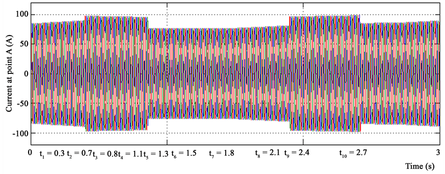
At  the ac voltage experiences a fall of 5 V. Intermediately, the major converter starts to insert spontaneous power demanding to balance this voltage fall. At the dc element, no significant modifies are experimental. The amplitude of current inserted in the system by the major converter amplifies as it can be experimental in Figure 14(a) and Figure 14(b). Figure 14(a) shows result for the existing approach. Figure 14(b) shows the performance for the proposed system. Because of the droop organization, modify of 5 V in the voltage will construct a dissimilarity of 12 kVA. At stable condition, the major converter would insert 12 kVA and the ac load would attract 3.2 kVA, consequently 8.8 kVA would be inserted to the major grid.
At  the second ac load is associated when the stable condition has not been attained yet. Both ac loads will attract 4.7 kW and 4.7 kVAr. At the primary direct element of the dynamic power is engaged from the grid because the tempo of difference of the power orientation at the major converter is restricted to guarantee the voltage constancy at the dc bus. In the dc bus, the PV module is producing 6.2 kW and the battery rate of charge is cheap to 1.5 kW to insert the remaining of the power (4.7 kW) to the ac part. Concerning the spontaneous power, the major converter inserts 12 kVA and the load attracts 4.7 kVA, thus the additional spontaneous power 6.3 kVA, is inserted into the network.
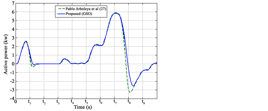
Figure 4. Active power at the ac part of the system (kW) for grid.

Figure 5. Active power at the ac part of the system (kW) for AC load.
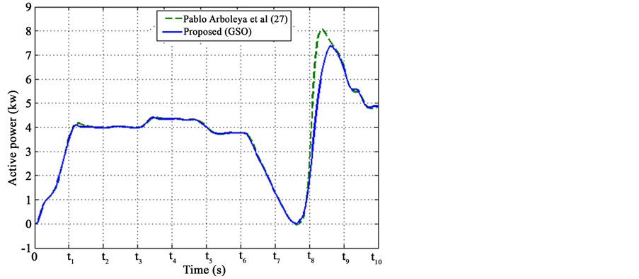
Figure 6. Active power at the ac part of the system (kW) for main converter.

Figure 7. Reactive power at the ac part of the system (kVA) for main convertor.

Figure 8. Reactive power at the ac part of the system (kVA) for grid.
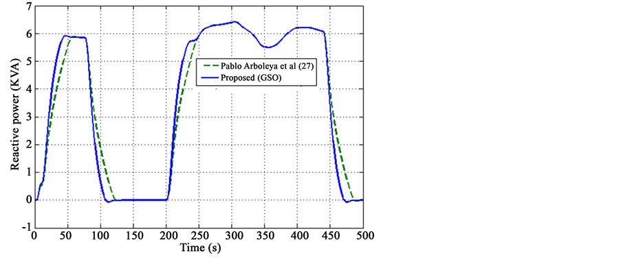
Figure 9. Reactive power at the ac part of the system (kVA) for main convertor.

Figure 10. Active power at the dc part of the system (kW) for PV.

Figure 11. Active power at the dc part of the system (kW) for LiBattery.
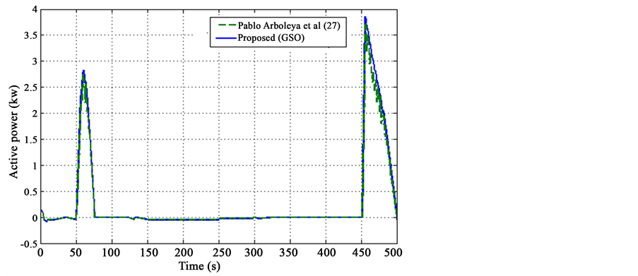
Figure 12. Active power at the dc part of the system (kW) for VLR.
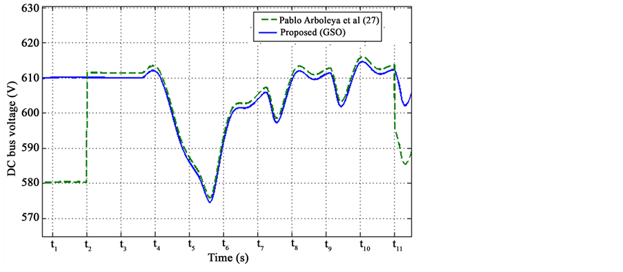
Figure 13. DC bus voltage (V).
 (a)
(a) (b)
(b)
Figure 14. Comparative analysis. current at point A (See Figure 1), during the study interval. ABC injected in the ac system by the main converter (at point B), (a) Existing (Pablo Arboleya et al. [19] ); (b) GSO based proposed tuning method.
At , the dc load is associated once more, now the power balance is the subsequently; the PV panel is creating 6.2 kW, the ac load attracts 4.7 kW and the dc load would attract 5.9 kW. Essentially the dc load absorbs a lesser quantity of power through the initial immediate imitative from the voltage fall origin by power disturb at the time of the dc load association. The battery will modify its working manner, and will begin functioning in release approach with a rate of release of 4.5 kW the additional power inserted at the dc bus is used to amplify the dc bus voltage.
At , the ac voltage is amplified in 5 V. At this voltage, the ac load will get through 5 kW that will be offered by the major converter as the
  is still zero. Because of the droop rule, the major converter will attempt to decrease the grid voltage fascinating and specified amount of spontaneous power resolute by the charge of the droop (in this case 12 kVA). The grid will give the spontaneous power (5 kVA inspired by the load at this voltage stage) plus the 12 kVA inspired by the major converter. The entire amount of spontaneous power introduced from the grid is about 17 kVA. There are no important alters in the dc bus (at t6 the voltage is almost in its charged value 600 V).
At  the dynamic power orientation at the top represented as “A” is put to
  which means, that the building must introduce 2 kW from the network. The load attracts 5 kW, 3 kW from the major converter and 2 kW from the grid. The dc bus voltage is close to the charged value thus the dc load is fascinating approximately 6 kW. The PV is inserting 6.4 kW and the major converter is relocating 3 kW to the ac element. In this situation, the battery must supply most of the power relocated from the dc subsystem to the ac one.
At , the dynamic power orientation at A is put to
 . In this study, the building is fascinating 6 kW from the major grid, but the load is only overwhelming 5 kW, so the major converter must relocate 1 kW from the ac element to the dc element. As the PV production and the dc load are almost impartial, the additional power relocated from the ac element is used to charge the battery.
At , the dynamic power orientation at A is put to
 , and the entire building will be active as a generator. The major converter must provide 5 kW insisted by the load plus 3 kW that must be inserted into the network being the entire amount of dynamic power 8 kW. The majority of this power must be given by the battery which means, at the initial immediate, there is a significant voltage fall at the dc because of the boundaries of the battery orientations rate of alter.
At , the dynamic power orientation at A is put to
 , and the dc voltage is once more close to the charged value. At the similar time the ac voltage experiences a fall of 12 V (from 405 to 393 V) so the major converter will become once more a spontaneous power generator, delivering the load needs plus a grid insertion of 10 kVA. Concerning the dynamic power, the major converter will insert 5.5 kW to the ac element. 1 kW is inserted into the grid and 4.5 kW are inspired by the load.
At , the dynamic power orientation at A is put to
  once more, so the building will be undetectable for the grid in terms of dynamic power utilization. The grid voltage is put to 400 V, so no spontaneous power insertion will be necessary from the major converter and the dc load will be switched off. The PV production will be 6.4 kW and the ac require of 4.7 kW so the additional power will be used to blame the battery. At the primary instant after the dc load detachment, the dc voltage will increase once more because of the battery orientation boundaries and the VLR will be triggered to bind the voltage increase to its utmost preset value of 620 V. Overall, the GSO based tuning method is achieved better performance than the Pablo Arboleya et al. [19] (existing) method.
5. Conclusion
Traditionally tuned PID controllers are employed to address the load frequency control (LFC) issues using various tuning methods in recent times. On the other hand, improperly tuned PID controller may exhibit poor dynamical response; in addition, wrong choice of integral gain may even destabilize the overall system. Conventional tuning is particular suited for simple systems, however fine-tuned heuristics based methods are particularly suited for complex systems e.g. power systems. In this article, we have developed an optimization technique to tune the PI parameters for building integration in smart micro-grids (MGs) with zero grid-impact. The necessity for such method has shown to be addressed when the entire PI controller need to be tuned to improve the MG efficiency. For that, we presented the proposed GSO based algorithm with suitable solution or member representation, derivation of fitness function, producer operation, scrounger operation and ranger operation. A complete and versatile model in MATLAB/SIMULINK was also presented. The simulations results and the experimental test validation were included. This research proved that the proposed system is usefulness in Micro-Grid (MG) applications. The control design through hybrid algorithm for other heuristic algorithms and for other complex systems remains a topic for further future research.
Cite this paper
S. Bhagawath,S. Edward Rajan, (2016) Managing of Smart Micro-Grid Connected Scheme Using Group Search Optimization. Circuits and Systems,07,3095-3111. doi: 10.4236/cs.2016.710263
References
- 1. Yoon, J.H., Baldick, R. and Novoselac, A. (2014) Dynamic Demand Response Controller Based on Real-Time Retail Price for Residential Buildings. IEEE Transactions on Smart Grid, 5, 121-129.
http://dx.doi.org/10.1109/TSG.2013.2264970 - 2. Vivekananthan, C., Mishra, Y., Ledwich, G. and Li, F. (2014) Demand Response for Residential Appliances via Customer Reward Scheme. IEEE Transactions on Smart Grid, 5, 809-820.
http://dx.doi.org/10.1109/TSG.2014.2298514 - 3. Moradzadeh, B. and Tomsovic, K. (2013) Two-Stage Residential Energy Management Considering Network Operational Constraints. IEEE Transactions on Smart Grid, 4, 2339-2346.
http://dx.doi.org/10.1109/TSG.2013.2265313 - 4. Argiento, R., Faranda, R., Pievatolo, A. and Tironi, E. (2012) Distributed Interruptible Load Shedding and Micro- Generator Dispatching to Benefit System Operations. IEEE Transactions on Power Systems, 27, 840-848.
http://dx.doi.org/10.1109/TPWRS.2011.2173217 - 5. Jumpei, B., Shigeo, N., Satoshi, S., Shin-Ichi, K., Takenori, Y., Atsushi, D., et al. (2005) Fundamental Measurements of a Small Scale Micro Grid Model System. Proceedings of International Conference on Electrical Engineering, 6.
- 6. Kadurek, P., Cobben, J., Kling, W. and Ribeiro, P. (2014) Aiding Power System Support by Means of Voltage Control with Intelligent Distribution Substation. IEEE Transactions on Smart Grid, 5, 84-91.
http://dx.doi.org/10.1109/TSG.2013.2289372 - 7. He, S., Wu, Q.H. and Saunders, J.R. (2006) A Novel Group Search Optimizer Inspired by Animal Behavioral Ecology. IEEE Congress on Evolutionary Computation, CEC.
- 8. He, S., Wu, Q.H. and Saunders, J.R. (2009) Group Search Optimizer: An Optimization Algorithm Inspired by Animal Searching Behavior. IEEE Transactions on Evolutionary Computation, 13, 973-990.
http://dx.doi.org/10.1109/TEVC.2009.2011992 - 9. Shen, H., Zhu, Y. and Zou, Z. (2011) Group Search Optimizer Algorithm for Constrained Optimization. Springer, Berlin Heidelberg, 48-53.
- 10. Moradi-Dalvand, M., Mohammadi-Ivatloo, B., Najafi, A. and Rabiee, A. (2012) Continuous Quick Group Search Optimizer for Solving Non-Convex Economic Dispatch Problems. Electric Power Systems Research, 93, 93-105.
http://dx.doi.org/10.1016/j.epsr.2012.07.009 - 11. Teimourzadeh, S. and Zare, K. (2014) Application of Binary Group Search Optimization to Distribution Network Reconfiguration. Electrical Power & Energy Systems, 62, 461-468.
http://dx.doi.org/10.1016/j.ijepes.2014.04.064 - 12. Hagh, M.T., Teimourzadeh, S., Alipour, M. and Aliasghary, P. (2014) Improved Group Search Optimization Method for Solving CHPED in Large Power Systems. Energy Conversion and Management, 80, 446-456.
http://dx.doi.org/10.1016/j.enconman.2014.01.051 - 13. Chen, C., Duan, S., Cai, T., Liu, B. and Hu, G. (2011) Smart Energy Management System for Optimal Microgrid Economic Operation. IET Renewable Power Generation, 5, 258-267.
http://dx.doi.org/10.1049/iet-rpg.2010.0052 - 14. Conti, S., Nicolosi, R., Rizzo, S.A. and Zeineldin, H.H. (2012) Optimal Dispatching of Distributed Generators and Storage Systems for MV Islanded Microgrids. IEEE Transactions on Power Delivery, 27, 1243-1251.
http://dx.doi.org/10.1109/TPWRD.2012.2194514 - 15. Tan, K.T., Peng, X.Y., So, P.L., Chu, Y.C. and Chen, M.Z.Q. (2012) Centralized Control for Parallel Operation of Distributed Generation Inverters in Microgrids. IEEE Transactions on Smart Grid, 3, 1977-1987.
http://dx.doi.org/10.1109/TSG.2012.2205952 - 16. Chen, S.X., Gooi, H.B. and Wang, M.Q. (2012) Sizing of Energy Storage for Micro-Grids. IEEE Transactions on Smart Grid, 3, 142-151.
http://dx.doi.org/10.1109/TSG.2011.2160745 - 17. Dasgupta, S., Mohan, S.N., Sahoo, S.K. and Panda, S.K. (2013) Lyapunov Function-Based Current Controller to Control Active and Reactive Power Flow from a Renewable Energy Source to a Generalized Three-Phase Microgrid System. IEEE Transactions on Industrial Electronics, 60, 799-813.
http://dx.doi.org/10.1109/TIE.2012.2206356 - 18. Mohammadi, M. and Nafar, M. (2013) Optimal Placement of Multi Types DG as Independent Private Sector under Pool/Hybrid Power Market Using GA-Based Tabu Search Method. International Journal of Electrical Power & Energy Systems, 51, 43-53.
http://dx.doi.org/10.1016/j.ijepes.2013.03.003 - 19. Arboleya, P., Gonzalez-Moran, C., Coto, M., Falvo, M.C., Martirano, L., Sbordone, D., Bertini, I. and Di Pietra, B. (2015) Efficient Energy Management in Smart Micro-Grids: Zero Grid Impact Buildings. IEEE Transactions on Smart Grid, 6, 1055-1063.
http://dx.doi.org/10.1109/tsg.2015.2392071 - 20. Al-Saedi, W., Lachowicz, S.W., Habibi, D. and Bass, O. (2013) Power Flow Control in Grid-Connected Microgrid Operation Using Particle Swarm Optimization under Variable load Conditions. International Journal of Electrical Power & Energy Systems, 49, 76-85.
http://dx.doi.org/10.1016/j.ijepes.2012.12.017 - 21. Gonzalez-Moran, C., Arboleya, P., Reigosa, D., Diaz, G. and Gomez-Aleixandre, J. (2009) Improved Model of Photovoltaic Sources Considering Ambient Temperature and Solar Irradiation. 2009 IEEE PES/IAS Conference on Sustainable Alternative Energy (SAE), Valencia, 28-30 September 2009, 1-6.
http://dx.doi.org/10.1109/SAE.2009.5534859