 International Journal of Geosciences, 2012, 3, 918-929 http://dx.doi.org/10.4236/ijg.2012.325094 Published Online October 2012 (http://www.SciRP.org/journal/ijg) Reformulation of the Vening-Meinesz Moritz Inverse Problem of Isostasy for Isostatic Gravity Disturbances Robert Tenzer1, Mohammad Bagherbandi2,3 1National School of Surveying, University of Otago, Dunedin, New Zealand 2Division of Geodesy and Geoinformatics, Royal Institute of Technology (KTH), Stockholm, Sweden 3Department of Industrial Development, IT and Land Management, University of Gävle, Gävle, Sweden Email: robert.tenzer@otago.ac.nz, mohbag@kth.se Received July 30, 2012; revised August 31, 2012; accepted September 30, 2012 ABSTRACT The isostatic gravity anomalies have been traditionally used to solve the inverse problems of isostasy. Since gravity measurements are nowadays carried out together with GPS positioning, the utilization of gravity disturbances in various regional gravimetric applications becomes possible. In global studies, the gravity disturbances can be computed using global geopotential models which are currently available to a relatively high accuracy and resolution. In this study we facilitate the definition of the isostatic gravity disturbances in the Vening-Meinesz Moritz inverse problem of isostasy for finding the Moho depths. We further utilize uniform mathematical formalism in the gravimetric forward modelling based on methods for a spherical harmonic analysis and synthesis of gravity field. We then apply both mathematical procedures to determine globally the Moho depths using the isostatic gravity disturbances. The results of gravimetric inversion are finally compared with the global crustal seismic model CRUST2.0; the RMS fit of the gravimetric Moho model with CRUST2.0 is 5.3 km. This is considerably better than the RMS fit of 7.0 km obtained after using the isostatic gravity anomalies. Keywords: Crust; Gravity; Isostasy; Moho Interface; Spherical Harmonics 1. Introduction The functional models of solving the inverse problem of isostasy have been traditionally formulated by means of the isostatic gravity anomalies (cf. Heiskanen and Moritz [1], p. 133). According to these definitions the topog- raphic mass surplus and the ocean mass deficiency are compensated either by a variable crustal thickness or density. The isostatic equilibrium is described in terms of the isostatic gravity anomalies which should theoretically be equal zero, provided that the refined Bouguer gravity anomalies are isostatically fully rebalanced by the corre- sponding gravitational attraction of compensating masses. The Pratt-Hayford isostatic model is based on adopting a constant depth of compensation while considering a variable density contrast (Pratt [2], Hayford [3], Hayford and Bowie [4]). In the Airy-Heiskanen isostatic model a constant density contrast is assumed while a depth of compensation is variable (Airy [5], Heiskanen and Ven- ing Meinesz [6]). Both these classical isostatic models are based on a local compensation scheme. Vening-Meinesz [7] modified the Airy-Heiskanen theory of isostasy with applying the regional instead of local compensation. Moritz [8] utilized the Vening-Meinesz inverse problem of isostasy for finding the Moho depths. Sjöberg [9] fur- ther generalized this concept for finding the Moho depths and density contrast. Sjöberg and Bagherbandi [10] computed the Moho depths based on solving Moritz’s generalization of the Vening-Meinesz inverse problem of isostasy (VMM isostatic model). Bagherbandi and Sjö- berg [11] demonstrated that the VMM Moho depths bet- ter agree with the Moho data taken from the global crustal seismic model CRUST2.0 (Bassin et al. [12]) than those obtained based on solving the Airy-Heiskanen isostatic model. The results of regional and global studies have shown often existing significant disagreement between the isos- tatic and seismic Moho depths. Several different reasons explaining this misfit were proposed and also confirmed by numerical experiments. Kaban et al. [13], for instance, demonstrated that the isostatic compensation does not take place only within the Earth’s crust but essentially also within the lithospheric mantle. This finding was later confirmed by Kaban et al. [14] and Tenzer et al. [15,16]. Several authors argued that the isostatic balance is also partially affected by the changing rigidity, glacial iso- static adjustment, plate motion, ocean lithosphere cooling, and other geophysical processes. Moreover, large portion of the isostatic mass balance is attributed to variable li- C opyright © 2012 SciRes. IJG 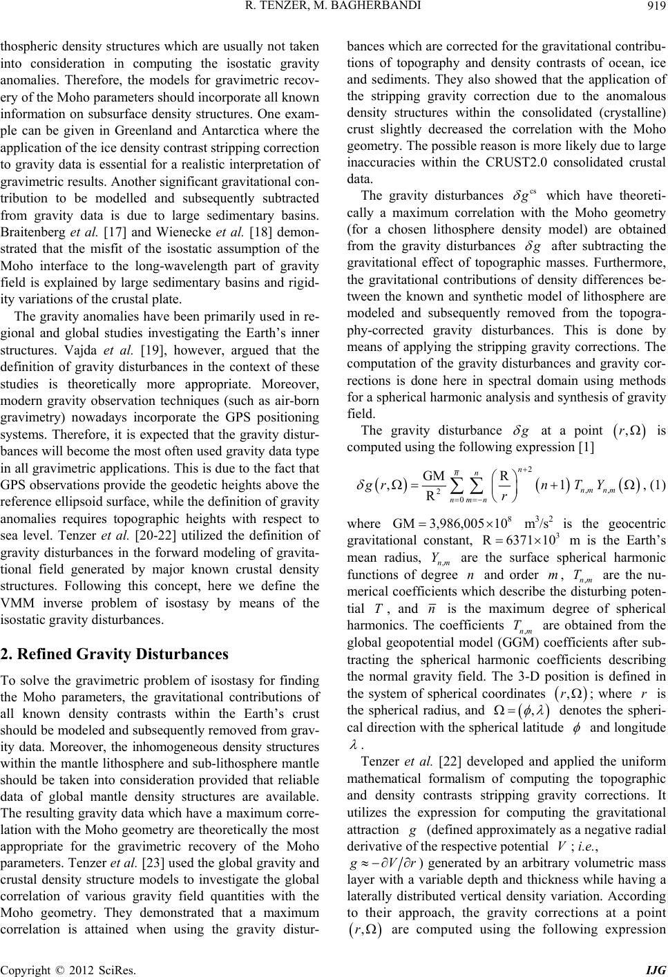 R. TENZER, M. BAGHERBANDI 919 thospheric density structures which are usually not taken into consideration in computing the isostatic gravity anomalies. Therefore, the models for gravimetric recov- ery of the Moho parameters should incorporate all known information on subsurface density structures. One exam- ple can be given in Greenland and Antarctica where the application of the ice density contrast stripping correction to gravity data is essential for a realistic interpretation of gravimetric results. Another significant gravitational con- tribution to be modelled and subsequently subtracted from gravity data is due to large sedimentary basins. Braitenberg et al. [17] and Wienecke et al. [18] demon- strated that the misfit of the isostatic assumption of the Moho interface to the long-wavelength part of gravity field is explained by large sedimentary basins and rigid- ity variations of the crustal plate. The gravity anomalies have been primarily used in re- gional and global studies investigating the Earth’s inner structures. Vajda et al. [19], however, argued that the definition of gravity disturbances in the context of these studies is theoretically more appropriate. Moreover, modern gravity observation techniques (such as air-born gravimetry) nowadays incorporate the GPS positioning systems. Therefore, it is expected that the gravity distur- bances will become the most often used gravity data type in all gravimetric applications. This is due to the fact that GPS observations provide the geodetic heights above the reference ellipsoid surface, while the definition of gravity anomalies requires topographic heights with respect to sea level. Tenzer et al. [20-22] utilized the definition of gravity disturbances in the forward modeling of gravita- tional field generated by major known crustal density structures. Following this concept, here we define the VMM inverse problem of isostasy by means of the isostatic gravity disturbances. 2. Refined Gravity Disturbances To solve the gravimetric problem of isostasy for finding the Moho parameters, the gravitational contributions of all known density contrasts within the Earth’s crust should be modeled and subsequently removed from grav- ity data. Moreover, the inhomogeneous density structures within the mantle lithosphere and sub-lithosphere mantle should be taken into consideration provided that reliable data of global mantle density structures are available. The resulting gravity data which have a maximum corre- lation with the Moho geometry are theoretically the most appropriate for the gravimetric recovery of the Moho parameters. Tenzer et al. [23] used the global gravity and crustal density structure models to investigate the global correlation of various gravity field quantities with the Moho geometry. They demonstrated that a maximum correlation is attained when using the gravity distur- bances which are corrected for the gravitational contribu- tions of topography and density contrasts of ocean, ice and sediments. They also showed that the application of the stripping gravity correction due to the anomalous density structures within the consolidated (crystalline) crust slightly decreased the correlation with the Moho geometry. The possible reason is more likely due to large inaccuracies within the CRUST2.0 consolidated crustal data. cs The gravity disturbances which have theoreti- cally a maximum correlation with the Moho geometry (for a chosen lithosphere density model) are obtained from the gravity disturbances after subtracting the gravitational effect of topographic masses. Furthermore, the gravitational contributions of density differences be- tween the known and synthetic model of lithosphere are modeled and subsequently removed from the topogra- phy-corrected gravity disturbances. This is done by means of applying the stripping gravity corrections. The computation of the gravity disturbances and gravity cor- rections is done here in spectral domain using methods for a spherical harmonic analysis and synthesis of gravity field. ,r at a point The gravity disturbance is computed using the following expression [1] 2 ,, 2 0 GM R ,1 R n nn nm nm nmn grnT Y r 8 GM3,986,005 10 3 R6371 10 nm T T , (1) where m 3/s2 is the geocentric gravitational constant, m is the Earth’s mean radius, ,nm Y are the surface spherical harmonic functions of degree and order , ,nm are the nu- merical coefficients which describe the disturbing poten- tial , and nT ,rr , is the maximum degree of spherical harmonics. The coefficients ,nm are obtained from the global geopotential model (GGM) coefficients after sub- tracting the spherical harmonic coefficients describing the normal gravity field. The 3-D position is defined in the system of spherical coordinates ; where is the spherical radius, and denotes the spheri- cal direction with the spherical latitude and longitude . Tenzer et al. [22] developed and applied the uniform mathematical formalism of computing the topographic and density contrasts stripping gravity corrections. It utilizes the expression for computing the gravitational attraction (defined approximately as a negative radial derivative of the respective potential ; i.e., V Vr ) generated by an arbitrary volumetric mass layer with a variable depth and thickness while having a laterally distributed vertical density variation. According to their approach, the gravity corrections at a point ,r are computed using the following expression Copyright © 2012 SciRes. IJG 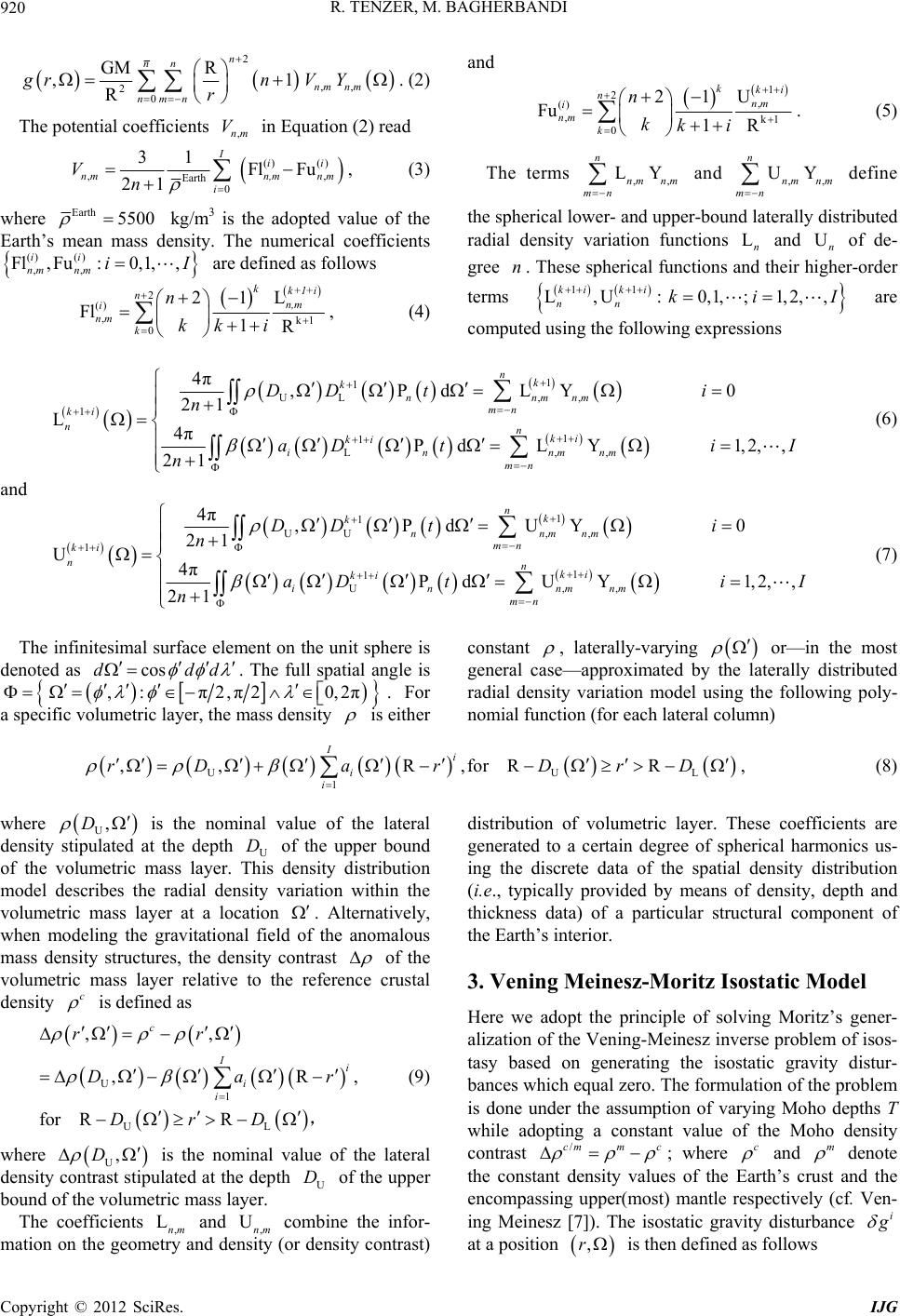 R. TENZER, M. BAGHERBANDI IJG 920 Copyright © 2012 SciRes. 2 2 0 GM R ,1 R n nn nmn gr n r and ,,nm nm V Y ,nm V . (2) The potential coefficients in Equation (2) read ()() , Fl Fu ii n,mn m , Earth 0 31 21 I n mi Vn , (3) where Earth 5500 0,1, ,iI kg/m3 is the adopted value of the Earth’s mean mass density. The numerical coefficients are defined as follows () () ,, Fl, Fu: ii nm nm 2 () , 0 Fl n i nm k n k k1 1 2L 1R kk+1+i n,m ki , (4) 1 2, () ,k1 0 U 1 2 Fu 1R kki nnm i nm k n kki ,, LY n nm nm mn ,, UY n nm nm mn nUn n . (5) The terms and define the spherical lower- and upper-bound laterally distributed radial density variation functions L and of de- gree . These spherical functions and their higher-order terms 11 L,U :0,1,;1,2,, ki ki nn kiI are computed using the following expressions 1 1 UL ,, 1 1 L,, 4π,PdLY 0 PdL Y1,2,, nk knnmnm mn nki ki innmnm mn DD ti aDti I 121 L4π 21 ki n n n (6) and 1 1 UU ,, 1 1 1 U,, 4π,PdUY 0 21 U4πPdUY1,2,, 21 nk knnmnm mn ki nnki ki innmnm mn DD ti n aDti I n cosdd d (7) The infinitesimal surface element on the unit sphere is denoted as . The full spatial angle is ,: π2, π20,2π . For a specific volumetric layer, the mass density is either constant , laterally-varying or—in the most general case—approximated by the laterally distributed radial density variation model using the following poly- nomial function (for each lateral column) UL D D U 1 ,,R,forR R Ii i i rDar Dr ,D , (8) where U is the nominal value of the lateral density stipulated at the depth U of the upper bound of the volumetric mass layer. This density distribution model describes the radial density variation within the volumetric mass layer at a location . Alternatively, when modeling the gravitational field of the anomalous mass density structures, the density contrast of the volumetric mass layer relative to the reference crustal density c is defined as U for R ,, R, c i rr ar D , ,D U D L /cmm c 1 UL , R I i i D Dr (9) where U is the nominal value of the lateral density contrast stipulated at the depth of the upper bound of the volumetric mass layer. The coefficients ,nm and , Unm combine the infor- mation on the geometry and density (or density contrast) distribution of volumetric layer. These coefficients are generated to a certain degree of spherical harmonics us- ing the discrete data of the spatial density distribution (i.e., typically provided by means of density, depth and thickness data) of a particular structural component of the Earth’s interior. 3. Vening Meinesz-Moritz Isostatic Model Here we adopt the principle of solving Moritz’s gener- alization of the Vening-Meinesz inverse problem of isos- tasy based on generating the isostatic gravity distur- bances which equal zero. The formulation of the problem is done under the assumption of varying Moho depths T while adopting a constant value of the Moho density contrast c ; where m and denote the constant density values of the Earth’s crust and the encompassing upper(most) mantle respectively (cf. Ven- ing Meinesz [7]). The isostatic gravity disturbance i at a position ,r is then defined as follows 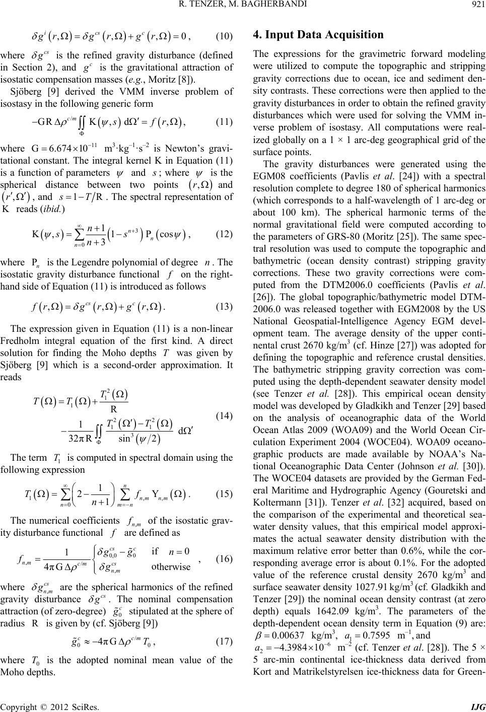 R. TENZER, M. BAGHERBANDI 921 ,, ics grg r cs ,0 c gr , (10) where is the refined gravity disturbance (defined in Section 2), and c is the gravitational attraction of isostatic compensation masses (e.g., Moritz [8]). Sjöberg [9] derived the VMM inverse problem of isostasy in the following generic form / GRK , d cm 11 ,sfr 6.674 10 , (11) where m 3·kg–1·s–2 is Newton’s gravi- tational constant. The integral kernel K in Equation (11) is a function of parameters G and ; where is the spherical distance between two points ,r and , and ,r 1RsT. The spectral representation of reads (ibid.) K 3Pcos n s 0 1 K, 1 3 n n n s n Pn , (12) where n is the Legendre polynomial of degree . The isostatic gravity disturbance functional on the right- hand side of Equation (11) is introduced as follows ,, cs frg r , c g r T . (13) The expression given in Equation (11) is a non-linear Fredholm integral equation of the first kind. A direct solution for finding the Moho depths was given by Sjöberg [9] which is a second-order approximation. It reads 2 1 1 3 R 1 32 πRsin T TT 22 11 d 2 TT T (14) The term 1 is computed in spectral domain using the following expression ,, Y nm nm n Tf 1 0 1 2 1 n nm n . (15) The numerical coefficients ,nm of the isostatic grav- ity disturbance functional are defined as 0,0 0 ,/ , 1 4πG cs c nm cs cm nm gg fg if 0 otherwise n cs , (16) where , nm cs are the spherical harmonics of the refined gravity disturbance . The nominal compensation attraction (of zero-degree) 0 c / 00 4πG ccm stipulated at the sphere of radius is given by (cf. Sjöberg [9]) R T T 0.00637 , (17) where 0 is the adopted nominal mean value of the Moho depths. 4. Input Data Acquisition The expressions for the gravimetric forward modeling were utilized to compute the topographic and stripping gravity corrections due to ocean, ice and sediment den- sity contrasts. These corrections were then applied to the gravity disturbances in order to obtain the refined gravity disturbances which were used for solving the VMM in- verse problem of isostasy. All computations were real- ized globally on a 1 × 1 arc-deg geographical grid of the surface points. The gravity disturbances were generated using the EGM08 coefficients (Pavlis et al. [24]) with a spectral resolution complete to degree 180 of spherical harmonics (which corresponds to a half-wavelength of 1 arc-deg or about 100 km). The spherical harmonic terms of the normal gravitational field were computed according to the parameters of GRS-80 (Moritz [25]). The same spec- tral resolution was used to compute the topographic and bathymetric (ocean density contrast) stripping gravity corrections. These two gravity corrections were com- puted from the DTM2006.0 coefficients (Pavlis et al. [26]). The global topographic/bathymetric model DTM- 2006.0 was released together with EGM2008 by the US National Geospatial-Intelligence Agency EGM devel- opment team. The average density of the upper conti- nental crust 2670 kg/m3 (cf. Hinze [27]) was adopted for defining the topographic and reference crustal densities. The bathymetric stripping gravity correction was com- puted using the depth-dependent seawater density model (see Tenzer et al. [28]). This empirical ocean density model was developed by Gladkikh and Tenzer [29] based on the analysis of oceanographic data of the World Ocean Atlas 2009 (WOA09) and the World Ocean Cir- culation Experiment 2004 (WOCE04). WOA09 oceano- graphic products are made available by NOAA’s Na- tional Oceanographic Data Center (Johnson et al. [30]). The WOCE04 datasets are provided by the German Fed- eral Maritime and Hydrographic Agency (Gouretski and Koltermann [31]). Tenzer et al. [32] acquired, based on the comparison of the experimental and theoretical sea- water density values, that this empirical model approxi- mates the actual seawater density distribution with the maximum relative error better than 0.6%, while the cor- responding average error is about 0.1%. For the adopted value of the reference crustal density 2670 kg/m3 and surface seawater density 1027.91 kg/m3 (cf. Gladkikh and Tenzer [29]) the nominal ocean density contrast (at zero depth) equals 1642.09 kg/m3. The parameters of the depth-dependent ocean density term in Equation (9) are: kg/m3, 10.7595a m –1, and 2 6 4.3984 10a m –2 (cf. Tenzer et al. [28]). The 5 × 5 arc-min continental ice-thickness data derived from Kort and Matrikelstyrelsen ice-thickness data for Green- Copyright © 2012 SciRes. IJG  R. TENZER, M. BAGHERBANDI Copyri IJG 922 land (Ekholm [33]) and from the updated ice-thickness data for Antarctica assembled by the BEDMAP project were used to generate the coefficients of the global ice-thickness model. These coefficients combined with the DTM2006.0 topographic coefficients were then used to compute the ice density contrast stripping gravity cor- rection with a spectral resolution up to degree/order 180. For the adopted values of the reference crustal density 2670 kg/m3 and the density of glacial ice 917 kg/m3 (cf. Cutnell and Kenneth [34]) the ice density contrast equals 1753 kg/m3. The 2 × 2 arc-deg CRUST2.0 data of the soft and hard sediment thickness and density were used to generate the coefficients of global sediment model with a spectral resolution complete to degree/order 90. This spectral resolution is compatible with a 2 × 2 arc-deg spatial resolution of CRUST2.0. The sediment density contrast was taken relative to the reference crus- tal density of 2670 kg/m3. The gravity disturbances computed on a 1 × 1 arc-deg surface grid are shown in Figure 1. They vary globally between −303 and 293 mGal, with a mean of −1 mGal and a standard deviation is 29 mGal. The topographic correction is shown in Figure 2. It varies globally within −696 and 9 mGal, with a mean of −70 mGal and a stan- dard deviation is 102 mGal. The values of the bathymet- ric stripping gravity correction are shown in Figure 3. This correction is everywhere positive and varies within 119 and 750 mGal, with a mean of 333 mGal and a stan- dard deviation is 165 mGal. The ice density contrast stripping gravity correction is shown in Figure 4. It var- ies within –3 and 175 mGal, with a mean of 11 mGal and a standard deviation is 29 mGal. The sediment density Figure 1. The gravity disturbance s computed globally on a 1 × 1 arc-deg surface grid using the EGM08 coefficients complete to degree 180 of spherical harmonics. Values are in mGal. Figure 2. The topographic gravity correction computed globally on a 1 × 1 arc-deg surface grid using the DTM2006.0 coefficients complete to degree/order 180. Values are in mGal. ght © 2012 SciRes. 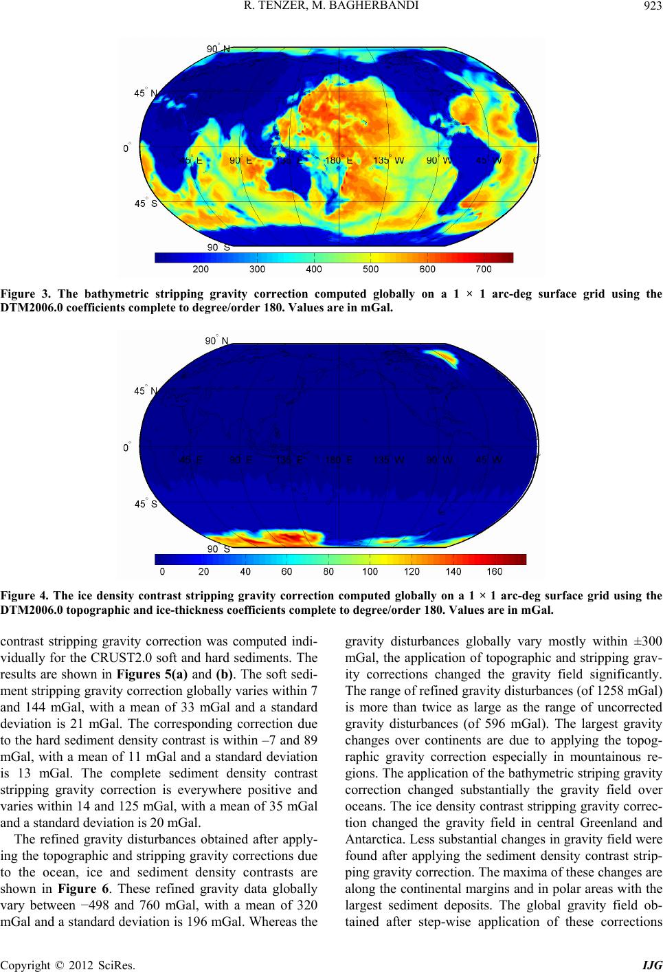 R. TENZER, M. BAGHERBANDI 923 Figure 3. The bathymetric stripping gravity correction computed globally on a 1 × 1 arc-deg surface grid using the DTM2006.0 coefficien ts complete to degree/order 180. Values are in mGal. Figure 4. The ice density contrast stripping gravity correction computed globally on a 1 × 1 arc-deg surface grid using the DTM2006.0 topographic and ice-thickness coefficients complete to degree/order 180. Values are in mGal. contrast stripping gravity correction was computed indi- vidually for the CRUST2.0 soft and hard sediments. The results are shown in Figures 5(a) and (b). The soft sedi- ment stripping gravity correction globally varies within 7 and 144 mGal, with a mean of 33 mGal and a standard deviation is 21 mGal. The corresponding correction due to the hard sediment density contrast is within –7 and 89 mGal, with a mean of 11 mGal and a standard deviation is 13 mGal. The complete sediment density contrast stripping gravity correction is everywhere positive and varies within 14 and 125 mGal, with a mean of 35 mGal and a standard deviation is 20 mGal. The refined gravity disturbances obtained after apply- ing the topographic and stripping gravity corrections due to the ocean, ice and sediment density contrasts are shown in Figure 6. These refined gravity data globally vary between −498 and 760 mGal, with a mean of 320 mGal and a standard deviation is 196 mGal. Whereas the gravity disturbances globally vary mostly within ±300 mGal, the application of topographic and stripping grav- ity corrections changed the gravity field significantly. The range of refined gravity disturbances (of 1258 mGal) is more than twice as large as the range of uncorrected gravity disturbances (of 596 mGal). The largest gravity changes over continents are due to applying the topog- raphic gravity correction especially in mountainous re- gions. The application of the bathymetric striping gravity correction changed substantially the gravity field over oceans. The ice density contrast stripping gravity correc- tion changed the gravity field in central Greenland and Antarctica. Less substantial changes in gravity field were found after applying the sediment density contrast strip- ping gravity correction. The maxima of these changes are along the continental margins and in polar areas with the largest sediment deposits. The global gravity field ob- tained after step-wise application of these corrections Copyright © 2012 SciRes. IJG  R. TENZER, M. BAGHERBANDI 924 (a) (b) Figure 5. The soft (a) and hard (b) sediments density contrast stripping gravity corrections computed globally on a 1 × 1 arc-deg surface grid using the coefficients of global sediment model complete to degree/order of 90 generated from the CRUST2.0 density and thickness data of soft and hard sediments. Values are in mGal. Figure 6. The refined gravity disturbances obtained after applying the topographic and stripping gravity corrections due to the ocean, ice and sediment density contrasts. The gravity data were computed on a 1 × 1 arc-deg grid of surface points. Values are in mGal. Copyright © 2012 SciRes. IJG 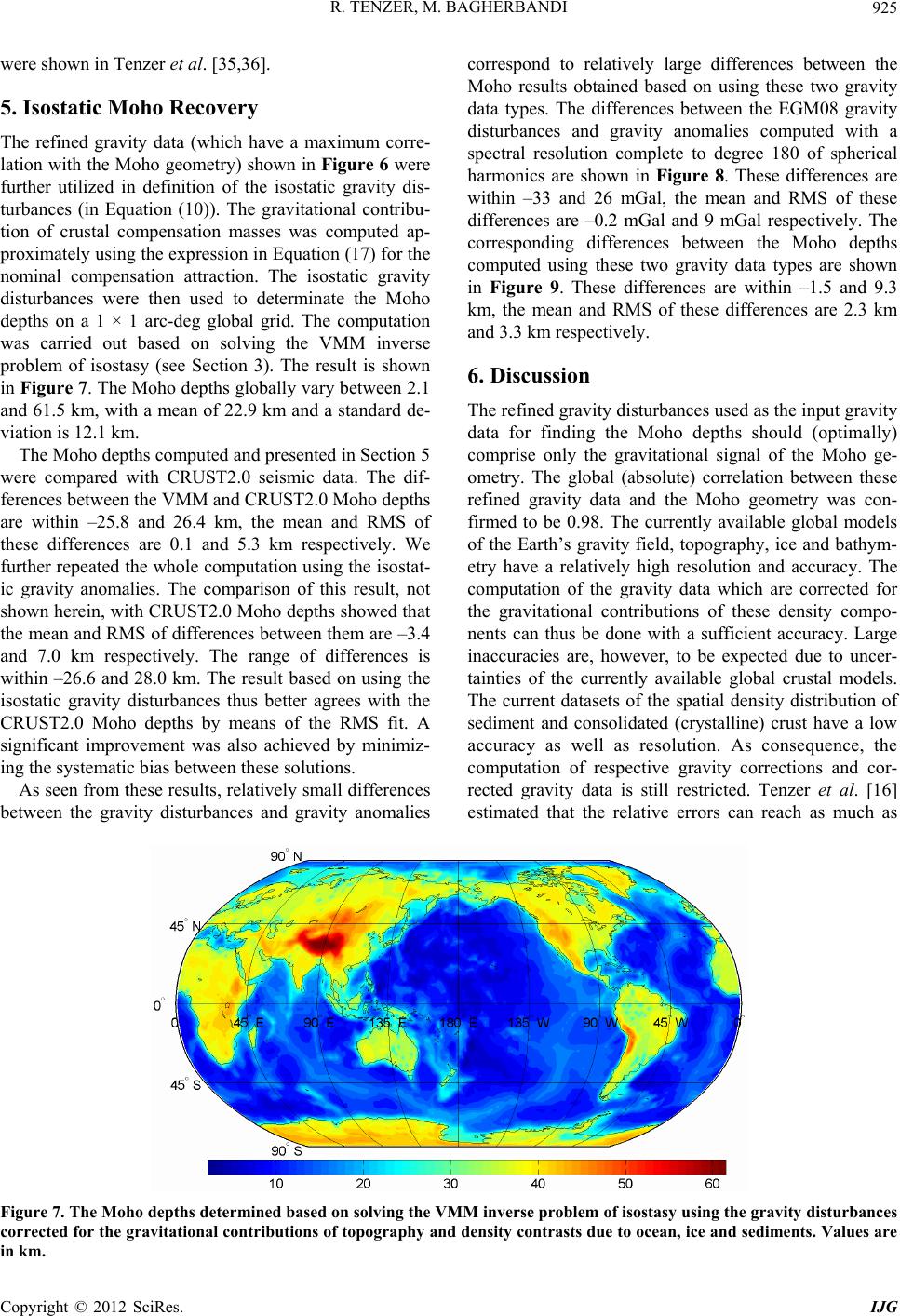 R. TENZER, M. BAGHERBANDI 925 were shown in Tenzer et al. [35,36]. 5. Isostatic Moho Recovery The refined gravity data (which have a maximum corre- lation with the Moho geometry) shown in Figure 6 were further utilized in definition of the isostatic gravity dis- turbances (in Equation (10)). The gravitational contribu- tion of crustal compensation masses was computed ap- proximately using the expression in Equation (17) for the nominal compensation attraction. The isostatic gravity disturbances were then used to determinate the Moho depths on a 1 × 1 arc-deg global grid. The computation was carried out based on solving the VMM inverse problem of isostasy (see Section 3). The result is shown in Figure 7. The Moho depths globally vary between 2.1 and 61.5 km, with a mean of 22.9 km and a standard de- viation is 12.1 km. The Moho depths computed and presented in Section 5 were compared with CRUST2.0 seismic data. The dif- ferences between the VMM and CRUST2.0 Moho depths are within –25.8 and 26.4 km, the mean and RMS of these differences are 0.1 and 5.3 km respectively. We further repeated the whole computation using the isostat- ic gravity anomalies. The comparison of this result, not shown herein, with CRUST2.0 Moho depths showed that the mean and RMS of differences between them are –3.4 and 7.0 km respectively. The range of differences is within –26.6 and 28.0 km. The result based on using the isostatic gravity disturbances thus better agrees with the CRUST2.0 Moho depths by means of the RMS fit. A significant improvement was also achieved by minimiz- ing the systematic bias between these solutions. As seen from these results, relatively small differences between the gravity disturbances and gravity anomalies correspond to relatively large differences between the Moho results obtained based on using these two gravity data types. The differences between the EGM08 gravity disturbances and gravity anomalies computed with a spectral resolution complete to degree 180 of spherical harmonics are shown in Figure 8. These differences are within –33 and 26 mGal, the mean and RMS of these differences are –0.2 mGal and 9 mGal respectively. The corresponding differences between the Moho depths computed using these two gravity data types are shown in Figure 9. These differences are within –1.5 and 9.3 km, the mean and RMS of these differences are 2.3 km and 3.3 km respectively. 6. Discussion The refined gravity disturbances used as the input gravity data for finding the Moho depths should (optimally) comprise only the gravitational signal of the Moho ge- ometry. The global (absolute) correlation between these refined gravity data and the Moho geometry was con- firmed to be 0.98. The currently available global models of the Earth’s gravity field, topography, ice and bathym- etry have a relatively high resolution and accuracy. The computation of the gravity data which are corrected for the gravitational contributions of these density compo- nents can thus be done with a sufficient accuracy. Large inaccuracies are, however, to be expected due to uncer- tainties of the currently available global crustal models. The current datasets of the spatial density distribution of sediment and consolidated (crystalline) crust have a low accuracy as well as resolution. As consequence, the computation of respective gravity corrections and cor- rected gravity data is still restricted. Tenzer et al. [16] estimated that the relative errors can reach as much as Figure 7. The Moho depths dete rmined based on solving the V MM inverse problem of isostasy using the gravity distur bances corrected for the gravitational contributions of topography and density contrasts due to ocean, ice and se diments. Values are in km. Copyright © 2012 SciRes. IJG 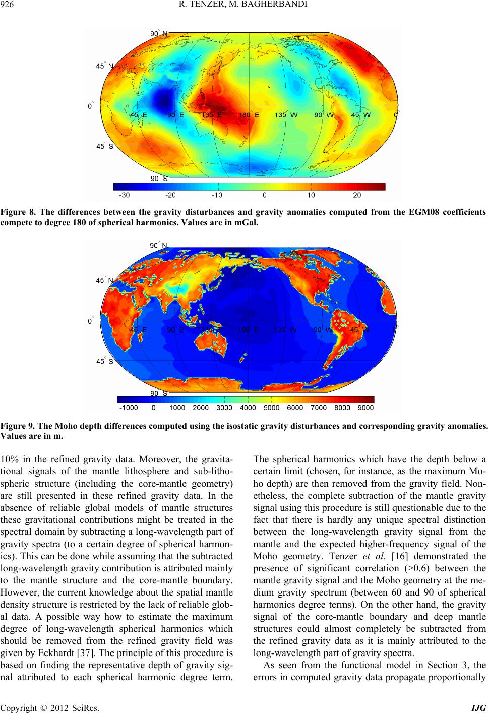 R. TENZER, M. BAGHERBANDI 926 Figure 8. The differences between the gravity disturbances and gravity anomalies computed from the EGM08 coefficients compete to degree 180 of spherical harmonics. Values are in m Gal . Figure 9. The Moho depth differences computed using the isostatic gravity disturbances and corresponding gravity anomalies. Values are in m. 10% in the refined gravity data. Moreover, the gravita- tional signals of the mantle lithosphere and sub-litho- spheric structure (including the core-mantle geometry) are still presented in these refined gravity data. In the absence of reliable global models of mantle structures these gravitational contributions might be treated in the spectral domain by subtracting a long-wavelength part of gravity spectra (to a certain degree of spherical harmon- ics). This can be done while assuming that the subtracted long-wavelength gravity contribution is attributed mainly to the mantle structure and the core-mantle boundary. However, the current knowledge about the spatial mantle density structure is restricted by the lack of reliable glob- al data. A possible way how to estimate the maximum degree of long-wavelength spherical harmonics which should be removed from the refined gravity field was given by Eckhardt [37]. The principle of this procedure is based on finding the representative depth of gravity sig- nal attributed to each spherical harmonic degree term. The spherical harmonics which have the depth below a certain limit (chosen, for instance, as the maximum Mo- ho depth) are then removed from the gravity field. Non- etheless, the complete subtraction of the mantle gravity signal using this procedure is still questionable due to the fact that there is hardly any unique spectral distinction between the long-wavelength gravity signal from the mantle and the expected higher-frequency signal of the Moho geometry. Tenzer et al. [16] demonstrated the presence of significant correlation (>0.6) between the mantle gravity signal and the Moho geometry at the me- dium gravity spectrum (between 60 and 90 of spherical harmonics degree terms). On the other hand, the gravity signal of the core-mantle boundary and deep mantle structures could almost completely be subtracted from the refined gravity data as it is mainly attributed to the long-wavelength part of gravity spectra. As seen from the functional model in Section 3, the errors in computed gravity data propagate proportionally Copyright © 2012 SciRes. IJG 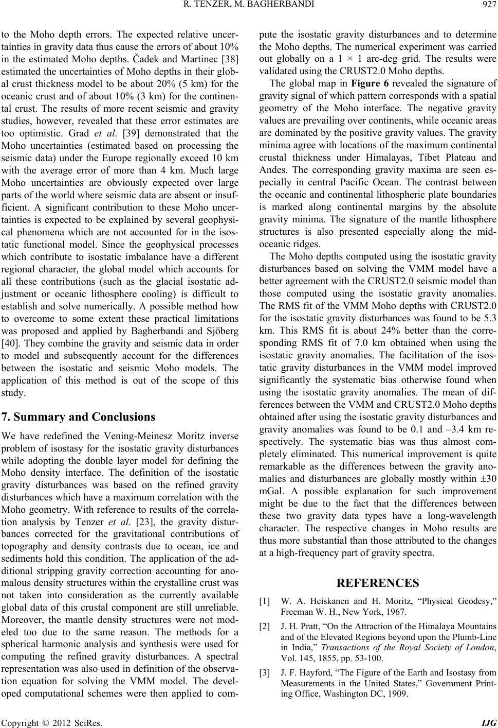 R. TENZER, M. BAGHERBANDI 927 to the Moho depth errors. The expected relative uncer- tainties in gravity data thus cause the errors of about 10% in the estimated Moho depths. Čadek and Martinec [38] estimated the uncertainties of Moho depths in their glob- al crust thickness model to be about 20% (5 km) for the oceanic crust and of about 10% (3 km) for the continen- tal crust. The results of more recent seismic and gravity studies, however, revealed that these error estimates are too optimistic. Grad et al. [39] demonstrated that the Moho uncertainties (estimated based on processing the seismic data) under the Europe regionally exceed 10 km with the average error of more than 4 km. Much large Moho uncertainties are obviously expected over large parts of the world where seismic data are absent or insuf- ficient. A significant contribution to these Moho uncer- tainties is expected to be explained by several geophysi- cal phenomena which are not accounted for in the isos- tatic functional model. Since the geophysical processes which contribute to isostatic imbalance have a different regional character, the global model which accounts for all these contributions (such as the glacial isostatic ad- justment or oceanic lithosphere cooling) is difficult to establish and solve numerically. A possible method how to overcome to some extent these practical limitations was proposed and applied by Bagherbandi and Sjöberg [40]. They combine the gravity and seismic data in order to model and subsequently account for the differences between the isostatic and seismic Moho models. The application of this method is out of the scope of this study. 7. Summary and Conclusions We have redefined the Vening-Meinesz Moritz inverse problem of isostasy for the isostatic gravity disturbances while adopting the double layer model for defining the Moho density interface. The definition of the isostatic gravity disturbances was based on the refined gravity disturbances which have a maximum correlation with the Moho geometry. With reference to results of the correla- tion analysis by Tenzer et al. [23], the gravity distur- bances corrected for the gravitational contributions of topography and density contrasts due to ocean, ice and sediments hold this condition. The application of the ad- ditional stripping gravity correction accounting for ano- malous density structures within the crystalline crust was not taken into consideration as the currently available global data of this crustal component are still unreliable. Moreover, the mantle density structures were not mod- eled too due to the same reason. The methods for a spherical harmonic analysis and synthesis were used for computing the refined gravity disturbances. A spectral representation was also used in definition of the observa- tion equation for solving the VMM model. The devel- oped computational schemes were then applied to com- pute the isostatic gravity disturbances and to determine the Moho depths. The numerical experiment was carried out globally on a 1 × 1 arc-deg grid. The results were validated using the CRUST2.0 Moho depths. The global map in Figure 6 revealed the signature of gravity signal of which pattern corresponds with a spatial geometry of the Moho interface. The negative gravity values are prevailing over continents, while oceanic areas are dominated by the positive gravity values. The gravity minima agree with locations of the maximum continental crustal thickness under Himalayas, Tibet Plateau and Andes. The corresponding gravity maxima are seen es- pecially in central Pacific Ocean. The contrast between the oceanic and continental lithospheric plate boundaries is marked along continental margins by the absolute gravity minima. The signature of the mantle lithosphere structures is also presented especially along the mid- oceanic ridges. The Moho depths computed using the isostatic gravity disturbances based on solving the VMM model have a better agreement with the CRUST2.0 seismic model than those computed using the isostatic gravity anomalies. The RMS fit of the VMM Moho depths with CRUST2.0 for the isostatic gravity disturbances was found to be 5.3 km. This RMS fit is about 24% better than the corre- sponding RMS fit of 7.0 km obtained when using the isostatic gravity anomalies. The facilitation of the isos- tatic gravity disturbances in the VMM model improved significantly the systematic bias otherwise found when using the isostatic gravity anomalies. The mean of dif- ferences between the VMM and CRUST2.0 Moho depths obtained after using the isostatic gravity disturbances and gravity anomalies was found to be 0.1 and –3.4 km re- spectively. The systematic bias was thus almost com- pletely eliminated. This numerical improvement is quite remarkable as the differences between the gravity ano- malies and disturbances are globally mostly within 30 mGal. A possible explanation for such improvement might be due to the fact that the differences between these two gravity data types have a long-wavelength character. The respective changes in Moho results are thus more substantial than those attributed to the changes at a high-frequency part of gravity spectra. REFERENCES [1] W. A. Heiskanen and H. Moritz, “Physical Geodesy,” Freeman W. H., New York, 1967. [2] J. H. Pratt, “On the Attraction of the Himalaya Mountains and of the Elevated Regions beyond upon the Plumb-Line in India,” Transactions of the Royal Society of London, Vol. 145, 1855, pp. 53-100. [3] J. F. Hayford, “The Figure of the Earth and Isostasy from Measurements in the United States,” Government Print- ing Office, Washington DC, 1909. Copyright © 2012 SciRes. IJG  R. TENZER, M. BAGHERBANDI 928 [4] J. F. Hayford and W. Bowie, “The Effect of Topography and Isostatic Compensation upon the Intensity of Grav- ity,” BiblioBazaar, Charleston, 1912. [5] G. B. Airy, “On the Computations of the Effect of the Attraction of the Mountain Masses as Disturbing the Ap- parent Astronomical Latitude of Stations in Geodetic Surveys,” Transactions of the Royal Society of London, Vol. 145, 1855, pp. 101-104. [6] W. A. Heiskanen and F. A. Vening Meinesz, “The Earth and Its Gravity Field,” McGraw-Hill Book Company Inc., New York, 1958. [7] F. A. Vening Meinesz, “Une Nouvelle Méthode Pour la Réduction Isostatique Régionale de l’Intensité de la Pe- santeur,” Bulletin Geodesique, Vol. 29, No. 1, 1931, pp. 33-51. doi:10.1007/BF03030038 [8] H. Moritz, “The Figure of the Earth,” Wichmann H., Karlsruhe, 1990. [9] L. E. Sjöberg, “Solving Vening Meinesz-Moritz Inverse Problem in Isostasy,” Geophysical Journal International, Vol. 179, No. 3, 2009, pp. 1527-1536. doi:10.1111/j.1365-246X.2009.04397.x [10] L. E. Sjöberg and M. Bagherbandi, “A Method of Esti- mating the Moho Density Contrast with A Tentative Ap- plication by EGM08 and CRUST2.0,” Acta Geophysica, Vol. 59, No. 3, 2011, pp. 502-525. doi:10.2478/s11600-011-0004-6 [11] M. Bagherbandi and L. E. Sjöberg, “Comparison of Crustal Thickness from Two Isostatic Models versus CRUST2.0,” Studia Geophysica et Geodartica, Vol. 55, No. 4, 2011, pp. 641-666. doi:10.1007/s11200-010-9030-0 [12] C. Bassin, G. Laske and T. G. Masters, “The Current Limits of Resolution for Surface Wave Tomography in North America,” EOS Transactions, American Geo- physical Union, Vol. 81, 2000. [13] M. K. Kaban, P. Schwintzer and S. A. Tikhotsky, “A Global Isostatic Gravity Model of the Earth,” Geophysi- cal Journal International, Vol. 136, No. 3, 1999, pp. 519- 536. doi:10.1046/j.1365-246x.1999.00731.x [14] M. K. Kaban, P. Schwintzer and Ch. Reigber, “A New Isostatic Model of the Lithosphere and Gravity Field,” Journal of Geodesy, Vol. 78, No. 6, 2004, pp. 368-385. doi:10.1007/s00190-004-0401-6 [15] R. Tenzer, Hamayun and P. Vajda, “Global Maps of the CRUST2.0 Crustal Components Stripped Gravity Distur- bances,” Journal of Geophysical Research, Vol. 114, No. B5, 2009, pp. 281-297. [16] R. Tenzer, V. Gladkikh, P. Vajda and P. Novák, “Spatial and Spectral Analysis of Refined Gravity Data for Mod- elling the Crust-Mantle Interface and Mantle-Lithosphere Structure,” Surveys in Geophysics, Vol. 33, No. 5, 2012, pp. 817-839. doi:10.1007/s10712-012-9173-3 [17] C. Braitenberg, S. Wienecke and Y. Wang, “Basement Structures from Satellite-Derived Gravity Field: South China Sea ridge,” Journal of Geophysical Research, Vol. 111, 2006, Article ID: B05407. doi:10.1029/2005JB003938 [18] S. Wienecke, C. Braitenberg and H.-J. Götze, “A New Analytical Solution Estimating the Flexural Rigidity in the Central Andes,” Geophysical Journal International, Vol. 169, No. 3, 2007, pp. 789-794. doi:10.1111/j.1365-246X.2007.03396.x [19] P. Vajda, P. Vaníček, P. Novák, R. Tenzer and A. Ell- mann, “Secondary Indirect Effects in Gravity Anomaly Data Inversion or Interpretation,” Journal of Geophysical Research, Vol. 112, 2007, Article ID: B06411. [20] R. Tenzer, P. Vajda and P. Hamayun, “A Mathematical Model of the Bathymetry-Generated External Gravita- tional Field,” Contributions to Geophysics and Geodesy, Vol. 40, No. 1, 2010, pp. 31-44. doi:10.2478/v10126-010-0002-8 [21] R. Tenzer, A. Abdalla, P. Vajda and P. Hamayun, “The Spherical Harmonic Representation of the Gravitational Field Quantities Generated by the Ice Density Contrast,” Contributions to Geophysics and Geodesy, Vol. 40, No. 3, 2010, pp. 207-223. doi:10.2478/v10126-010-0009-1 [22] R. Tenzer, P. Novák, P. Vajda, V. Gladkikh and P. Ha- mayun, “Spectral Harmonic Analysis and Synthesis of Earth’s Crust Gravity Field,” Computational Geosciences, Vol. 16, No. 1, 2012, pp. 193-207. doi:10.1007/s10596-011-9264-0 [23] R. Tenzer, Hamayun and P. Vajda, “A Global Correlation of the Step-Wise Consolidated Crust-Stripped Gravity Field Quantities with the Topography, Bathymetry, and the CRUST2.0 Moho Boundary,” Contributions to Geo- physics and Geodesy, Vol. 39, No. 2, 2009, pp. 133-147. doi:10.2478/v10126-009-0006-4 [24] N. K. Pavlis, S. A. Holmes, S. C. Kenyon and J. K. Factor, “The Development and Evaluation of the Earth Gravita- tional Model 2008 (EGM2008),” Journal of Geophysical Research, Vol. 117, 2012, Article ID: B04406. [25] H. Moritz, “Advanced Physical Geodesy,” Abacus Press, Tunbridge Wells, 1980. [26] N. K. Pavlis, J. K. Factor and S. A. Holmes, “Ter- rain-Related Gravimetric Quantities Computed for the Next EGM,” In: A. Kiliçoglu and R. Forsberg, Eds., Gravity Field of the Earth. Proceedings of the 1st Inter- national Symposium of the International Gravity Field Service, Harita Dergisi, No. 18, General Command of Mapping, Ankara, Turkey, 2007. [27] W. J. Hinze, “Bouguer Reduction Density, Why 2.67?” Geophysics, Vol. 68, No. 5, 2003, pp. 1559-1560. doi:10.1190/1.1620629 [28] R. Tenzer, P. Novák and V. Gladkikh, “The Bathymetric Stripping Corrections to Gravity Field Quantities for a Depth-Dependant Model of the Seawater Density,” Ma- rine Geodesy, Vol. 35, No. 2, 2012, pp. 198-220. doi:10.1080/01490419.2012.670592 [29] V. Gladkikh and R. Tenzer, “A Mathematical Model of the Global Ocean Saltwater Density Distribution,” Pure and Applied Geophysics, Vol. 169, No. 1-2, 2011, pp. 249-257. doi:10.1007/s00024-011-0275-5 [30] D. R. Johnson, H. E. Garcia and T. P. Boyer, “World Ocean Database 2009 Tutorial,” In: S. Levitus, Ed., NODC Internal Report 21, NOAA Printing Office, Silver Spring, 2009, 18 p. [31] V. V. Gouretski and K. P. Koltermann, “Berichte des Copyright © 2012 SciRes. IJG  R. TENZER, M. BAGHERBANDI Copyright © 2012 SciRes. IJG 929 Bundesamtes für Seeschifffahrt und Hydrographie,” Nr. 35, 2004. [32] R. Tenzer, P. Novák and V. Gladkikh, “On the Accuracy of the Bathymetry-Generated Gravitational Field Quanti- ties for a Depth-Dependent Seawater Density Distribu- tion,” Studia Geophysica et Geodaetica, Vol. 55, No. 4, 2011, pp. 609-626. doi:10.1007/s11200-010-0074-y [33] S. Ekholm, “A Full Coverage, High-Resolution, Topog- raphic Model of Greenland, Computed from a Variety of Digital Elevation Data,” Journal of Geophysical Research, Vol. B10, No. 21, 1996, pp. 961-972. [34] J. D. Cutnell and W. J. Kenneth, “Physics,” 3rd Edition, Wiley, New York, 1995. [35] R. Tenzer, Hamayun and P. Vajda, “Global Map of the Gravity Anomaly Corrected for Complete Effects of the Topography, and of Density Contrasts of Global Ocean, Ice, and Sediments,” Contributions to Geophysics and Geodesy, Vol. 38, No. 4, 2008, pp. 357-370. [36] R. Tenzer, Hamayun, P. Novák, V. Gladkikh and P. Va- jda, “Global Crust-Mantle Density Contrast Estimated from EGM2008, DTM2008, CRUST2.0, and ICE-5G,” Pure and Applied Geophysics, Vol. 169, No. 9, 2012, pp. 1663-1678. doi:10.1007/s00024-011-0410-3 [37] D. H. Eckhardt, “The Gains of Small Circular, Square and Rectangular Filters for Surface waves on a Sphere,” Journal of Geodesy Vol. 57, No. 1-4, 1983, pp. 394-409. doi:10.1007/BF02520942 [38] O. Čadek and Z. Martinec, “Spherical Harmonic Expan- sion of the Earth’s Crustal Thickness up to Degree and Order 30,” Studia Geophisica et Geodeatica, Vol. 35, No. 3, 1991, pp. 151-165. doi:10.1007/BF01614063 [39] M. Grad, T. Tiira and ESC Working Group, “The Moho Depth Map of the European Plate,” Geophysical Journal Internatioanl, Vol. 176, No. 1, 2009, pp. 279-292. doi:10.1111/j.1365-246X.2008.03919.x [40] M. Bagherbandi and L. E. Sjöberg, “Non-Isostatic Effects on Crustal Thickness: A Study Using CRUST2.0 in Fen- noscandia,” Physics of the Earth and Planetary Interiors, Vol. 200-201, 2012, pp. 37-44. doi:10.1016/j.pepi.2012.04.001
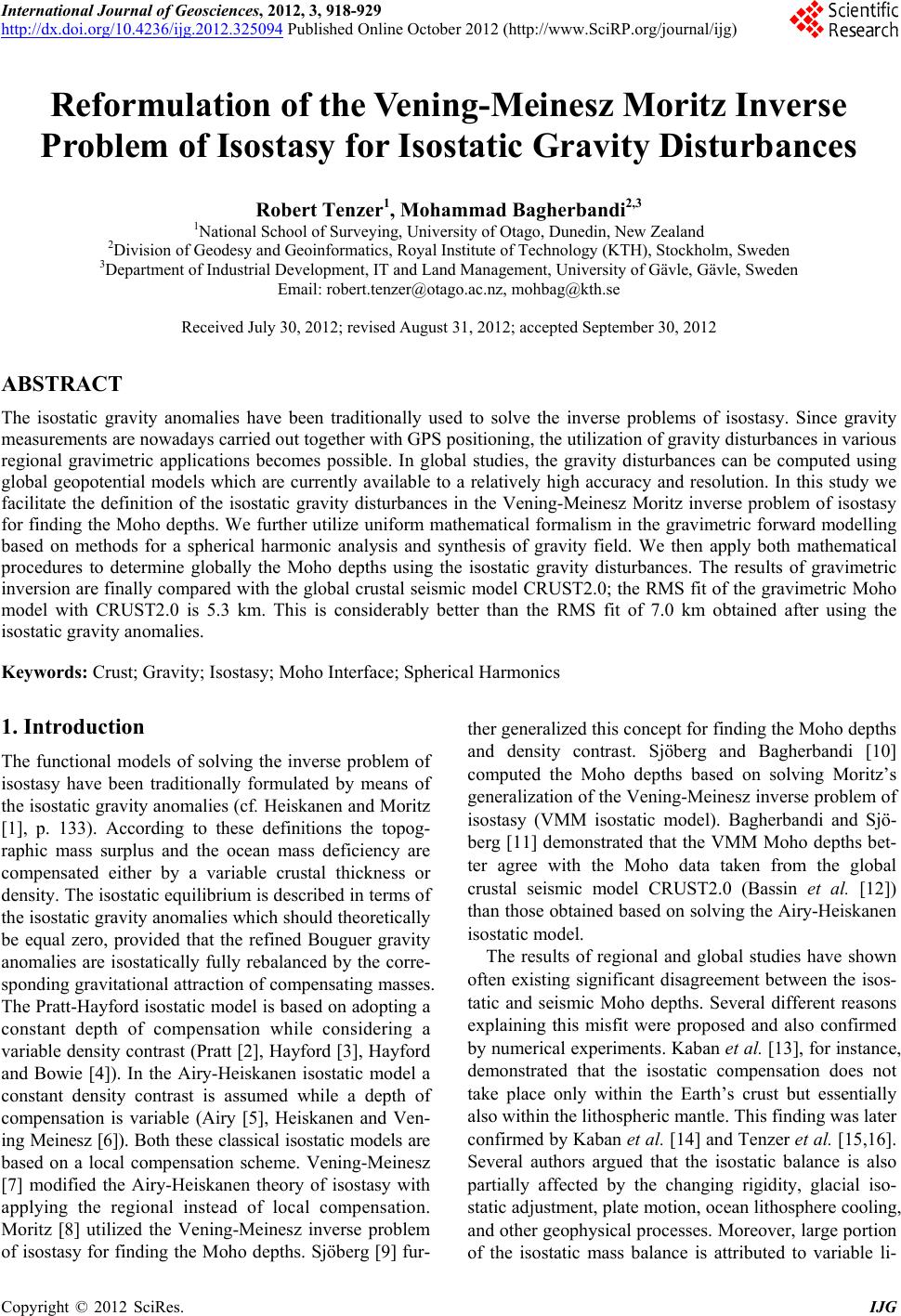
|