Paper Menu >>
Journal Menu >>
 Journal of Global Positioning Systems (2004) Vol. 3, No. 1-2: 2-11 GNSS Indoor Location Technologies Gérard Lachapelle Position, Location And Navigation Group, Department of Geomatics Engineering, University of Calgary, Canada Tel: 403 220 7104 E-mail: Lachapelle@geomatics.ucalgary.ca Received: 15 November 2004 / Accepted: 3 February 2005 Abstract. This paper presents an overview of GNSS- based indoor location technologies. Current and emerging users and their potential requirements are first discussed. Signal attenuation and multipath caused under indoor environments are described. The basic method to acquire and track attenuated signals, namely longer integration of signal measurements, is summarized. The need for assisted GPS is addressed. Availability and accuracy performance currently achievable under various conditions (wooden structure building, single family residence, large sport facility) are illustrated through selected test results. The limitations of current technologies and potential enhancements are discussed. These include measurement noise, existing signal structure and future enhancements, frequency and time errors, user motion, sensor aiding such as ultra-tight integration, and solution reliability and continuity. The paper concludes with a discussion of receiver testing standards. The possibility of using a GNSS hardware simulator to create reproducible indoor environments in order to overcome the controllability issue encountered with real environments is analysed. Key words: Indoor location, AGPS, HSGPS, aided GPS, Indoor GPS 1 Introduction The need for indoor location was initially spurred by the mid-90s U.S. FCC decision to require mobile phone service providers to locate emergency (E911) callers with an accuracy requirement (October 1999 revision) of 100 m (67%) or 300 m (95%) for network- based solutions and 50 m (67%) or 150 m (95%) for handset-based solutions, the latter being the case with the use of GPS. The most promising technologies to achieve this on a continental level were cellular phone network-based TDOA methods and GPS if the latter could be made to operate under attenuated signal conditions such as urban canyons, forested areas and indoors. Attenuated signal environments are now often simply labelled “indoor” environments for the sake of simplicity. Early developments and testing of cellular phone network-based TDOA methods resulted in promising results with the use of GPS to precisely time synchronize signal transmissions (e.g. Klukas et al 1997, 1998). However, the additional cell equipment required proved to be a challenge. In addition, TDOA being an hyperbolic location method (similar to Loran- C for instance), observability was found to be low in a urban environment given the rapidly changing geometry of the available cells. Outside of urban areas, the cell geometry was simply not present to meet availability requirements. In parallel to the above developments, experiments to increase the integration time to potentially allow GPS signal reception under attenuated signal environments yielded promising results, especially with the use of assisted methods (Petersen et al 1997, Moeglein & Krasner 1998, Garin et al 1999). Given the existing space-based infrastructure and coverage advantages of GPS that makes possible an in-mobile phone solution, R&D efforts on improving GPS performance intensified rapidly. It soon became obvious that continuous outdoor and indoor location availability could be used in a large number of applications such as personal digital assistant location, asset tracking, vehicular navigation, and no doubt many others to be discovered, in addition to emergency services. These applications now form part of a location-based services business that is expected to grow from USD 0.5 B in 2003 to USD 28 B in 2008. One of the most important technical questions arising is what are the performance levels users want. Standard location and navigation performance parameters are important, namely availability, accuracy, reliability and integrity, and 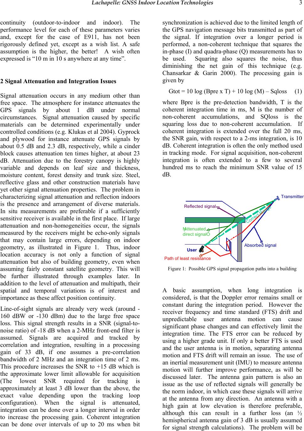 Lachapelle: GNSS Indoor Location Technologies 3 continuity (outdoor-to-indoor and indoor). The performance level for each of these parameters varies and, except for the case of E911, has not been rigorously defined yet, except as a wish list. A safe assumption is the higher, the better! A wish often expressed is “10 m in 10 s anywhere at any time”. 2 Signal Attenuation and Integration Issues Signal attenuation occurs in any medium other than free space. The atmosphere for instance attenuates the GPS signals by about 1 dB under normal circumstances. Signal attenuation caused by specific materials can be determined experimentally under controlled conditions (e.g. Klukas et al 2004). Gyprock and plywood for instance attenuate GPS signals by about 0.5 dB and 2.3 dB, respectively, while a cinder block causes attenuation ten times higher, at about 23 dB. Attenuation due to the forestry canopy is highly variable and depends on leaf size and thickness, moisture content, forest density and trunk size. Steel, reflective glass and other construction materials have yet other signal attenuation properties. The problem in characterizing signal attenuation and reflection indoors is the presence and arrangement of diverse materials. In situ measurements are preferable if a sufficiently sensitive receiver is available in the first place. If large attenuation and non-homogeneities occur, the signals measured by the receivers might be echo-only signals that may contain large errors, depending on indoor geometry, as illustrated in Figure 1. Thus, indoor location accuracy is not only a function of signal attenuation but also of building geometry, even when assuming fairly constant satellite geometry. This will be further illustrated through examples later. In addition to the level of attenuation and multipath, their spatial and temporal variations is of interest and importance as these affect position continuity. Line-of-sight signals are already very week (around - 160 dBW or -130 dBm) due to the large free space loss. This signal strength results in a SNR (signal-to- noise ratio) of -18 dB when a 2-MHz front-end filter is assumed. Signals are acquired and tracked by correlation and integration, resulting in a processing gain of 33 dB, if one assumes a pre-correlation bandwidth of 2 MHz and an integration time of 2 ms. This procedure increases the SNR to +15 dB which is the approximate lower limit allowable for acquisition (The lowest SNR required for tracking is approximately at least 3 dB lower than the above, the exact value depending upon the tracking loop configuration). When the signal is attenuated, integration can be done over a longer interval in order to increase the processing gain. Coherent integration can be done over intervals of up to 20 ms when bit synchronization is achieved due to the limited length of the GPS navigation message bits transmitted as part of the signal. If integration over a longer period is performed, a non-coherent technique that squares the in-phase (I) and quadra-phase (Q) measurements has to be used. Squaring also squares the noise, thus diminishing the net gain of this technique (e.g. Chansarkar & Garin 2000). The processing gain is given by Gtot = 10 log (Bpre x T) + 10 log (M) – Sqloss (1) where Bpre is the pre-detection bandwidth, T is the coherent integration time in ms, M is the number of non-coherent accumulations, and SQloss is the squaring loss due to non-coherent accumulation. If coherent integration is extended over the full 20 ms, the SNR gain, with respect to a 2-ms integration, is 10 dB. Coherent integration is often the only method used in tracking mode. For signal acquisition, non-coherent integration is often extended to a few to several hundred ms to reach the minimum SNR value of 15 dB. Transmitter Reflected signal ŅAttenuated direct signalÓ User Absorbed signal Correct Range Path of least resistance Figure 1: Possible GPS signal propagation paths into a building A basic assumption, when long integration is considered, is that the Doppler error remains small or constant during the integration period. However the receiver frequency and time standard (FTS) drift and unpredictable user antenna motion can cause significant phase changes and can effectively limit the integration time. The FTS error can be reduced by using a higher grade unit. If only a better FTS is used and the user antenna is in motion, separating antenna motion and FTS drift will remain an issue. The use of an inertial measurement unit (IMU) to measure antenna motion will further improve performance, as will be discussed later. The antenna gain pattern is also an issue as the use of reflected signals will generally be the norm indoor, in which case these signals will arrive at the antenna from any direction. An antenna with a high gain at low elevation is therefore preferable, although this can result in a further loss (an ½ hemispherical antenna gain of 3 dB is usually assumed for signal strength calculations). The problem will be 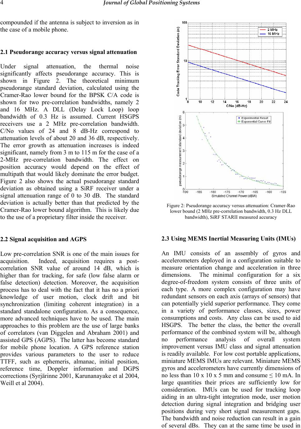 4 Journal of Global Positioning Systems compounded if the antenna is subject to inversion as in the case of a mobile phone. 2.1 Pseudorange accuracy versus signal attenuation Under signal attenuation, the thermal noise significantly affects pseudorange accuracy. This is shown in Figure 2. The theoretical minimum pseudorange standard deviation, calculated using the Cramer-Rao lower bound for the BPSK C/A code is shown for two pre-correlation bandwidths, namely 2 and 16 MHz. A DLL (Delay Lock Loop) loop bandwidth of 0.3 Hz is assumed. Current HSGPS receivers use a 2 MHz pre-correlation bandwidth. C/No values of 24 and 8 dB-Hz correspond to attenuation levels of about 20 and 36 dB, respectively. The error growth as attenuation increases is indeed significant, namely from 3 m to 115 m for the case of a 2-MHz pre-correlation bandwidth. The effect on position accuracy would depend on the effect of multipath that would likely dominate the error budget. Figure 2 also shows the actual pseudorange standard deviation as obtained using a SiRF receiver under a signal attenuation range of 0 to 30 dB. The standard deviation is actually better than that predicted by the Cramer-Rao lower bound algorithm. This is likely due to the use of a proprietary filter inside the receiver. 2.2 Signal acquisition and AGPS Low pre-correlation SNR is one of the main issues for acquisition. Indeed, acquisition requires a post- correlation SNR value of around 14 dB, which is higher than for tracking, for safe (low false alarm or false detection) detection. Moreover, the acquisition process has to deal with the fact that it has no a priori knowledge of user motion, clock drift and bit synchronization (limiting coherent integration) in a standard standalone configuration. As a consequence, more advanced techniques have to be used. The main approaches to this problem are the use of large banks of correlators (van Diggelen and Abraham 2001) and assisted GPS (AGPS). The latter has become standard for mobile phone location. A GPS reference station provides various parameters to the user to reduce TTFF, such as ephemeris, almanac, initial position, reference time, Doppler information and DGPS corrections (Syrjärinne 2001, Karunanayake et al 2004, Weill et al 2004). Figure 2: Pseudorange accuracy versus attenuation: Cramer-Rao lower bound (2 MHz pre-correlation bandwidth, 0.3 Hz DLL bandwidth), SiRF STARII measured accuracy 2.3 Using MEMS Inertial Measuring Units (IMUs) An IMU consists of an assembly of gyros and accelerometers deployed in a configuration suitable to measure orientation change and acceleration in three dimensions. The minimal configuration for a six degree-of-freedom system consists of three units of each type. A more complex configuration may have redundant sensors on each axis (arrays of sensors) that can potentially yield superior performance. They come in a variety of performance classes, sizes, power consumptions and costs. Any class can be used to aid HSGPS. The better the class, the better the overall performance of the combined system will be, although no performance analysis of overall system improvement versus IMU class and signal attenuation is readily available. For low cost portable applications, miniature MEMS IMUs are relevant. Miniature MEMS gyros and accelerometers have currently dimensions of no less than 10 x 10 x 5 mm and consume ≤ 10 mA. In large quantities their prices are sufficiently low for consideration. IMUs can be used for tracking loop aiding in an ultra-tight integration mode, user motion detection during signal integration and bridging user positions during very short signal measurement gaps. The bandwidth and noise reduction can result in a gain of several dBs. They can at the same time be used in  Lachapelle: GNSS Indoor Location Technologies 5 parallel to increase position continuity and reliability as discussed later. A higher position rate can be made available if required. There are however numerous challenges in effectively integrating MEMS IMUs with HSGPS. They are much affected by thermal effects, which is a major problem for numerous applications. If temperature effects are not compensated, a performance of the order of about 1 degree (or slightly better) per second is achievable. If temperature effects are compensated using even a simple linear model, a performance of better than 0.1 degree per second is expected. Another major issue with using an IMU is the determination of the initial attitude parameters. Also, the correlation of IMU velocity errors with oscillator frequency drift has to be dealt with. The algorithms and software will likely have to be application specific in order to optimise performance. The pay back is however potentially very significant. 3 Indoor Positioning Performance Issues and Examples There are issues with all major positioning performance parameters when using GPS indoor. These can be summarized as follows: Availability: The number of satellites available and their geometry limit this performance parameter. Low elevation satellites are not usually available indoor due to excessive signal attenuation. Low availability worsens geometry and reduces redundancy and therefore the effectiveness of RAIM algorithms. The use of miniature MEMS barometers to aid the height component is very cost effective and improves not only redundancy but also the horizontal dilution of precision (HDOP). A miniature barometer, if operating in differential mode, is sufficient to identify the relative height of a user with an accuracy of about 2 m. Thus, a change of floor can accurately be measured using only one MEMS barometer. The use of a clock constraint, if the latter is sufficiently accurate, also improves redundancy. If both a clock constraint and barometry are used, two satellites in a good geometry can deliver a horizontal position solution. A third satellite will enable a RAIM algorithm. Accuracy: This performance parameter is affected by high noise, echo-only or high multipath signals and degraded geometry. This is why indoor GPS accuracy is much lower than outdoor as will be seen in the numerous examples described below. DGPS will help more than in the outdoors because position accuracy is total user range accuracy multiplied by the DOP. Since the DOP is generally poor, removing the user range error due to single point operation will help somewhat. The use of the height and clock constraints described above will also help. IMU aiding and filtering will improve relative accuracy. Other aiding methods such as pseudolites, UWB, cellular network TDOA methods, will also help accuracy, in addition to the other parameters. Continuity: This is an especially serious problem indoor due to the rapid temporal and spatial decorrelation of multipath and the rapidly changing satellite geometry as signals come in and out. Epoch- by-epoch positions using an unconstrained least- squares approach show large jumps. The use of a Kalman filter with constraints adapted to the expected user dynamics will go a long way in dealing with this issue. The use of a self-contained low cost MEMS IMU will further improve positioning continuity. Reliability: The use of RAIM is effective insofar as redundancy is available. Since redundancy is low indoor, applying RAIM may decrease availability and accuracy (Lachapelle et al 2004). Like in the case of continuity, adding self-contained sensors, external aiding and filtering with proper constraints will improve the situation. The use of combined GPS and Galileo will have a major impact on reliability (Kuusniemi et al 2004a, b, Lachapelle et al 2004). Indoor Location Examples Several examples are described herein to illustrate HSGPS performance under a variety of signal attenuation conditions, from relatively low to high signal attenuation building. Unless stated otherwise, the position solutions were derived using an unconstrained epoch-by-epoch least-squares algorithm to better assess the true epoch-by-epoch effects of high noise, multipath, satellite geometry and their temporal variations. Kinematic Positioning in a wooden building The results of this test, conducted with SiRF receivers, are shown in Figure 3. The building is a large barn made of wood with a roof of asphalt shingles. The attenuation was consistently below 10 dB. The data was processed in differential mode to eliminate atmospheric and orbital errors. A pedestrian walked along the outer walls numerous times with the equipment mounted in a backpack. A NovAtel BlackDiamond™ GPS/INS system was used to provide external reference positions (The pedestrian went outside between every run to allow GPS to update the tactical grade HG1700 INS unit. Each run was completed in a few minutes. The epoch-by-epoch least-squares horizontal positions, shown in Figure 3, 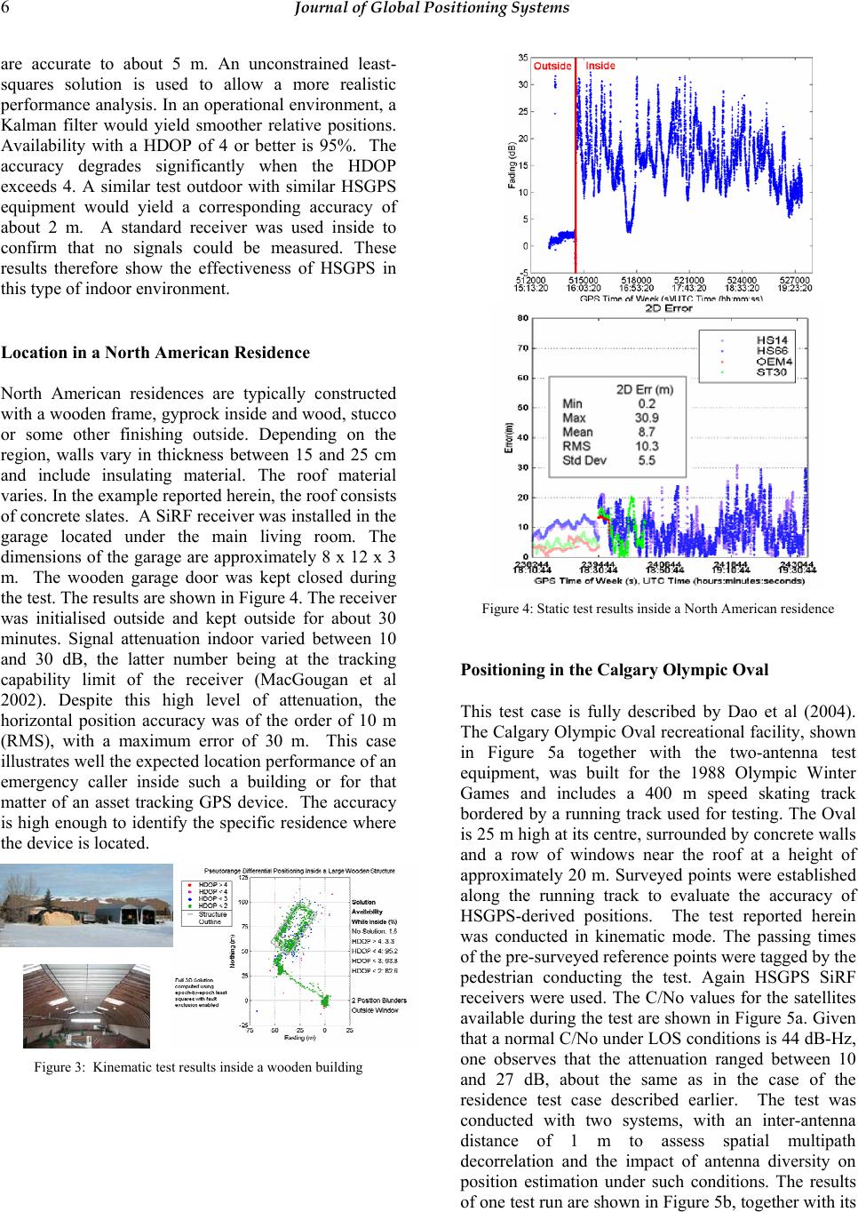 6 Journal of Global Positioning Systems are accurate to about 5 m. An unconstrained least- squares solution is used to allow a more realistic performance analysis. In an operational environment, a Kalman filter would yield smoother relative positions. Availability with a HDOP of 4 or better is 95%. The accuracy degrades significantly when the HDOP exceeds 4. A similar test outdoor with similar HSGPS equipment would yield a corresponding accuracy of about 2 m. A standard receiver was used inside to confirm that no signals could be measured. These results therefore show the effectiveness of HSGPS in this type of indoor environment. Location in a N o rth American Residence North American residences are typically constructed with a wooden frame, gyprock inside and wood, stucco or some other finishing outside. Depending on the region, walls vary in thickness between 15 and 25 cm and include insulating material. The roof material varies. In the example reported herein, the roof consists of concrete slates. A SiRF receiver was installed in the garage located under the main living room. The dimensions of the garage are approximately 8 x 12 x 3 m. The wooden garage door was kept closed during the test. The results are shown in Figure 4. The receiver was initialised outside and kept outside for about 30 minutes. Signal attenuation indoor varied between 10 and 30 dB, the latter number being at the tracking capability limit of the receiver (MacGougan et al 2002). Despite this high level of attenuation, the horizontal position accuracy was of the order of 10 m (RMS), with a maximum error of 30 m. This case illustrates well the expected location performance of an emergency caller inside such a building or for that matter of an asset tracking GPS device. The accuracy is high enough to identify the specific residence where the device is located. Figure 3: Kinematic test results inside a wooden building Figure 4: Static test results inside a North American residence Positioning in the Calgary Olympic Oval This test case is fully described by Dao et al (2004). The Calgary Olympic Oval recreational facility, shown in Figure 5a together with the two-antenna test equipment, was built for the 1988 Olympic Winter Games and includes a 400 m speed skating track bordered by a running track used for testing. The Oval is 25 m high at its centre, surrounded by concrete walls and a row of windows near the roof at a height of approximately 20 m. Surveyed points were established along the running track to evaluate the accuracy of HSGPS-derived positions. The test reported herein was conducted in kinematic mode. The passing times of the pre-surveyed reference points were tagged by the pedestrian conducting the test. Again HSGPS SiRF receivers were used. The C/No values for the satellites available during the test are shown in Figure 5a. Given that a normal C/No under LOS conditions is 44 dB-Hz, one observes that the attenuation ranged between 10 and 27 dB, about the same as in the case of the residence test case described earlier. The test was conducted with two systems, with an inter-antenna distance of 1 m to assess spatial multipath decorrelation and the impact of antenna diversity on position estimation under such conditions. The results of one test run are shown in Figure 5b, together with its 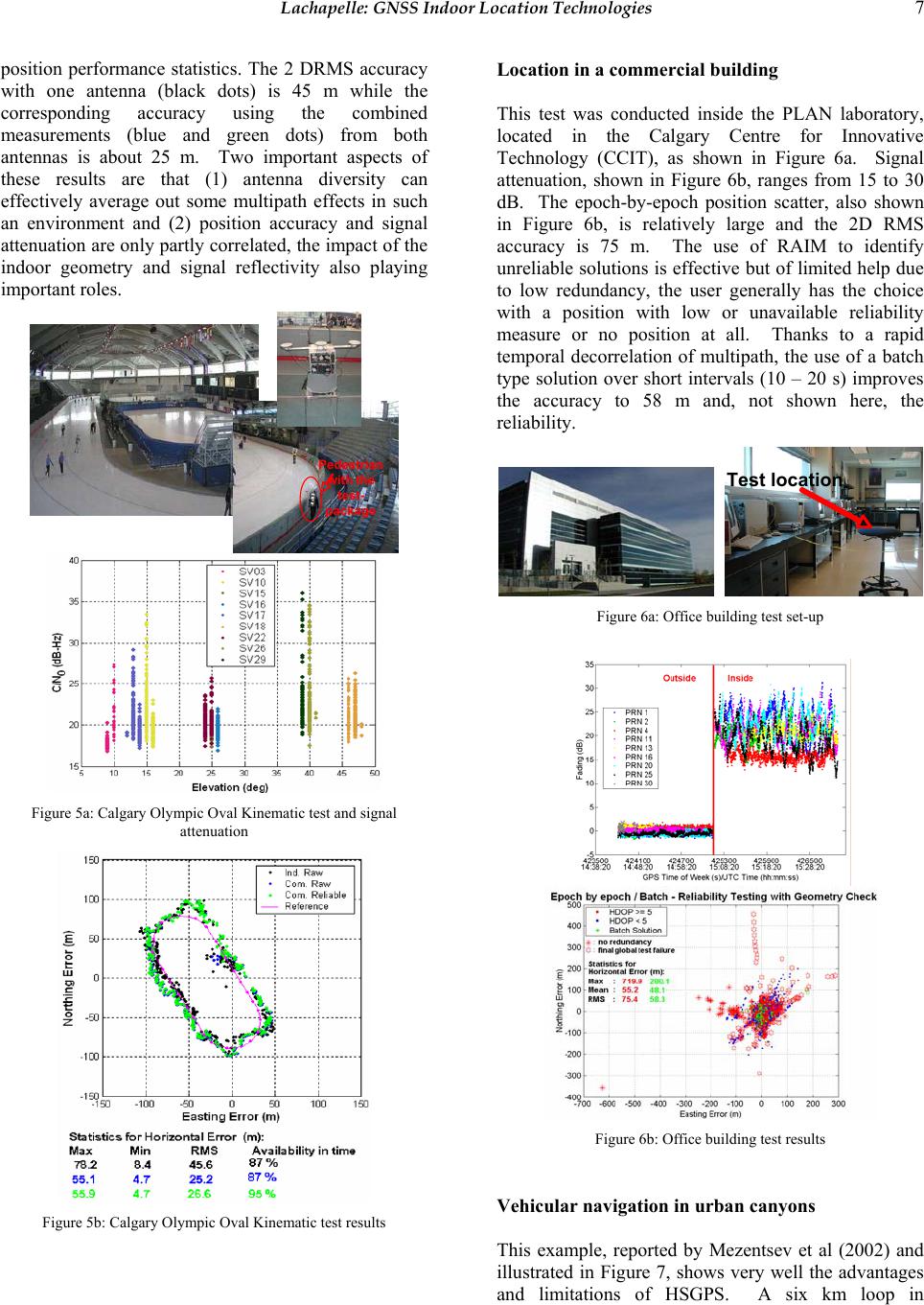 Lachapelle: GNSS Indoor Location Technologies 7 position performance statistics. The 2 DRMS accuracy with one antenna (black dots) is 45 m while the corresponding accuracy using the combined measurements (blue and green dots) from both antennas is about 25 m. Two important aspects of these results are that (1) antenna diversity can effectively average out some multipath effects in such an environment and (2) position accuracy and signal attenuation are only partly correlated, the impact of the indoor geometry and signal reflectivity also playing important roles. Pedestrian with the test- package Figure 5a: Calgary Olympic Oval Kinematic test and signal attenuation Figure 5b: Calgary Olympic Oval Kinematic test results Location in a commercial building This test was conducted inside the PLAN laboratory, located in the Calgary Centre for Innovative Technology (CCIT), as shown in Figure 6a. Signal attenuation, shown in Figure 6b, ranges from 15 to 30 dB. The epoch-by-epoch position scatter, also shown in Figure 6b, is relatively large and the 2D RMS accuracy is 75 m. The use of RAIM to identify unreliable solutions is effective but of limited help due to low redundancy, the user generally has the choice with a position with low or unavailable reliability measure or no position at all. Thanks to a rapid temporal decorrelation of multipath, the use of a batch type solution over short intervals (10 – 20 s) improves the accuracy to 58 m and, not shown here, the reliability. Test location Figure 6a: Office building test set-up Figure 6b: Office building test results Vehicular navigation in urban canyons This example, reported by Mezentsev et al (2002) and illustrated in Figure 7, shows very well the advantages and limitations of HSGPS. A six km loop in  8 Journal of Global Positioning Systems downtown Calgary was driven numerous times. That reported here is representative of the average performance. A standard receiver was used in addition to a SiRF receiver to show the performance differences. The UL (upper left) graph shows the trajectory in green and the fixes obtained with the standard receiver in blue. Availability is very low but accuracy very high. The UR graph shows the epoch- by-epoch least-squares fixes obtained with the HSGPS units. Availability is high but accuracy is low. No RAIM algorithm was applied and errors of hundreds of metres occur, due to echo-only signals reflected from buildings and, possibly, cross-correlation effects. The LL graph shows the HSGPS heavily filtered solution, which is generally quite good but benefits from the straight segments of the trajectory. The LR graph shows a solution (green) based on the integration of the HSGPS unit raw measurements with an automotive grade Murata rate gyro. In the latter case, availability is 100% and the accuracy is excellent, apart from a bias growing to 50 m in the LR section of the trajectory. Further augmentation by other vehicle’s components such as the ABS would likely further improve accuracy and would certainly improve reliability, although the latter was not systematically analyzed in this example. Figure 7: Vehicular navigation in urban canyons Pedestrian navigation in urban canyons This case is much more difficult than the vehicular case due to the more unpredictable nature of a pedestrian’s trajectory. A totally unpredictable turning radius might be a good way to describe this case! In the example shown in Figure 8 and conducted by Mezentsev et al (2004), a full six degrees of freedom MEMS IMU attached to the user’s waist is integrated with a HSGPS receiver in pedestrian dead reckoning (PDR) mode. The HSGPS receiver is a SiRF X-trac unit. The prototype test PDR unit consists of three gyros and three accelerometers built in a classical perpendicular triad scheme that represents a full six degrees of freedom low-cost IMU, as shown in Figure 8. The gyros used are Analog Devices ADXRS150 ±150°/s single chip rate gyros that are well suited for pedestrian navigation due to their small size (7 × 7 × 3 mm) and low power consumption (< 50 mW). The MEMS accelerometers used are VTI SCA 610 series. The total volume including a power regulation circuit is less than 100 cm3. In a commercial product, the volume of such unit would likely be of the order of a few cm3.  Lachapelle: GNSS Indoor Location Technologies 9 Since the IMU is attached to the body in a “semi-rigid” manner, its measured dynamics do indeed represent those of the user, which is not the case if the IMU was mounted in a PDA or mobile phone. The gyro triad is used to keep track of attitude. It is a complete tri-axis quaternion based attitude solution, so user's heading, pitch and roll are known. The accelerometers are used to detect steps. Also, optionally, they can be used to perform horizontal alignment at complete user stops. The user step length is initially assumed to be constant, say 70 cm. During use, it is calibrated when good GPS position solutions are available. In PDR mechanization, the position error is proportional to the distance traveled and not time as is the case in a classical INS mechanization. Given the position error growth characteristics of both approaches, the former (PDR) for a pedestrian significantly outperforms the latter, even with tactical grade systems over long periods of time (more than 1 minute of INS only navigation). The GPS-IMU PDR integration steps used are shown in Figure 8, together with the results of a 1.5 km loop in downtown Calgary. A RAIM algorithm was implemented to detect unreliable solutions. The unaided least-squares GPS position fixes are shown in green (reliable), red (Global test failure), and black (not enough redundancy to judge). The integrated HSGPS- IMU trajectory, obtained with a Kalman filter, is shown in blue. Its availability is nearly 100% while its maximum error reaches 50 m. An important question is what the performance gain would be if an ultra-tight integration was used. SiRF HSGPS Unit Low-Cost IMU- belt mounted Integration steps Detect a step Find heading Estimate step length PDR mechanization LSQ + RAIM HSGPS: Pos/Vel correlation INTEGRATION Kalman Filter Figure 8: Pedestrian navigation in urban canyons 4 Testing Procedures and Standards The test results shown in the previous section illustrate the difficulties associated with defining a sufficiently wide range of “standard” environments to fully test a commercial product purporting to meet pre-defined minimum operational performance standards (MOPS). Even if such environments were found, reproducibility would be an issue due to the spatial decorrelation of multipath, as was seen in the Calgary Olympic Oval for instance. In addition such environments would hardly be portable. In order to establish common testing standards, the question arises as to whether it is possible to construct realistic environments on a simulator. If this were possible it would resolve the above issues. An initial attempt was made by Spirent with the development of a new generation of simulators. Using its SimGEN software, it is possible to simulate a wide range of multipath scenarios, with different degrees of obstructions up to echo-only signals, while varying signal strength, as shown in Figure 9. The next step is to “stochastically” reproduce a realistic environment. This means simulating an environment with the same stochastic signal fading, multipath and temporal variation properties as those observed in an actual environment. Early attempts have resulted in encouraging results (Lachapelle et al 2003) but there is still much work to accomplish to obtain satisfactory results. Simulated Obstruction Zone - Cat A LOS-only zone - Cat B LOS+echoes zone - Cat C Echoes- only zone - Cat D Spirent Simulator Capability Figure 9: Indoor signal simulation scenario 5 Future Signals GPS II and Galileo signals will have significant advantages over the current GPS C/A code modulated L1 signal. The availability of pilot channels will allow the use of a pure PLL (Phase Lock Loop) and will result in more robust carrier phase tracking, avoiding the squaring loss currently present due to the need of a Costas loop. BOC (Binary Offset Carrier) modulation on the Galileo E5 and L1 (and GPS M-code) will improve mitigation of thermal noise, multipath and narrow band interference. Figure 10 shows the Cramer-Rao lower bounds for pseudorange accuracy for BOC(1,1)  10 Journal of Global Positioning Systems modulation (that will be used for Galileo L1) versus BPSK(1) (currently used on the GPS L1 signal). The Cramer-Rao lower bound shown only deals with thermal noise effects. The standard deviation difference between a BPSK(1) modulation using a 2- MHz pre-correlation bandwidth and a BOC (1,1) modulation using a 16-MHz bandwidth is nearly one order of magnitude. How this will translate in actual position accuracy in the presence of large multipath and echo-only signals remains to be determined. It should also be noted that BOC signal tracking could lead to biased pseudorange measurement due to its multi-peak auto-correlation function. This might particularly be a threat when low SNR are considered. Finally the use of secondary codes (on GPS L5 and Galileo L1, E5) will result in better narrow band interference mitigation and improved bit synchronization, although they might degrade the acquisition MTTF (Hegarty et al 2003; Macabiau et al 2003). Figure 10: Cramer-Rao lower bounds – BPSK(1) versus BOC(1,1) signal modulation techniques 6 Conclusion s The past 10 years have seen the birth, development and deployment of the first generation of indoor GPS technology. The current limitations of this technology are severe, as compared to the level of performance achievable to outdoor users. Yet, the technology is largely responsible for the emerging location-based services market, which has enormous potential for growth and impact. This market is becoming increasingly demanding in terms of performance. Accuracy is highly addictive! The question now is what will the technological improvements be during the next 10 years. One can safely predict significant to major improvements in the following areas: better signal tracking, use of new GPS and Galileo signals, and effective use of self-contained sensors and external aiding. Will these improvements be sufficient to keep up with users expectations? Acknowledgements The assistance of the following researchers in the PLAN Group, Department of Geomatics Engineering, the University of Calgary, are acknowledged: Drs. C. Ma and M. Petovello, senior research associates, and D. Dao, O. Julien, D. Karunanayake, H. Kuusniemi, O. Mezentsev, and B. Zheng, MSc and PhD candidates. References Chansarkar, M. and L. J. Garin (2000): Acquisition of GPS Signals at Very LowSignal to Noise Ratio. In Proceedings of the Institute of Navigation ION National Technical Meeting-2000 (January 26-28, 2000, Anaheim, California), pages 731–737. Dao, D., H. Kuusniemi, and G. Lachapelle (2004): HSGPS Reliability Enhancements Using aTwin-Antenna System. CD-ROM Proceedings of GNSS 2004 Conference, Rotterdam (16-19 May), 11 pages. Garin, L. J., M. Chansarkar, S. Miocinovic, C. Norman, and D. Hilgenberg (1999): Wireless Assisted GPS-SiRF Architecture and Field Test Results. In Proceedings of the Institute of Navigation ION GPS-99 (September 14- 17, 1999, Nashville, Tennessee), pages 489–497. Hegarty, C., M. Tran, and A.J. Van Dierendonck (2003): Acquisition Algorithms for GPS L5, CD-ROM Proceedings of the European Navigation Conference GNSS, (Graz, Austria, April 22-), 14 pages. Karunanayake, D., M.E. Cannon, G. Lachapelle, G. Cox (2004): Evaluation of AGPS in Weak Signal Environments Using a Hardware Simulator. Proceedings of GNSS 2004 (Session A6, Long Beach, CA, 21-24 September), The Institute of Navigation, Fairfax, VA Klukas, R., G. Lachapelle, and M. Fattouche (1998): Cellular Telephone Positioning Using GPS Time Synchronization. GPS World Magazine, 9, 4, 49-54. Klukas, R., G. Lachapelle, and M. Fattouche (1997): Field Tests of a Cellular Telephone Positioning System. Presented at IEEE VTC '97 - 47th Annual International Vehicular Technology Conference, Phoenix, AZ, May 5-7. Klukas, R., O. Julien, L. Dong, M.E. Cannon, and G. Lachapelle (2004): Effects of Building Materials on UHF Ranging Signals. GPS Solutions, 8, 1, 1-8. Kuusniemi, H., G. Lachapelle, and J. Takala (2004a): Reliability in Personal Positioning. CD-ROM Proceedings of GNSS 2004 Conference, Rotterdam (16- 19 May), 14 pages.  Lachapelle: GNSS Indoor Location Technologies 11 Kuusniemi, H., and G. Lachapelle (2004b): GNSS Signal Reliability Testing in Urban and Indoor Environments. Proceedings of NTM 2004 (San Diego, January 24-28), 210-224. Lachapelle, G., H. Kuusniemi, D. Dao, G. MacGougan, and M.E. Cannon (2004): HSGPS Signal Analysis and Performance Under Various Indoor Conditions. Navigation, U.S. Institute of Navigation, 51, 1, 29-43. Lachapelle, G., M.E. Cannon, R. Klukas, S. Singh, R. Watson, P. Boulton, A. Read and K. Jones (2003): Hardware Simulator Models and Methodologies for Controlled Performance Assessment of High Sensitivity AGPS Receivers. CD-ROM Proceedings of GNSS 2003, The European navigation Conference (Graz, Austria, 22-25 April), Session A2 on Indoor Navigation, 21 pages. Macabiau, C., L. Ries, F. Bastide, and J.-L. Issler (2003): GPS L5 Receiver Implementation Issues, Proceedings of the US Institute of Navigation GPS/GNSS (Portland, OR, USA, Sept. 9-12), pp. 153-164. MacGougan, G., G. Lachapelle, R. Klukas, K. Siu, L. Garin, J. Shewfelt, and G. Cox (2002) Performance Analysis of A Stand-Alone High Sensitivity Receiver. GPS Solutions, Springer Verlag, 6, 3, 179-195. Mezentsev, O., J. Collin, H. Kuusniemi, and G. Lachapelle (2004): Accuracy Assessment of a High Sensitivity GPS Based Pedestrian Navigation System Aided by Low-Cost Sensors. Proceedings of the 11th Saint Petersburg International Conference on Integrated Navigation Systems, 24-26 May, 156-164. Mezentsev , O., Y. Lu, G. Lachapelle, and R. Klukas (2002): Vehicular Navigation in Urban Canyons Using a High Sensitivity Receiver Augmented with a Low Cost Sensor. Proceedings of GPS2002 (Session E1, Portland, OR, 24-27 September), The Institute of Navigation, Alexandria, VA, 363-369. Moeglein, M. and N. Krasner (1998): An Introduction to SnapTrack Server-Aided GPS Technology. Proceedings of the Institute of Navigation ION GPS-98 (September 15-18, 1998, Nashville, Tennessee), pages 333–342. Peterson, B., D. Bruckner, and S. Heye (1997): Measuring GPS Signals Indoors. Proceedings of the Institute of Navigation ION GPS-97 (September 16-19, 1997, Kansas City, Missouri), pages 615–624. Syrjärinne, J. (2001): Studies of Modern Techniques for Personal Positioning, Publication 319. Phd, Tampere University of Technology. van Diggelen, F. and C. Abraham (2001): Indoor GPS, The No-Chip Challenge. GPS World, 12(9), pages 50–58. Weill, L, N. Kishimoto, S. Hirata, and K. Chin (2004): The next generation of a super sensitive GPS system. Proceedings of GNSS 2004 (Session A5, Long Beach, CA, 21-24 September), The Institute of Navigation, Fairfax, VA. |