 Wireless Sensor Network, 2010, 2, 599-605 doi:10.4236/wsn.2010.28071 Published Online August 2010 (http://www.SciRP.org/journal/wsn) Copyright © 2010 SciRes. WSN Joint Centralized Power Control and Cell Sectoring for Interference Management in CDMA Cellular Systems in a 2D Urban Environment Mohamad Dosaranian Moghadam1, Hamidreza Bakhshi2, Gholamreza Dadashzadeh2 1Department of Electrical Engineering, Qazvin Islamic Azad University, Qazvin, Iran 2Department of Electrical Engineering, Shahed University, Tehran, Iran E-mail: m_dmoghadam@qiau.ac.ir, {bakh shi, gdadashzadeh}@shahed.ac.ir Received May 15, 2010; revised May 26, 2010; accepted June 7, 2010 Abstract The interference reduction capability of cell sectoring and power control algorithms have been considered separately as means to decrease the interference in Code Division Multiple Access (CDMA) cellular systems. In this paper, we present Switched-Beam (SB) and Rotatable Equal Sectoring (RES) techniques for CDMA cellular systems in a 2D urban environment. In the SB technique by using a number of fixed, independent, or directional antennas we increase the downlink capacity of the CDMA systems. Also in the RES method, the equal sectors of the base stations are rotating together to decrease the inter-cell and intra-cell interferences. Also in this paper we use centralized power control to overcome the near-far problem. Simulation results indicate that the proposed techniques considerably increase the capacity of the CDMA cellular systems compared to ordinary Equal Sectoring (ES) method. Keywords: CDMA, Centralized Power Control, Equal Sectoring, Forward Link, Rotatable Equal Sectoring, Switched-Beam 1. Introduction Code-division multiple access (CDMA) for cellular communication networks requires the implementation of some forms of adaptive power control. In uplink of CDMA systems, the maximum number of supportable users per cell is limited by multipath fading, shadowing, and near-far effects that cause fluctuations of the re- ceived power at the base station (BS). Depending on the location where the decision on how to adjust the trans- mitted powers is made, the power control algorithms can be divided into two groups: centralized and distributed techniques [1-6]. In centralized power control, a network center can simultaneously compute the optimal power levels for all users. However, it requires measurement of all the link gains and the communication overhead be- tween a network center and base stations [7]. Distributed power control, on the other hand, uses only local infor- mation to determine transmitter power levels. It is much more scalable than centralized power control. However, transmitter power levels may not be optimal, resulting in performance degradation [8]. In this paper a centralized power control algorithm is used to compensate for near-far effects. Diversity and power control are two effective tech- niques for enhancing the signal to interference plus noise ratio (SINR) for wireless networks. Diversity exploits the random nature of radio propagation by finding inde- pendent (or, at least, highly uncorrelated) signal paths for communication. If one radio path undergoes a deep fade, another independent path may have a strong signal. By having more than one path to select from, the SINR at the receiver can be improved. The diversity scheme can be divided into three methods: 1) the space diversity; 2) the time diversity; 3) the frequency diversity [1]. In these schemes, the same information is first received (or transmitted) at different locations (or time slots/ fre- quency bands). After that, these signals are combined to increase the received SINR. The antenna array is an ex- ample of the space diversity, which uses a beamformer to increase the SINR for a particular direction [9,10]. In this paper we present switched-beam (SB) technique with antenna arrays in CDMA cellular systems. Also, we propose a method called rotatable equal sectoring (RES) This work was funded by the Islamic Azad University of Qazvin, Iran. 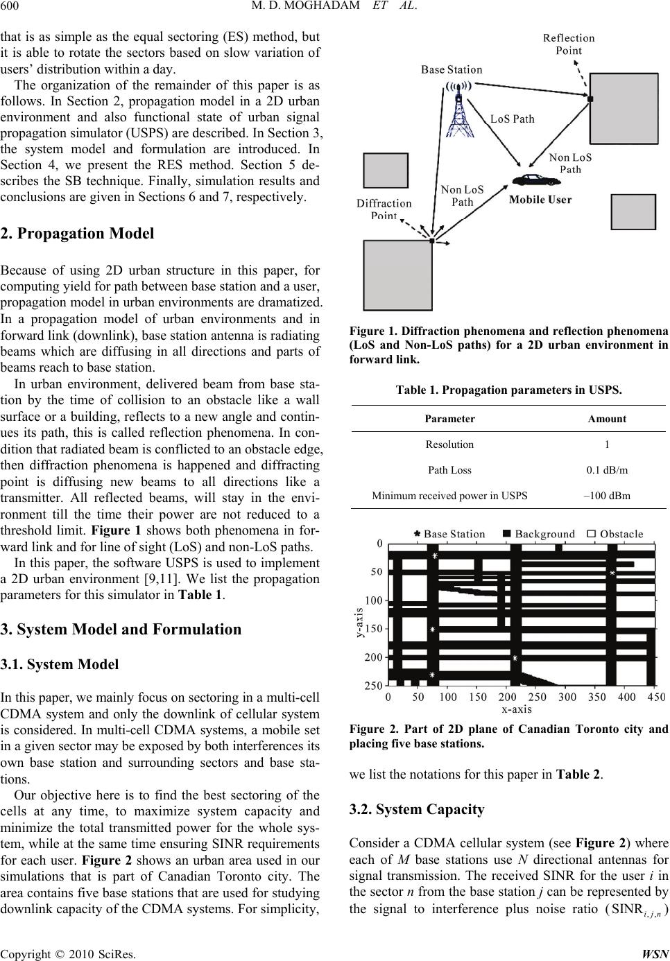 M. D. MOGHADAM ET AL. 600 that is as simple as the equal sectoring (ES) method, but it is able to rotate the sectors based on slow variation of users’ distribution within a day. The organization of the remainder of this paper is as follows. In Section 2, propagation model in a 2D urban environment and also functional state of urban signal propagation simulator (USPS) are described. In Section 3, the system model and formulation are introduced. In Section 4, we present the RES method. Section 5 de- scribes the SB technique. Finally, simulation results and conclusions are given in Sections 6 and 7, respectively. 2. Propagation Model Because of using 2D urban structure in this paper, for computing yield for path between base station and a user, propagation model in urban environments are dramatized. In a propagation model of urban environments and in forward link (downlink), base station antenna is radiating beams which are diffusing in all directions and parts of beams reach to base station. In urban environment, delivered beam from base sta- tion by the time of collision to an obstacle like a wall surface or a building, reflects to a new angle and contin- ues its path, this is called reflection phenomena. In con- dition that radiated beam is conflicted to an obstacle edge, then diffraction phenomena is happened and diffracting point is diffusing new beams to all directions like a transmitter. All reflected beams, will stay in the envi- ronment till the time their power are not reduced to a threshold limit. Figure 1 shows both phenomena in for- ward link and for line of sight (LoS) and non-LoS paths. In this paper, the software USPS is used to implement a 2D urban environment [9,11]. We list the propagation parameters for this simulator in Table 1. 3. System Model and Formulation 3.1. System Model In this paper, we mainly focus on sectoring in a multi-cell CDMA system and only the downlink of cellular system is considered. In multi-cell CDMA systems, a mobile set in a given sector may be exposed by both interferences its own base station and surrounding sectors and base sta- tions. Our objective here is to find the best sectoring of the cells at any time, to maximize system capacity and minimize the total transmitted power for the whole sys- tem, while at the same time ensuring SINR requirements for each user. Figure 2 shows an urban area used in our simulations that is part of Canadian Toronto city. The area contains five base stations that are used for studying downlink capacity of the CDMA systems. For simplicity, Figure 1. Diffraction phenomena and reflection phenomena (LoS and Non-LoS paths) for a 2D urban environment in forward link. Table 1. Propagation parameters in USPS. Parameter Amount Resolution 1 Path Loss 0.1 dB/m Minimum received power in USPS –100 dBm Figure 2. Part of 2D plane of Canadian Toronto city and placing five base stations. we list the notations for this paper in Table 2. 3.2. System Capacity Consider a CDMA cellular system (see Figure 2) where each of M base stations use N directional antennas for signal transmission. The received SINR for the user i in the sector n from the base station j can be represented by the signal to interference plus noise ratio () ,, SINRijn Copyright © 2010 SciRes. WSN 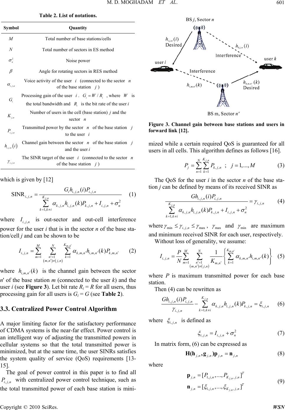 M. D. MOGHADAM ET AL.601 Table 2. List of notations. Symbol Quantity Total number of base stations/cells N Total number of sectors in ES method 2 n Noise power Angle for rotating sectors in RES method ,,ijn Voice activity of the user (connected to the sector of the base station in ) i G Processing gain of the user . i , where W is the total bandwidth and i i / i GWR is the bit rate of the user i ,jn Number of users in the cell (base station) and the sector n ,,ijn P Transmitted power by the sector of the base station n to the user i ,,ijn hi Channel gain between the sector of the base station n and the useri ,,ijn The SINR target of the user (connected to the sector of the base station i n ) which is given by [12] , ,, ,, ,, 2 ,, ,,,,,, 1, () SINR () jn iijn ijn ijn K kjn ijnkjnijnn kki Ghi P hkP I (1) where ,,ijn is out-sector and out-cell interference power for the user i that is in the sector n of the base sta- tion/cell j and can be shown to be , ,,,, ,,,, 11 1 ,, () mn K MN ijnkmn imnkmn mn k mn jn Ih kP (2) where is the channel gain between the sector n' of the base station m (connected to the user k) and the user i (see Figure 3). Let bit rate Ri = R for all users, thus processing gain for all users is Gi = G (see Table 2). ,, () imn hk 3.3. Centralized Power Control Algorithm A major limiting factor for the satisfactory performance of CDMA systems is the near-far effect. Power control is an intelligent way of adjusting the transmitted powers in cellular systems so that the total transmitted power is minimized, but at the same time, the user SINRs satisfies the system quality of service (QoS) requirements [13- 15]. The goal of power control in this paper is to find all with centralized power control technique, such as the total transmitted power of each base station is mini- ,,ijn P Figure 3. Channel gain between base stations and users in forward link [12]. mized while a certain required QoS is guaranteed for all users in all cells. This algorithm defines as follows [16]. , ,, 11 ;1,..., jn K N jkjn nk PPj M (3) The QoS for the user i in the sector n of the base sta- tion j can be defined by means of its received SINR as , ,, ,, ,, 2 ,, ,,,,,, 1, () () jn ijn ijn ijn K kjn ijnkjnijnn kki Ghi P hkP I (4) where min, ,maxijn , max and min are maximum and minimum received SINR for each user, respectively. Without loss of generality, we assume: , ,,, ,, , 11 1 , ,, 1() mn K MN ijnkmn imn mn k mn mn jn P hk NK where P is maximum transmitted power for each base station. Then (4) can be rewritten as , ,, ,, ,, ,,,,,, 1, ,, () () jn K ijn ijn kjni jnkjni jn kki ijn Ghi PhkP where ,,ijn is defined as 2 ,, ,,ijn ijnn I (7) In matrix form, (6) can be expressed as ,,, , njnjn jn H(h , )pn (8) where , , ,1,, ,, ,1,, ,, [,..., ] [,..., ] jn jn T jnjnK jn T jnjnK jn PP p n (9) Copyright © 2010 SciRes. WSN  M. D. MOGHADAM ET AL. 602 are the vectors of the transmitted powers and out-sector and out-cell interference plus noise power, respectively. Also in (8), ,1 jn K , n h ()l is the vector containing all channel gains for ,,ijn h, ,1,..., n il k,,jn g , and ,, , ., ] jn T K jn 1, , [ ,.. jn ,, ,, ,,, ,, ,, () for [] () for ijn ijn jnjn il ljn ijn Gh iil hl il H(h ,g) , Using (8), the optimal transmitted powers can be computed as [16] 1 ,,, [] njnjn pH(h, jn )n (11) 4. Rotatable Equal Sectoring Method A way of reducing the interference between users is to sectoring the cells using directional antennas. While this approach still utilizes the spatial domain to introduce or- thogonalization to the system, it is fundamentally differ- ent than beamforming. Beamforming method combines the received signals from multiple antennas in a unique way for each user to suppress the interference that the user sees. Sectoring merely employs directional antennas and each users signal is received at only one of these an- tennas. Since only a subset of the users is received at each antenna, the interference that each user sees is less com- pared to a single antenna system. No spatial combiner is used. While this is a more rigid scheme than beamform- ing, the simplicity of the resulting receivers is appealing and sectoring can be quite beneficial especially for static systems, if the users do not have to handoff from sector to sector very frequently [14,15]. It has been shown that sectoring increases the number of users admissible in a system. However under highly non-uniform traffic loads, conventional sectoring, i.e., ES method, which divides the cell into equal width sectors might fail to bring much capacity improvement. To increase the capacity of CDMA cellular systems, in this paper, the RES is proposed to reduce rejecting of call requests in situations like as traffic jams and crowded hours in entertainment places. This method is capable of rotating the pattern β de- grees in each direction, discretely. Hence, there are 360/(βN) possible different states, where N is the number of sectors for each base station. In the RES method, an- gle rotation of each base station is chosen such that the SINR of each user remains between γmin and γmax under minimizing the transmitted power of each base station. 5. Switched-Beam Technique One simple alternative to the fully adaptive antenna is the switched-beam architecture in which the best beam is chosen from a number of fixed steered beams. Switched- beam systems are technologically the simplest and can be implemented by using antenna arrays and or a number of fixed, independent, or directional antennas [17]. We list the SB technique conditions for this paper as follows. 1) According to Figure 4, beams coverage angle is 30˚ and overlap between consecutive beams is 20˚. Thus each base station has 36 beams. 2) Each user can use nmax beams for its each path to communicate with a base station at any time. In the SB technique, number of beams is chosen such that SINR of each user remains between γmin and γmax under minimiz- ing the transmitted power of each base station. In Figure 5, we show select of beams for three users with the SB technique for nmax = 2. It should be mentioned that using nmax = 2 means maximum two beams are paying service to users in form of unit beam. 6. Simulation Results In this section we present the simulation results to com- pare the performance of the RES, SB, and ES methods. The simulated ES method uses the distribution of users which can be seen in Figure 6 for pattern configuration of M = 5 base stations (see Figure 2). Since the ES method does not change this configuration according to the changes of the distribution, in some conditions this method is not able to handle many of call requests. But in case of using the RES method, we can improve the performance, as this method rotates the patterns of base stations according to the distribution of the users at each moment. In our simulation, we use the following parameter set- ting: Total number of base stations M = 5; total number of sectors in the ES method N = 3 (sector angle is 120˚); processing gain G = 512; voice activity for all users 1 ; noise power 22 n ; angles for rotating sectors in the RES method β = 10˚ and β = 30˚; maximum transmitted power for each base station P = 120W; γmax = 9 dB and γmin = 7 dB. In Figure 7, the number of active users in different hours of day and night in a day off for the RES, SB, and ES methods is compared. In such a day, we assume users are spending their spare time in places such as park, cinema and sport clubs and are gathered in two different places and around different hours (around 17 and 22 hours). As you can see especially around mentioned time in region we face crises, increasing capacity for the RES method is very considerable in comparison with the ES method. This increasing capacity for the RES method and for β = 10˚ is higher than β = 30˚, because the system has more degrees of freedom. In addition, we see that the number of active users in mentioned time with the SB Copyright © 2010 SciRes. WSN  M. D. MOGHADAM ET AL.603 Figure 4. 36 beams in each base station with switched-beam technique. Figure 5. Select of beam for three users with switched-beam technique. Figure 6. Distribution of users in the ES method. technique is higher than the RES and ES methods, be- cause in the SB technique the interference is lower than the RES and ES methods. It should be mentioned that increasing the number of active users in the SB technique, will lead more complexity in receiver in comparison with the RES and ES methods. Also it can be seen that the number of active users with the SB technique for nmax = 3 is higher than the other cases (nmax = 1, nmax = 2). Figure 8 shows the comparison of the number of ac- tive users in different hours of a day and night in a working day for the RES, SB, and ES methods. This study is assumed where highest user demands for con- centration on conversation are happened around 7.30, 12.30 and 16.30 (starting and finishing times for educa- tional centres, offices, and …). Similar to Figure 7, we observe that the number of active users in the RES method is much higher than the ES method and also is lower than the SB technique. Also it can be seen that the number of users in the RES method and for β = 10˚ is higher than β = 30˚. Figure 7. Number of active users (Normalized) for the RES, SB, and ES methods in a day off. Figure 8. Number of active users (Normalized) for the RES, SB, and ES methods on a working day. Figure 9. The average of active users (Normalized) for the RES, SB, and ES methods in a day off. Copyright © 2010 SciRes. WSN 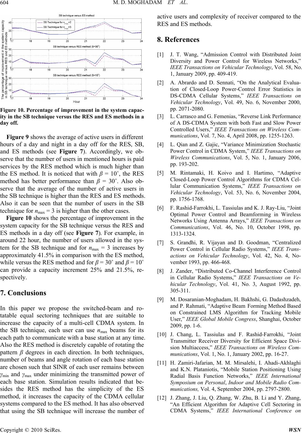 M. D. MOGHADAM ET AL. 604 Figure 10. Percentage of improvement in the system capac- ity in the SB technique versus the RES and ES methods in a day off. Figure 9 shows the average of active users in different hours of a day and night in a day off for the RES, SB, and ES methods (see Figure 7). Accordingly, we ob- serve that the number of users in mentioned hours is paid services by the RES method which is much higher than the ES method. It is noticed that with β = 10˚, the RES method has better performance than β = 30˚. Also ob- serve that the average of the number of active users in the SB technique is higher than the RES and ES methods. Also it can be seen that the number of users in the SB technique for nmax = 3 is higher than the other cases. Figure 10 shows the percentage of improvement in the system capacity for the SB technique versus the RES and ES methods in a day off (see Figure 7). For example, in around 22 hour, the number of users allowed in the sys- tem for the SB technique and for nmax = 3 increases by approximately 41.5% in comparison with the ES method, while versus the RES method and for β = 30˚ and β = 10˚ can provide a capacity increment 25% and 21.5%, re- spectively. 7. Conclusions In this paper we propose the switched-beam and ro- tatable equal sectoring techniques that are suitable to increase the capacity of a multi-cell CDMA system. In the SB technique, each user can use nmax beams for its each path to communicate with a base station at any time. Also the RES method is discretely capable of rotating the pattern β degrees in each direction. In both techniques, number of beams and angle rotation of each base station are chosen such that SINR of each user remains between γmin and γmax under minimizing the transmitted power of each base station. Simulation results indicated that be- sides the RES method has the simplicity of the ES method, it increases the capacity of the CDMA cellular systems compared to the ES method. It has also observed that using the SB technique will increase the number of active users and complexity of receiver compared to the RES and ES methods. 8. References [1] J. T. Wang, “Admission Control with Distributed Joint Diversity and Power Control for Wireless Networks,” IEEE Transactions on Vehicular Technology, Vol. 58, No. 1, January 2009, pp. 409-419. [2] A. Abrardo and D. Sennati, “On the Analytical Evalua- tion of Closed-Loop Power-Control Error Statistics in DS-CDMA Cellular Systems,” IEEE Transactions on Vehicular Technology, Vol. 49, No. 6, November 2000, pp. 2071-2080. [3] L. Carrasco and G. Femenias, “Reverse Link Performance of A DS-CDMA System with both Fast and Slow Power Controlled Users,” IEEE Transactions on Wireless Com- munications, Vol. 7, No. 4, April 2008, pp. 1255-1263. [4] L. Qian and Z. Gajic, “Variance Minimization Stochastic Power Control in CDMA System,” IEEE Transactions on Wireless Communications, Vol. 5, No. 1, January 2006, pp. 193-202. [5] M. Rintamaki, H. Koivo and I. Hartimo, “Adaptive Closed-Loop Power Control Algorithms for CDMA Cel- lular Communication Systems,” IEEE Transactions on Vehicular Technology, Vol. 53, No. 6, November 2004, pp. 1756-1768. [6] F. Rashid-Farrokhi, L. Tassiulas and K. J. Ray-Liu, “Joint Optimal Power Control and Beamforming in Wireless Networks Using Antenna Arrays,” IEEE Transactions on Communications, Vol. 46, No. 10, October 1998, pp. 1313-1324. [7] S. Grandhi, R. Vijayan and D. Goodman, “Centralized Power Control in Cellular Radio Systems,” IEEE Trans- actions on Vehicular Technology, Vol. 42, No. 4, No- vember 1993, pp. 466-468. [8] J. Zander, “Distributed Co-Channel Interference Control in Cellular Radio Systems,” IEEE Transactions on Ve- hicular Technology, Vol. 41, No. 3, August 1992, pp. 305-311. [9] M. Dosaranian-Moghadam, H. Bakhshi, G. Dadashzadeh, and P. Rahmati, “Adaptive Beam Forming Method Based on Constrained LMS Algorithm for Tracking Mobile User,” IEEE Global Mobile Congress, Shanghai, October 2009, pp. 1-6. [10] J. Chang, L. Tassiulas and F. Rashid-Farrokhi, “Joint Transmitter Receiver Diversity for Efficient Space Divi- sion Multiaccess,” IEEE Transactions on Wireless Com- munications, Vol. 1, No. 1, January 2002, pp. 16-27. [11] H. Zamiri-Jafarian, M. M. Mirsalehi, I. Ahadi-Akhlaghi and K.N. Plataniotis, “Mobile Station Positioning Using Radial Basis Function Networks,” IEEE International Symposium on Personal, Indoor and Mobile Radio Com- munications, Vol. 4, September 2004, pp. 2797-2800. [12] J. Zhang, J. Liu, Q. Zhang, W. Zhu, B. Li and Y. Zhang, “An Efficient Algorithm for Adaptive Cell Sectoring in CDMA Systems,” IEEE International Conference on Copyright © 2010 SciRes. WSN  M. D. MOGHADAM ET AL. Copyright © 2010 SciRes. WSN 605 Communications, Anchorage, Vol. 2, May 2003, pp. 1238-1242. [13] S. Kandukuri and S. Boyd, “Optimal Power Control in Interference-Limited Fading Wireless Channels with Outage Probability Specifications,” IEEE Transactions on Wireless Communication, Vol. 1, No. 1, January 2002, pp. 46-55. [14] M. Rintamaki, H. Koivo and I. Hartimo, “Adaptive Closed-Loop Power Control Algorithms for CDMA Cel- lular Communication Systems,” IEEE Transactions on Vehicular Technology, Vol. 53, No. 6, November 2004, pp. 1756-1768. [15] R. Zhang, C. C. Chai and Y. Liang, “Joint Beam Forming and Power Control for Multiantenna Relay Broadcast Channel with Qos Constraints,” IEEE Transactions on Signal Processing, Vol. 57, No. 2, February 2009, pp. 726-737. [16] A. F. Almutairi, S. L. Miller, H. A. Latchman and T. F. Wong, “Power Control Algorithm for MMSE Receiver Based CDMA Systems,” IEEE Communications Letters, Vol. 4, No. 11, November 2000, pp. 346-348. [17] B. Allen and M. Beach, “On the Analysis of Switched- Beam Antennas for the W-CDMA Downlink,” IEEE Transactions on Vehicular Technology, Vol. 53, No. 3, May 2004, pp. 569-578.
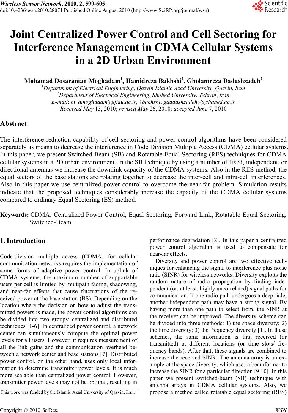
|