Paper Menu >>
Journal Menu >>
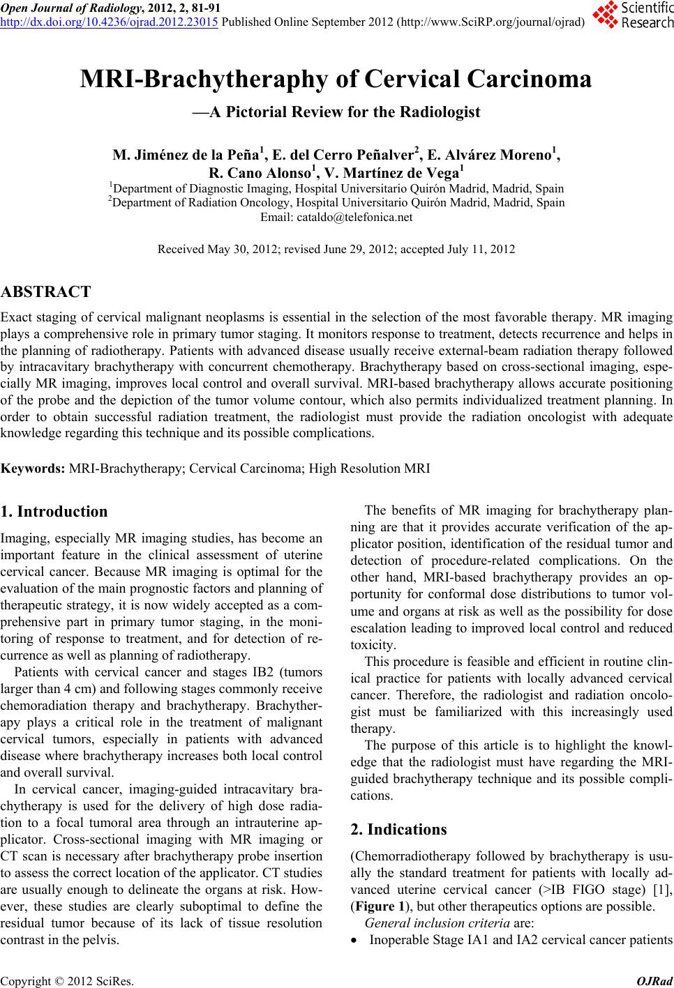 Open Journal of Radiology, 2012, 2, 81-91 http://dx.doi.org/10.4236/ojrad.2012.23015 Published Online September 2012 (http://www.SciRP.org/journal/ojrad) MRI-Brachytheraphy of Cervical Carcinoma —A Pictorial Review for the Radiologist M. Jiménez de la Peña1, E. del Cerro Peñalver2, E. Alvárez Moreno1, R. Cano Alonso1, V. Martínez de Vega1 1Department of Diagnostic Imaging, Hospital Universitario Quirón Madrid, Madrid, Spain 2Department of Radiation Oncology, Hospital Universitario Quirón Madrid, Madrid, Spain Email: cataldo@telefonica.net Received May 30, 2012; revised June 29, 2012; accepted July 11, 2012 ABSTRACT Exact staging of cervical malignant neoplasms is essential in the selection of the most favorable therapy. MR imaging plays a comprehensive role in primary tumor staging. It monitors response to treatment, detects recurrence and helps in the planning of radiotherapy. Patients with advanced disease usually receive external-beam radiation therapy followed by intracavitary brachytherapy with concurrent chemotherapy. Brachytherapy based on cross-sectional imaging, espe- cially MR imaging, improves local control and overall survival. MRI-based brachytherapy allows accurate positioning of the probe and the depiction of the tumor volume contour, which also permits individualized treatment planning. In order to obtain successful radiation treatment, the radiologist must provide the radiation oncologist with adequate knowledge regarding this technique and its possible complications. Keywords: MRI-Brachytherapy; Cervical Carcinoma; High Resolution MRI 1. Introduction Imaging, especially MR imaging studies, has become an important feature in the clinical assessment of uterine cervical cancer. Because MR imaging is optimal for the evaluation of the main progno stic factors and p lanning of therapeutic strategy, it is now widely accepted as a com- prehensive part in primary tumor staging, in the moni- toring of response to treatment, and for detection of re- currence as well as planning of radiotherapy. Patients with cervical cancer and stages IB2 (tumors larger than 4 cm) and following stages commonly receive chemoradiation therapy and brachytherapy. Brachyther- apy plays a critical role in the treatment of malignant cervical tumors, especially in patients with advanced disease where brachytherapy increases both local control and overall survival. In cervical cancer, imaging-guided intracavitary bra- chytherapy is used for the delivery of high dose radia- tion to a focal tumoral area through an intrauterine ap- plicator. Cross-sectional imaging with MR imaging or CT scan is necessary after brachytherapy probe insertion to assess the correct location of the app licator. CT studies are usually enough to delineate the organs at risk. How- ever, these studies are clearly suboptimal to define the residual tumor because of its lack of tissue resolution contrast in the pelvis. The benefits of MR imaging for brachytherapy plan- ning are that it provides accurate verification of the ap- plicator position, identification of the residual tumor and detection of procedure-related complications. On the other hand, MRI-based brachytherapy provides an op- portunity for conformal dose distributions to tumor vol- ume and organs at risk as well as the possibility for dose escalation leading to improved local control and reduced toxicity. This procedure is feasible and efficient in rou tine clin- ical practice for patients with locally advanced cervical cancer. Therefore, the radiologist and radiation oncolo- gist must be familiarized with this increasingly used therapy. The purpose of this article is to highlight the knowl- edge that the radiologist must have regarding the MRI- guided brachytherapy technique and its possible compli- cations. 2. Indications (Chemorradiotherapy followed by brachytherapy is usu- ally the standard treatment for patients with locally ad- vanced uterine cervical cancer (>IB FIGO stage) [1], (Figure 1), but other therapeutics options are possible. General inclusion criteria are: Inoperable Stage IA1 and IA2 cervical cancer patients C opyright © 2012 SciRes. OJRad 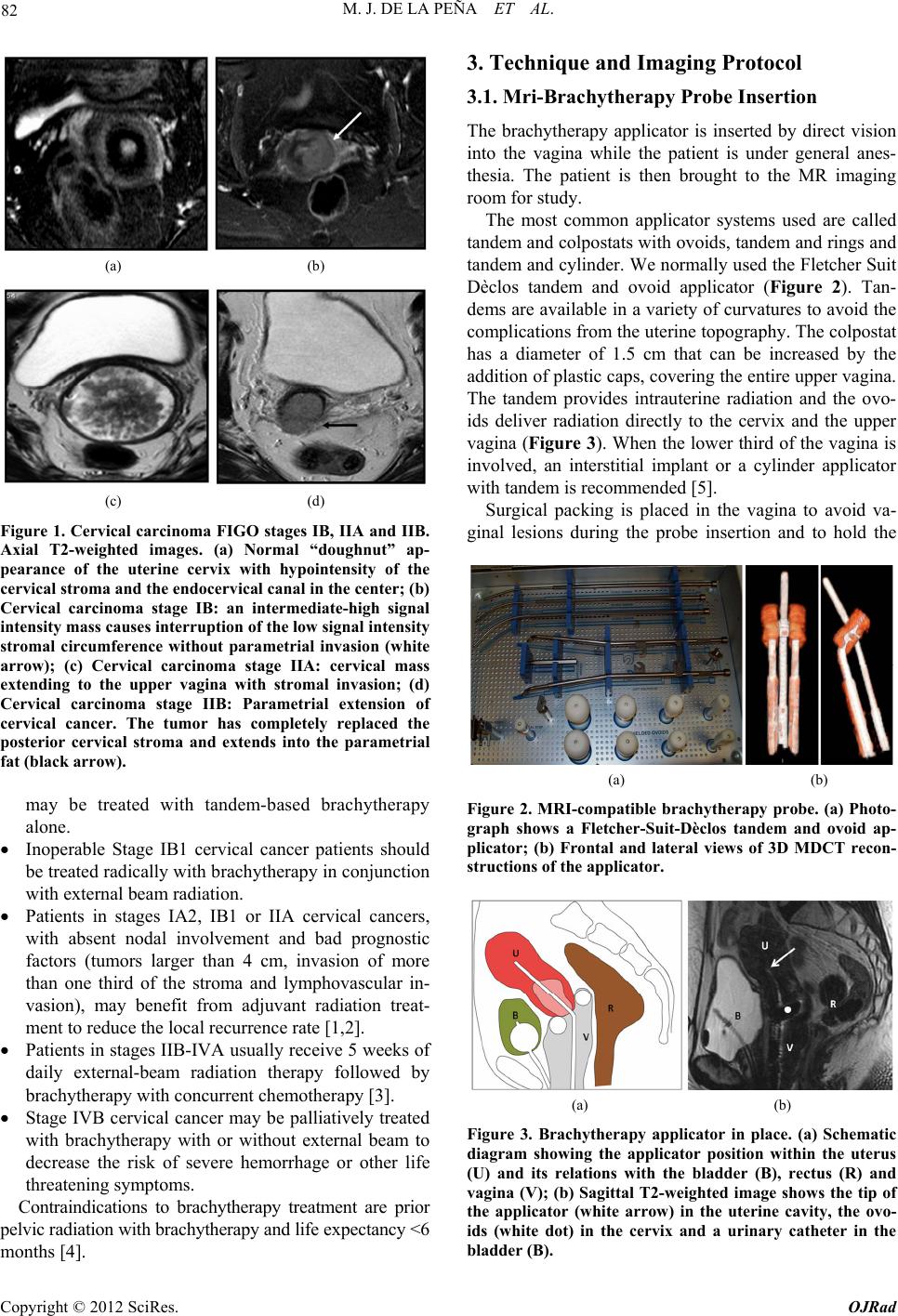 M. J. DE LA PEÑA ET AL. 82 (a) (b) (c) (d) Figure 1. Cervical carcinoma FIGO stages IB, IIA and IIB. Axial T2-weighted images. (a) Normal “doughnut” ap- pearance of the uterine cervix with hypointensity of the cervical stroma and the endocervical canal in the center; (b) Cervical carcinoma stage IB: an intermediate-high signal intensity mass causes interruption of the low signal intensity stromal circumference without parametrial invasion (white arrow); (c) Cervical carcinoma stage IIA: cervical mass extending to the upper vagina with stromal invasion; (d) Cervical carcinoma stage IIB: Parametrial extension of cervical cancer. The tumor has completely replaced the posterior cervical stroma and extends into the parametrial fat (black arrow). may be treated with tandem-based brachytherapy alone. Inoperable Stage IB1 cervical cancer patients should be treated radically with b rachyth erapy in conju nction with external beam radiation. Patients in stages IA2, IB1 or IIA cervical cancers, with absent nodal involvement and bad prognostic factors (tumors larger than 4 cm, invasion of more than one third of the stroma and lymphovascular in- vasion), may benefit from adjuvant radiation treat- ment to reduce the local recurrence rate [1,2]. Patients in stages IIB-IVA usually receive 5 weeks of daily external-beam radiation therapy followed by brachytherapy with concurrent chemotherapy [3]. Stage IVB cervical cancer may be palliatively treated with brachytherapy with or without external beam to decrease the risk of severe hemorrhage or other life threatening symptoms. Contraindications to brachytherapy treatment are prior pelvic radiation with brachytherapy and life expectancy <6 months [4]. 3. Technique and Imaging Protocol 3.1. Mri-Brachytherapy Probe Insertion The brachytherapy applicator is inserted by direct vision into the vagina while the patient is under general anes- thesia. The patient is then brought to the MR imaging room for study. The most common applicator systems used are called tandem and colpostats with ovoids, tandem and rings and tandem and cylinder. We normally used the Fletcher Suit Dèclos tandem and ovoid applicator (Figure 2). Tan- dems are available in a variety of curvatures to avoid the complications from the uterine topog raphy. The colpo stat has a diameter of 1.5 cm that can be increased by the addition of plastic caps, covering th e entire upper vagina. The tandem provides intrauterine radiation and the ovo- ids deliver radiation directly to the cervix and the upper vagina (Figure 3). When the lower third of the vagina is involved, an interstitial implant or a cylinder applicator with tandem is recommended [5]. Surgical packing is placed in the vagina to avoid va- ginal lesions during the probe insertion and to hold the (a) (b) Figure 2. MRI-compatible brachytherapy probe. (a) Photo- graph shows a Fletcher-Suit-Dèclos tandem and ovoid ap- plicator; (b) Frontal and lateral views of 3D MDCT recon- structions of the applicator. (a) (b) Figure 3. Brachytherapy applicator in place. (a) Schematic diagram showing the applicator position within the uterus (U) and its relations with the bladder (B), rectus (R) and vagina (V); (b) Sagittal T2-weighted image shows the tip of the applicator (white arrow) in the uterine cavity, the ovo- ids (white dot) in the cervix and a urinary catheter in the bladder (B). Copyright © 2012 SciRes. OJRad 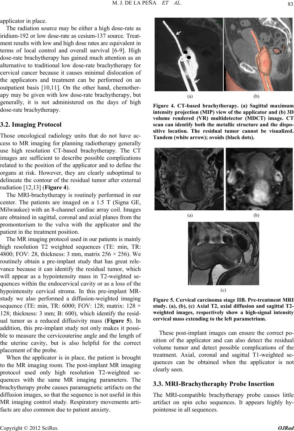 M. J. DE LA PEÑA ET AL. 83 applicator in place. The radiation source may be either a high dose-rate as iridium-192 or low dose-rate as cesium-137 source. Treat- ment results with low and high dose rates are equivalent in terms of local control and overall survival [6-9]. High dose-rate brachytherapy has gained much attention as an alternative to traditional low dose-rate brachytherapy for cervical cancer because it causes minimal dislocation of the applicators and treatment can be performed on an outpatient basis [10,11]. On the other hand, chemother- apy may be given with low dose-rate brachytherapy, but generally, it is not administered on the days of high dose-rate brachytherapy. 3.2. Imaging Protocol Those oncological radiology units that do not have ac- cess to MR imaging for planning radiotherapy generally use high resolution CT-based brachytherapy. The CT images are sufficient to describe possible complications related to the position of the applicator and to define the organs at risk. However, they are clearly suboptimal to delineate the contour of the residual tumor after external radiation [12,13] (Figure 4). The MRI-brachytherapy is routinely performed in our center. The patients are imaged on a 1.5 T (Signa GE, Milwaukee) with an 8-channel cardiac array coil. Images are obtained in sagittal, coronal and axial p lanes from the promontorium to the vulva with the applicator and the patient in the treatment position . The MR imaging protocol used in our patients is mainly high resolution T2 weighted sequences (TE: min, TR: 4800; FOV: 2 8, thickness: 3 mm, matrix 256 × 2 56). We routinely obtain a pre-implant study that has great rele- vance because it can identify the residual tumor, which will appear as a hypointensity mass in T2-weighted se- quences within the endocervical cavity or as a loss of the hypointensity cervical stroma. In this pre-implant MR- study we also performed a diffusion-weighted imaging sequence (TE: min, TR: 6000; FOV: 128; matrix: 128 × 128; thickness: 3 mm; B: 600), which identify the resid- ual tumor as a reduced diffusivity mass (Figure 5). In addition, this pre-implant study not only makes it possi- ble to measure the cervicouterine angle and the length of the uterine cavity, but is also helpful for the correct placement of the probe. When the applicator is in place, the patient is brought to the MR imaging room. The post-implant MR imaging protocol used only high resolution T2-weighted se- quences with the same MR imaging parameters. The brachytherapy probe causes paramagnetic artifacts on the diffusion images, so that the sequence is not useful in this MR imaging control study. Respiratory movements arti- facts are also common due to patient anxiety. (a) (b) Figure 4. CT-based brachytherapy. (a) Sagittal maximum intensity projection (MIP) view of the applicator and (b) 3D volume rendered (VR) multidetector (MDCT) image. CT scan can identify both the metallic structure and the dispo- sitive location. The residual tumor cannot be visualized. Tandem (white arrow); ovoids (black dots). (a) (b) (c) Figure 5. Cervical carcinoma stage IIB. Pre-treatment MRI study. (a), (b), (c) Axial T2, axial diffusion and sagittal T2- weighted images, respectively show a high-signal intensity cervical mass extending to the left parametrium. These post-implant images can ensure the correct po- sition of the applicator and can also detect the residual volume tumor and detect possible complications of the treatment. Axial, coronal and sagittal T1-weighted se- quences can be obtained when the applicator is not clearly seen. 3.3. MRI-Brachytheraphy Probe Insertion The MRI-compatible brachytherapy probe causes little artifact on spin echo sequences. It appears highly hy- pointense in all sequences. Copyright © 2012 SciRes. OJRad 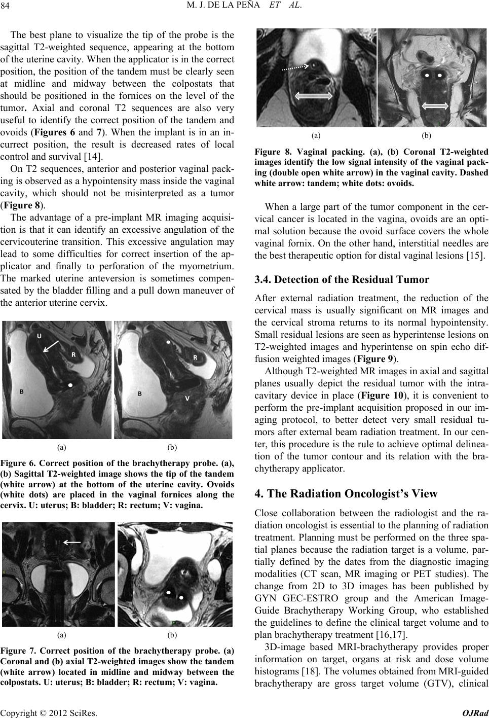 M. J. DE LA PEÑA ET AL. 84 The best plane to visualize the tip of the probe is the sagittal T2-weighted sequence, appearing at the bottom of the uterine cavity. When the applicator is in the correct position, the position of the tandem must be clearly seen at midline and midway between the colpostats that should be positioned in the fornices on the level of the tumor. Axial and coronal T2 sequences are also very useful to identify the correct position of the tandem and ovoids (Figures 6 and 7). When the implant is in an in- currect position, the result is decreased rates of local control and survival [14]. On T2 sequences, anterior and posterior vaginal pack- ing is observed as a hypointensity mass inside the vaginal cavity, which should not be misinterpreted as a tumor (Figure 8). The advantage of a pre-implant MR imaging acquisi- tion is that it can identify an excessive angulation of the cervicouterine transition. This excessive angulation may lead to some difficulties for correct insertion of the ap- plicator and finally to perforation of the myometrium. The marked uterine anteversion is sometimes compen- sated by the bladder filling an d a pull down maneuver of the anterior uterine cervix. (a) (b) Figure 6. Correct position of the brachytherapy probe. (a), (b) Sagittal T2-weighted image shows the tip of the tandem (white arrow) at the bottom of the uterine cavity. Ovoids (white dots) are placed in the vaginal fornices along the cervix. U: uterus; B: bladder; R: rectum; V: vagina. (a) (b) Figure 7. Correct position of the brachytherapy probe. (a) Coronal and (b) axial T2-weighted images show the tandem (white arrow) located in midline and midway between the colpostats. U: uterus; B: bladder; R: rectum; V: vagina. (a) (b) Figure 8. Vaginal packing. (a), (b) Coronal T2-weighted images identify the low signal intensity of the vaginal pack- ing (double open white arrow) in the vaginal cavity. Dashed white arrow: tandem; white dots: ovoids. When a large part of the tumor component in the cer- vical cancer is located in the vagina, ovoids are an opti- mal solution because the ovoid surface covers the whole vaginal fornix. On the other hand, interstitial needles are the best therapeutic option for distal vaginal lesions [15]. 3.4. Detection of the Residual Tumor After external radiation treatment, the reduction of the cervical mass is usually significant on MR images and the cervical stroma returns to its normal hypointensity. Small residual lesions are seen as hyperintense lesions on T2-weighted images and hyperintense on spin echo dif- fusion weighted images (Figure 9). Although T2-weighted MR images in axial and sagittal planes usually depict the residual tumor with the intra- cavitary device in place (Figure 10), it is convenient to perform the pre-implant acquisition proposed in our im- aging protocol, to better detect very small residual tu- mors after external beam radiation treatment. In our cen- ter, this procedure is the rule to achieve optimal delinea- tion of the tumor contour and its relation with the bra- chytherapy applicator. 4. The Radiation Oncologist’s View Close collaboration between the radiologist and the ra- diation oncologist is essential to th e planning of radiation treatment. Planning must be performed on the three spa- tial planes because the radiation target is a volume, par- tially defined by the dates from the diagnostic imaging modalities (CT scan, MR imaging or PET studies). The change from 2D to 3D images has been published by GYN GEC-ESTRO group and the American Image- Guide Brachytherapy Working Group, who established the guidelines to define the clinical target volume and to plan brachytherapy treatment [16,17]. 3D-image based MRI-brachytherapy provides proper information on target, organs at risk and dose volume histograms [18]. The volumes obtained from MRI-guided brachytherapy are gross target volume (GTV), clinical Copyright © 2012 SciRes. OJRad 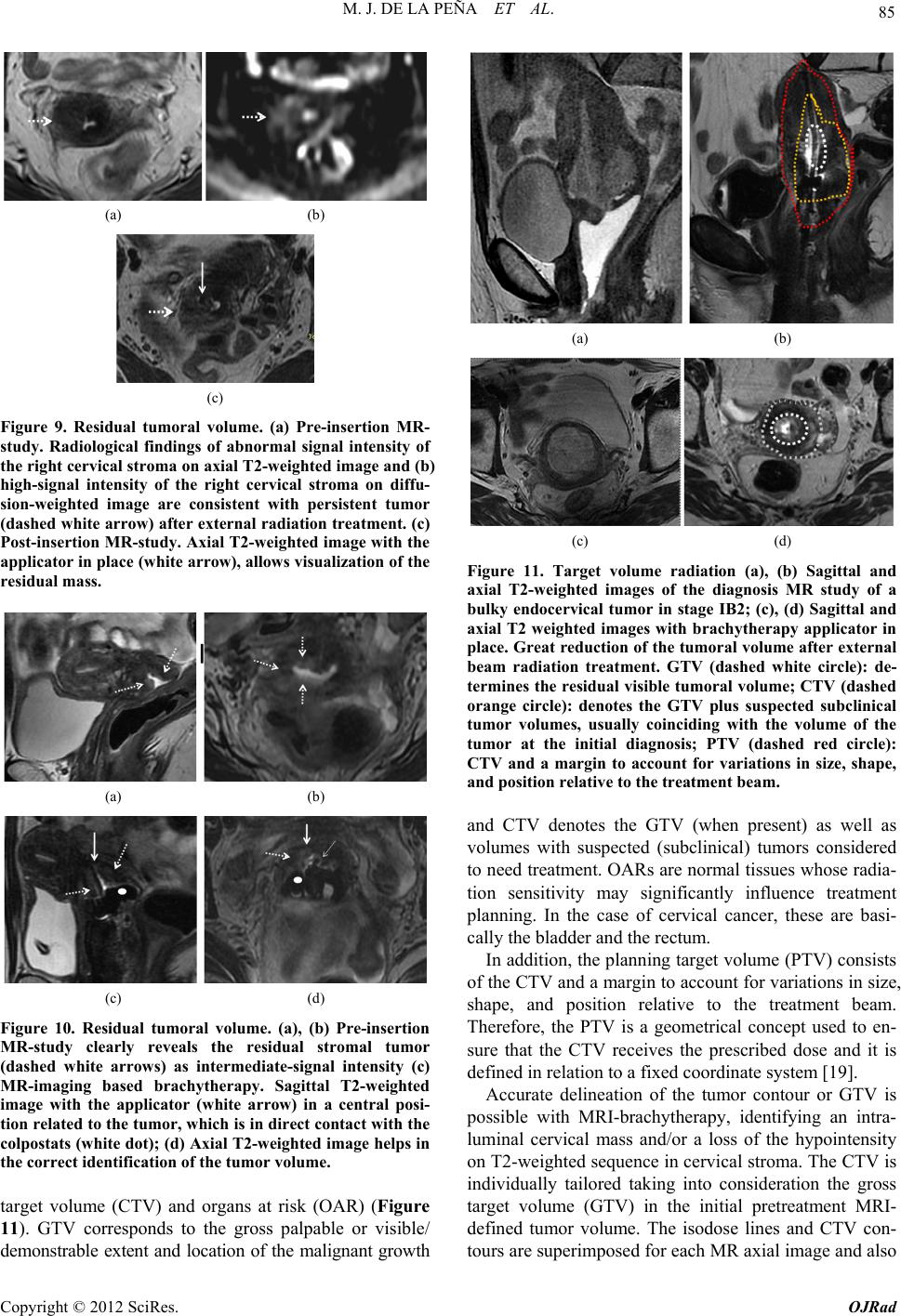 M. J. DE LA PEÑA ET AL. 85 (a) (b) (c) Figure 9. Residual tumoral volume. (a) Pre-insertion MR- study. Radiological findings of abnormal signal intensity of the right cervical stroma on axial T2-weighted image and (b) high-signal intensity of the right cervical stroma on diffu- sion-weighted image are consistent with persistent tumor (dashed white arrow) after external radiation treatment. (c) Post-insertion MR-study. Axial T2-weighted image with the applicator in place (white arrow), allows visualization of the residual mass. (a) (b) (c) (d) Figure 10. Residual tumoral volume. (a), (b) Pre-insertion MR-study clearly reveals the residual stromal tumor (dashed white arrows) as intermediate-signal intensity (c) MR-imaging based brachytherapy. Sagittal T2-weighted image with the applicator (white arrow) in a central posi- tion related to the tumor, which is in direct contact with the colpostats (white dot); (d) Axial T2-weighted image helps in the correct identification of the tumor volume. target volume (CTV) and organs at risk (OAR) (Figure 11). GTV corresponds to the gross palpable or visible/ demonstrable extent and location of the malignant growth (a) (b) (c) (d) Figure 11. Target volume radiation (a), (b) Sagittal and axial T2-weighted images of the diagnosis MR study of a bulky endocervical tumor in stage IB2; (c), (d) Sagittal and axial T2 weighted images with brachytherapy applicator in place. Great reduction of the tumoral volume after external beam radiation treatment. GTV (dashed white circle): de- termines the residual visible tumoral volume; CTV (dashed orange circle): denotes the GTV plus suspected subclinical tumor volumes, usually coinciding with the volume of the tumor at the initial diagnosis; PTV (dashed red circle): CTV and a margin to account for variations in size, shape, and position relative to the treatment beam. and CTV denotes the GTV (when present) as well as volumes with suspected (subclinical) tumors considered to need treatment. OARs are normal tissues whose radia- tion sensitivity may significantly influence treatment planning. In the case of cervical cancer, these are basi- cally the bladder and the rectum. In addition, the planning target volume (PTV) consists of the CTV and a margin to account for variations in size, shape, and position relative to the treatment beam. Therefore, the PTV is a geometrical concept used to en- sure that the CTV receives the prescribed dose and it is defined in relation to a fixed coordinate system [19]. Accurate delineation of the tumor contour or GTV is possible with MRI-brachytherapy, identifying an intra- luminal cervical mass and/or a loss of the hypointensity on T2-weighted sequence in cervical stroma. The CTV is individually tailored taking into consideration the gross target volume (GTV) in the initial pretreatment MRI- defined tumor volume. The isodose lines and CTV con- tours are superimposed for each MR axial image and also Copyright © 2012 SciRes. OJRad 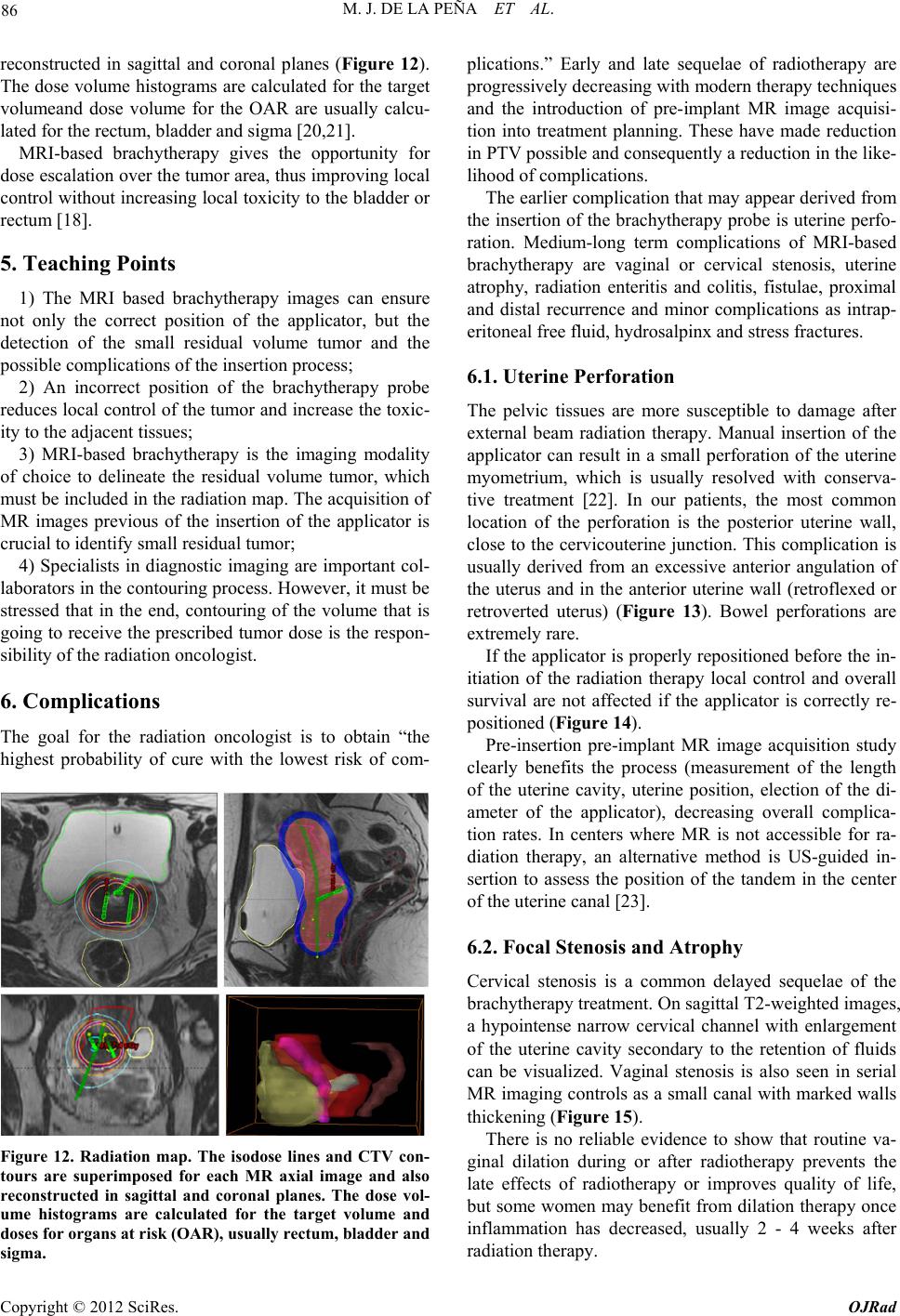 M. J. DE LA PEÑA ET AL. 86 reconstructed in sagittal and coronal planes (Figure 12). The dose volume h istograms are calculated for the target volumeand dose volume for the OAR are usually calcu- lated for the rectum, bladder and sigma [20,21]. MRI-based brachytherapy gives the opportunity for dose escalation over the tumor area, thus improving local control without increasing local toxicity to the bladder or rectum [18]. 5. Teaching Points 1) The MRI based brachytherapy images can ensure not only the correct position of the applicator, but the detection of the small residual volume tumor and the possible c omplications of the inse rtion process; 2) An incorrect position of the brachytherapy probe reduces local control of the tumor and increase the toxic- ity to the adjacen t tissues; 3) MRI-based brachytherapy is the imaging modality of choice to delineate the residual volume tumor, which must be included in the rad iation map. Th e acquisition of MR images previous of the insertion of the applicator is crucial to identify small residual tumor; 4) Specialists in diagnostic imaging are important col- laborators in the contouring process. However, it must be stressed that in the end, contouring of the volume that is going to receive the prescribed tumor dose is the respon- sibility of the radiation oncolo gist. 6. Complications The goal for the radiation oncologist is to obtain “the highest probability of cure with the lowest risk of com- Figure 12. Radiation map. The isodose lines and CTV con- tours are superimposed for each MR axial image and also reconstructed in sagittal and coronal planes. The dose vol- ume histograms are calculated for the target volume and doses for organs at risk (OAR), usually rectum, bladder and sigma. plications.” Early and late sequelae of radiotherapy are progressively decreasing with modern therapy techniques and the introduction of pre-implant MR image acquisi- tion into treatment planning. These have made reduction in PTV possible and consequ ently a reduction in the lik e- lihood of complications. The earlier complication that may appear derived from the insertion of the brachytherapy probe is uterine perfo- ration. Medium-long term complications of MRI-based brachytherapy are vaginal or cervical stenosis, uterine atrophy, radiation enteritis and colitis, fistulae, proximal and distal recurrence and minor complications as intrap- eritoneal free fluid, hydrosalpinx and stress fractures. 6.1. Uterine Perforation The pelvic tissues are more susceptible to damage after external beam radiation therapy. Manual insertion of the applicator can result in a small perforation of the uterine myometrium, which is usually resolved with conserva- tive treatment [22]. In our patients, the most common location of the perforation is the posterior uterine wall, close to the cervicouterine junction. This complication is usually derived from an excessive anterior angulation of the uterus and in the anterior uterine wall (retroflexed or retroverted uterus) (Figure 13). Bowel perforations are extremely rare. If the applicator is properly reposition ed before the in- itiation of the radiation therapy local control and overall survival are not affected if the applicator is correctly re- positioned (Figure 14). Pre-insertion pre-implant MR image acquisition study clearly benefits the process (measurement of the length of the uterine cavity, uterine position, election of the di- ameter of the applicator), decreasing overall complica- tion rates. In centers where MR is not accessible for ra- diation therapy, an alternative method is US-guided in- sertion to assess the position of the tandem in the center of the uterine canal [23]. 6.2. Focal Stenosis and Atrophy Cervical stenosis is a common delayed sequelae of the brachytherapy treatment. On sagittal T2-weighted images, a hypointense narrow cervical channel with enlargement of the uterine cavity secondary to the retention of fluids can be visualized. Vaginal stenosis is also seen in serial MR imaging controls as a small canal with marked walls thickening (Figure 15). There is no reliable evidence to show that routine va- ginal dilation during or after radiotherapy prevents the late effects of radiotherapy or improves quality of life, but some women may benefit from dilation therapy once inflammation has decreased, usually 2 - 4 weeks after radiation therapy. Copyright © 2012 SciRes. OJRad 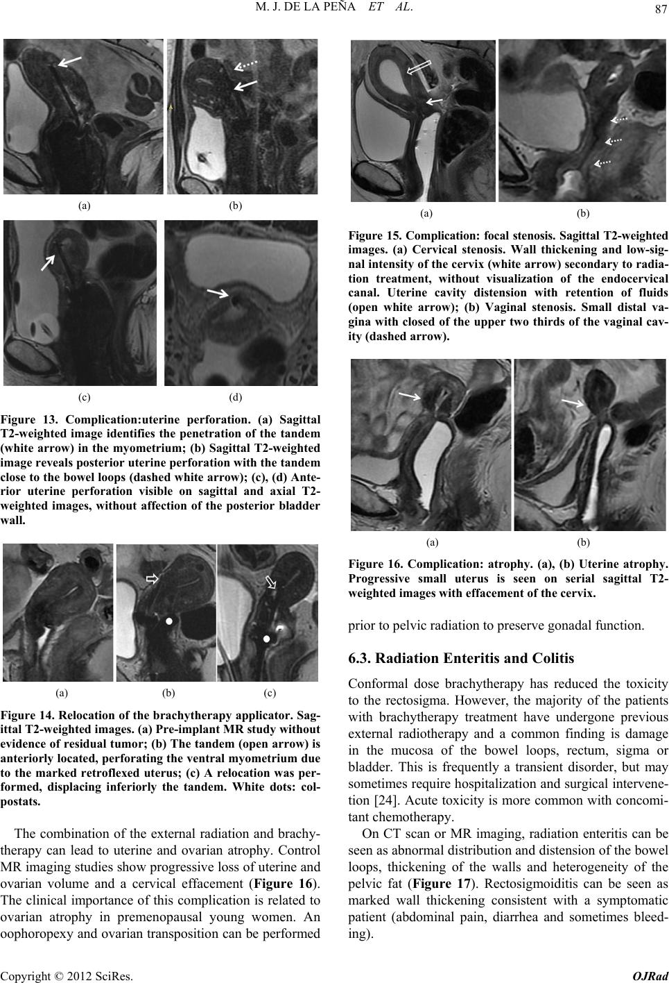 M. J. DE LA PEÑA ET AL. 87 (a) (b) (c) (d) Figure 13. Complication:uterine perforation. (a) Sagittal T2-weighted image identifies the penetration of the tandem (white arrow) in the myometrium; (b) Sagittal T2-weighted image reveals posterior uterine perforation with the tandem close to the bowel loops (dashed white arrow); (c), (d) Ante- rior uterine perforation visible on sagittal and axial T2- weighted images, without affection of the posterior bladder wall. (a) (b) (c) Figure 14. Relocation of the brachytherapy applicator. Sag- ittal T2-weighted images. (a) Pre-implant MR study without evidence of residual tumor; (b) The tandem (open arrow) is anteriorly located, perforating the ventral myometrium due to the marked retroflexed uterus; (c) A relocation was per- formed, displacing inferiorly the tandem. White dots: col- postats. The combination of the external radiation and brachy- therapy can lead to uterine and ovarian atrophy. Control MR imaging studies show progressive loss of uterine and ovarian volume and a cervical effacement (Figure 16). The clinical importance of this complication is related to ovarian atrophy in premenopausal young women. An oophoropex y and ovarian transposition can be performed (a) (b) Figure 15. Complication: focal stenosis. Sagittal T2-weighted images. (a) Cervical stenosis. Wall thickening and low-sig- nal intensity of the cervix (white arrow) secondary to radia- tion treatment, without visualization of the endocervical canal. Uterine cavity distension with retention of fluids (open white arrow); (b) Vaginal stenosis. Small distal va- gina with closed of the upper two thirds of the vaginal cav- ity (dashed arrow). (a) (b) Figure 16. Complication: atrophy. (a), (b) Uterine atrophy. Progressive small uterus is seen on serial sagittal T2- weighted images with effacement of the cervix. prior to pelvic radiation to preserve gonadal function. 6.3. Radiation Enteritis and Colitis Conformal dose brachytherapy has reduced the toxicity to the rectosigma. However, the majority of the patients with brachytherapy treatment have undergone previous external radiotherapy and a common finding is damage in the mucosa of the bowel loops, rectum, sigma or bladder. This is frequently a transient disorder, but may sometimes require hospitalization and surgical interven e- tion [24]. Acute toxicity is more common with concomi- tant chemotherapy. On CT scan or MR imaging, radiation enteritis can be seen as abnormal distribution and distension of the bowel loops, thickening of the walls and heterogeneity of the pelvic fat (Figure 17). Rectosigmoiditis can be seen as marked wall thickening consistent with a symptomatic patient (abdominal pain, diarrhea and sometimes bleed- ing). Copyright © 2012 SciRes. OJRad 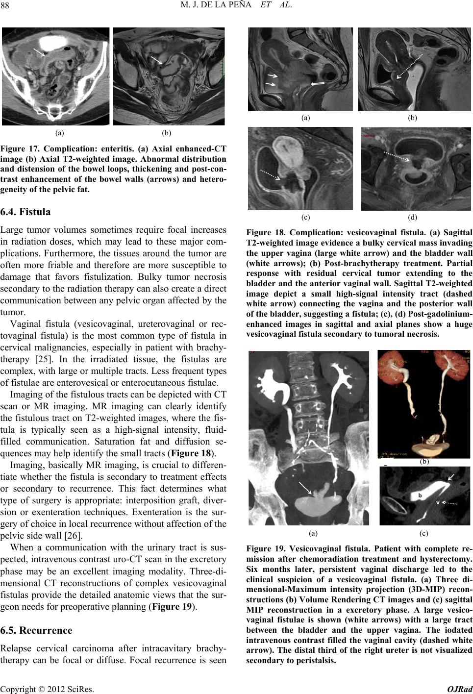 M. J. DE LA PEÑA ET AL. 88 (a) (b) Figure 17. Complication: enteritis. (a) Axial enhanced-CT image (b) Axial T2-weighted image. Abnormal distribution and distension of the bowel loops, thickening and post-con- trast enhancement of the bowel walls (arrows) and hetero- geneity of the pelvic fat. 6.4. Fistula Large tumor volumes sometimes require focal increases in radiation doses, which may lead to these major com- plications. Furthermore, the tissues around the tumor are often more friable and therefore are more susceptible to damage that favors fistulization. Bulky tumor necrosis secondary to the radiation therapy can also create a direct communication between any pelvic organ affected by the tumor. Vaginal fistula (vesicovaginal, ureterovaginal or rec- tovaginal fistula) is the most common type of fistula in cervical malignancies, especially in patient with brachy- therapy [25]. In the irradiated tissue, the fistulas are complex, with large or multiple tracts. Less frequent types of fistulae are enterovesical or enterocutaneous fistulae. Imaging of the fistulous tracts can be depicted with CT scan or MR imaging. MR imaging can clearly identify the fistulous tract on T2-weighted images, where the fis- tula is typically seen as a high-signal intensity, fluid- filled communication. Saturation fat and diffusion se- quences may help identify the small tracts (Figure 18). Imaging, basically MR imaging, is crucial to differen- tiate whether the fistula is secondary to treatment effects or secondary to recurrence. This fact determines what type of surgery is appropriate: interposition graft, diver- sion or exenteration techniques. Exenteration is the sur- gery of choice in local recurrence without affection of the pelvic side wall [26]. When a communication with the urinary tract is sus- pected, intravenous contrast uro-CT scan in the excretory phase may be an excellent imaging modality. Three-di- mensional CT reconstructions of complex vesicovaginal fistulas provide the detailed anatomic views that the sur- geon needs for preoperat ive planning (Figure 19). 6.5. Recurrence Relapse cervical carcinoma after intracavitary brachy- therapy can be focal or diffuse. Focal recurrence is seen (a) (b) (c) (d) Figure 18. Complication: vesicovaginal fistula. (a) Sagittal T2-weighted image evidence a bulky cervical mass invading the upper vagina (large white arrow) and the bladder wall (white arrows); (b) Post-brachytherapy treatment. Partial response with residual cervical tumor extending to the bladder and the anterior vaginal wall. Sagittal T2-weighted image depict a small high-signal intensity tract (dashed white arrow) connecting the vagina and the posterior wall of the bladder, suggesting a fistula; (c), (d) Post-gadolinium- enhanced images in sagittal and axial planes show a huge vesicovaginal fistula secondary to tumoral necrosis. (b) (a) (c) Figure 19. Vesicovaginal fistula. Patient with complete re- mission after chemoradiation treatment and hysterectomy. Six months later, persistent vaginal discharge led to the clinical suspicion of a vesicovaginal fistula. (a) Three di- mensional-Maximum intensity projection (3D-MIP) recon- structions (b) Volume Rendering CT images and (c) sagittal MIP reconstruction in a excretory phase. A large vesico- vaginal fistulae is shown (white arrows) with a large tract between the bladder and the upper vagina. The iodated intravenous contrast filled the vaginal cavity (dashed white arrow). The distal third of the right ureter is not visualized secondary to peristalsis. Copyright © 2012 SciRes. OJRad  M. J. DE LA PEÑA ET AL. 89 on T2-weighted images as hyperintense nodular ill-de- fined endoluminal mass and/or hyperintense lesions blur- ring the cervical stroma similar to the original tumor. Other radiological findings suggesting focal recurrence are marked restricted diffusion on spin echo diffusion weighted images and early enhanced in dynamic post- gadolinium sequences (Figure 20). The differential di- agnosis is nodular post-radiation treatment fibrosis (Fig- ure 21), appearing as hypointense or hyperintense nodu- lar lesions, with absent restricted diffusion and progress- sive gadolinium enhancement, although the definitive radiological diagnosis is no t always possible. A distal focal uterine recurrence sometimes occurs in the limits of the brachytherapy area. A hyperintensity mass in the uterine cavity can be id entified on sagittal or axial T2-weighted images with different degrees of myometrial invasion (Figure 22). Diffuse recurrence of cervical carcinoma can appear as multiple pelvic peritoneal implants, enlarged retroperito- neal enlarged lymph nodes or distant metastases. 6.6. Minor Complications Coexistent pathological pelvic minor complications [27] as intraperitoneal free fluid or small hydrosalpinx (Fig- ure 23) may often develop between the interval of the external beam radiotherapy and brachytherapy. Sacral insufficiency fractures are another possible (a) (b) (c) (d) Figure 20. Focal cervical recurrence. Vaginal distension with sterile gel. (a), (b) Focal ill-defined high-signal inten- sity mass (white arrow) on sagittal and axial T2-weighted images; (c) High-signal intensity on diffusion-weighted im- age and (d) increase nodular uptake of gadolinium contrast on enhanced sequence, suggesting cervical relapse. (a) (b) (c) (d) Figure 21. Post-brachytherapy treatment fibrosis. Vaginal distension with sterile gel. (a), (b) Cervical effacement (dashed white arrow) with diffuse low-signal intensity on sagittal and axial T2-weighted images; (c) Absence of ab- normal signal intensity on diffusion-weighted image; (d) Gadolinium-enhanced image do not show any uptake of contrast in cervical tissue. (a) (b) (c) (d) Figure 22. Distal uterine recurrence in a patient with a pre- vious complete regression of a cervical carcinoma after chemoradiation treatment. (a), (b) Sagittal and axial T2- weighted images reveal an intermediate-signal intensity mass in the uterine fundus (white arrows), invading the myometrium. Retention fluids are seen in the endometrial cavity (asterisk); (c) The compact mass is highly hyperin- tense on diffusion-weighted image and (d) enhances par- tially (white arrow) in post-gadolinium images. Copyright © 2012 SciRes. OJRad  M. J. DE LA PEÑA ET AL. 90 (a) (b) Figure 23. Hydrosalpinx. (a), (b) Small left hydrosalpinx (black arrow) is seen on coronal T2-weighted images as a high-signal intensity fluid filled tubular structure that arise s from the upper lateral margin of the uterus. (a) (b) Figure 24. Sacral insufficiency fractures. (a) Axial T1- weighted image shows symmetrical low-signal intensity in both sacral wings; (b) Axial T2-weighted image evidence bilateral abnormal high-signal intensity secondary to the medullary edema. Dashed ar rows: fractures lines. complication derived from the external radiation therapy that frequently appear at the time of the brachytherapy treatment. Hyperintensity areas on fat-suppressed T2- weighted images secondary to edema are clearly visual- ized in patients with back pain (Figure 24). 7. Conclusions Brachytherapy increases both local control and overall survival, especially in patients with advanced disease, indicating the critical role of brachytherapy in the treat- ment of malignant cervical tumors. Dose conformation with MRI-based brachytherapy improves local control and reduces the rate of complica- tions. In routine clinical practice, this procedure is feasi- ble and efficient for patients with locally advanced cer- vical cancer The radiologist must be familiarized with this increas- ingly-used therap y and its possible complications. REFERENCES [1] C. Balleyguier, E. Sala, T. Da Cunha, et al., “Staging of Uterine Cervical Cáncer with MRI: Guidelines of the Eu- ropean Society of Urogenital Radiology,” European Ra- diology, Vol. 21, No. 5, 2011, pp. 1102-1110. doi:10.1007/s00330-010-1998-x [2] C. Haie-Meder, B. Fevers, E. Fondrinier, M. Haugh, C. Lhomme and J. P. Guastalla, “SOR Guidelines for Con- comitant Chemoradiotherapy for Patients with Uterine Cervical Cancers: Evidence Update Bulletin 2004,” An- nals of Oncology, Vol. 16, No. 7, 2005, pp. 1110-1108. doi:10.1093/annonc/mdi220 [3] A. Sedlis, B. N. Bundy, M. Z. Rotman, S. S. Lentz, L. I. Muderspach and R. J. Zaino, “A Randomized Trial of Pelvic Radiation Therapy versus no Further Therapy in Selected Patients with Stage IB Carcinoma of the Cervix after Radical Hysterectomy and Pelvic Lymphadenec- tomy: A Gynecologic Oncology Group Study,” Gynecol- ogy Oncology, Vol. 73, No. 2, 1999, pp. 177-183. doi:10.1006/gyno.1999.5387 [4] P. G. Rose, “Concurrent Chemoradiation for Locally Advanced Carcinoma of the Cervix: Where Are We in 2006?” Annals of Oncology, Vol. 17, Suppl. 10, 2006, pp. x224-x229. doi:10.1093/annonc/mdl264 [5] S. Nag, H. Cardenes, S. Chang, et al., “Proposed Guide- lines for Image-Based Intracavitary Brachytherapy for Cervical Carcinoma: Report from Image-Guided Brachy- therapy Working Group,” International Journal of Radia- tion Oncology Biology Physics, Vol. 60, No. 4, 2004, pp. 1160-1172. doi:10.1016/j.ijrobp.2004.04.032 [6] H. Janaki, C. Zsolt, B. Péter, et al., “Application of MRI for Improved Local Control in Complex Radiotherapy of Cervical Cancer,” Archives of Oncology, Vol. 14, No. 3-4, 2006, pp. 95-100. doi:10.2298/AOO0604095H [7] C. Le Pechoux, Y. Akine, M. Sumi, et al., “High Dose Rate Brachytherapy for Carcinoma of the Uterine Cérvix: Comparison of Two Different Fractionation Regimens,” International Journal of Radiation Oncology Biology Physics, Vol. 31, No. 4, 1995, pp. 735-741. doi:10.1016/0360-3016(94)00573-7 [8] J. C. Lindergaard, J. Overgaard, S. M. Bentzen, et al., “Is There a Radiologic Basis for Improving the Treatment of Advanced Cervical Cancer?” Monographics National Cancer Institute, Vol. 21, 1996, pp. 105-112. [9] P. J. Eifel, “High Dose-Rate Brachytherapy for Carci- noma of the Cervix: High Tech or High Risk?” Interna- tional Journal Radiation Oncology Biology Physics, Vol. 24, No. 2, 1992, pp. 383-386. doi:10.1016/0360-3016(92)90696-F [10] F. D. Patel, S. C. Sharma, P. S. Negi, et al., “Low Dose Rate versus High Dose Rate Brachytherapy in the Treat- ment of Carcinoma of the Uterine Cervix: A Clinical Tri- al,” International Journal Radiation Oncology Biology Physics, Vol. 28, No. 2, 1994, pp. 335-341. doi:10.1016/0360-3016(94)90055-8 [11] C. Orton, “HDR: Forget Not ‘Time’ and ‘Distance’,” International Journal of Radiation Oncology Biology Physics, Vol. 20, No. 5, 1991, pp. 1131-1132. doi:10.1016/0360-3016(91)90215-P [12] R. Potter, T. H. Knocke, C. Fellner, et al., “Definitive Radiotherapy Based on HDR Brachytherapy with Iridium 192 in Uterine Cervix Carcinoma: Report on the Vienna University Hospital Findings (1993-1997) Compared to the Preceding Period in the Context of ICRU 38 Recom- Copyright © 2012 SciRes. OJRad  M. J. DE LA PEÑA ET AL. Copyright © 2012 SciRes. OJRad 91 mendations,” Cancer Radiotherapie, Vol. 4, 2000, pp. 159-172. [13] V. Viswanathan, J. Dimopoulus, C. Kirisits, et al., “Com- puted Tomography versus Magnetic Resonance Imag- ing-Based Contouring in Cervical Cancer Brachytherapy: Results of a Prospective Trial and Preliminary Guidelines for Standardized Contours,” International Journal Radia- tion Oncology Biology Physics, Vol. 68, No. 2, 2007, pp. 491-498. doi:10.1016/j.ijrobp.2006.12.021 [14] E. A. Barnes, G. Thomas, I. Ackerman, et al., “Prospec- tive Comparison of Clinical and Computed Tomography Assessment in Detecting Uterine Perforation with Intra- cavitary Brachytherapy for Carcinoma of the Cervix,” In- ternational of Journal Gynecological Cancer, Vol. 17, No. 4, 2007, pp. 821-826. doi:10.1111/j.1525-1438.2007.00888.x [15] A. N. Viswanathan, B. M. Buttin and A. M. Kennedy, “Oncodiagnosis Panel 2006: Ovarian, Cervical and En- dometrial Cancer,” Radiographics, Vol. 28, No. 1, 2008, pp. 289-307. [16] C. Kirisits, S. Lang, J. Dimopoulos, D. Berger, D. Georg and R. Pötter, “The Vienna Applicator for Combined In- tracavitary and Interstitial Brachytherapy of Cervical Cancer: Design, Application, Treatment Planning, and Dosimetric Results,” International Journal Radiation Oncology Biology Physics, Vol. 65, No. 2, 2006, pp. 624- 630. doi:10.1016/j.ijrobp.2006.01.036 [17] C. Haie-Meder, R. Pötter, E. Van Limburger, et al., “Gy- naecological (GYN) GEC-ESTRO Working Group. Re- commendations from Gynaecological (GYN) GEC-ES- TRO Working Group (I): Concepts and Terms in 3D Im- age Based 3D Treatment Planning in Cervix Cancer Bra- chytherapy with Emphasis on MRI Assessment of GTV and CTV,” Radiotherapy and Oncology, Vol. 74, No. 3, 2005, pp. 235-245. doi:10.1016/j.radonc.2004.12.015 [18] R. Pötter, C. Haie-Meder, E. Van Limbergen, et al., “Recommendations from Gynaecological (GYN) GEC ESTRO Working Group (II): Concepts and Terms in 3D Image-Based Treatment Planning in Cervix Cancer Bra- chytherapy-3D Dose Volume Parameters and Aspects of 3D Image-Based Anatomy, Radiation Physics, Radiobi- ology,” Radiotheraphy & Oncology, Vol. 78, No. 1, 2006, pp. 67-77. doi:10.1016/j.radonc.2005.11.014 [19] The Royal College of Radiologists, “Implementing Image Guided Brachytherapy for Cervix Cancer in the United Kingdom,” 2008. https://rcr.ac.uk/docs/oncology/pdf/BFCO(09)1_cervix.pdf [20] A. K. Berthelsena, J. Dobbsb, E. Kjell, et al., “What’s New in Target Volume Definition for Radiologists in ICRU Report 71? How Can the ICRU Volume Defini- tions Be Integrated in Clinical Practice?” Cancer Imaging, Vol. 7, No. 1, 2007, pp. 104-116. doi:10.1102/1470-7330.2007.0013 [21] J. C. Dimopoulos, G. Shard, D. Berger, et al., “System- atic Evaluation of MRI Findings in Different Stages of Treatment of Cervical Cancer: Potential of MRI on De- lineation of Target, Pathoanatomic Structures, and Organs at Risk,” International Journal Radiation Oncology Bi- ology Physics, Vol. 64, No. 5, 2006, pp. 1380-1388. doi:10.1016/j.ijrobp.2005.10.017 [22] W. Irvin, L. Rice, P. Taylor, W. Anderson and B. Schneider, “Uterine Perforation at the Time of Brachy- therapy for Carcinoma of the Cervix,” Gynecology On- cology, Vol. 90, No. 1, 2003, pp. 113-122. doi:10.1016/S0090-8258(03)00230-0 [23] C. J. McGinn, J. A. Stitt, D. A. Buchler and T. J. Kinsella, “Intraoperative Ultrasound Guidance during High Dose Rate Intracavitary Brachytherapy of the Uterine Cervix and Corpus,” Endocurie Hyperthermial Oncology, Vol. 8, 1992, pp. 101-104. [24] I. Ogino, T. Kitamura, N. Okamoto, et al., “Late Rectal Complications Following High Dose Rate Intracavitary Brachytherapy in Cancer of the Cervix,” International Journal Radiation Oncology Biology Physics, Vol. 31, No. 4, 1995, pp. 725-734. doi:10.1016/0360-3016(94)00547-8 [25] P. Narayanan, M. Nobbenhuis, K. M. Reynolds, et al., “Fistulas in Malignant Gynecologic Disease: Etiology, Imaging and Management,” Radi ographics, Vol. 29, 2009, pp. 1073-1083. doi:10.1148/rg.294085223 [26] J. S. Berek, C. Howe, L. D. Lagasse and N. F. Hacker, “Pelvic Exenteration for Recurrent Gynecologic Malig- nancy: Survival and Morbidity Analysis of the 45 Year Experience at UCLA,” Gynecology Oncology, Vol. 99, No. 1, 2005, pp. 153-159. doi:10.1016/j.ygyno.2005.05.034 [27] P. Beddy, R. Deepa Rangarajan and E. Salas, “Role of MRI in Intracavitary Brachytherapy for Cervical Carci- noma: What the Radiologist Needs to Know?” American Journal of Radiology, Vol. 196, 2011, pp. 341-347. Abbreviations GEC-ESTRO : Groupe Eur opéen de Curiethérapie; ABS: American Brachytherapy Society; GTV: Gross Target Volume; CTV: Clinical Target Volume; OAR: Organs at Risk; P TV: Planning Target Volume; MDCT: Multidetector CT; MIP: Maximum Intensity Projection; VR: Volume Rendered; U: Uterus; B: Bladder; R: Rectum; V: Vagina. |