Materials Sciences and Applications, 2012, 3, 596-599
http://dx.doi.org/10.4236/msa.2012.39085 Published Online September 2012 (http://www.SciRP.org/journal/msa)
Fatigue Crack Growth on Double Butt Weld with Toe
Crack of Pipelines Steel
Féthi Hadjoui1, Mustapha Benachour1, Mohamed Benguediab2
1Mechanical Engineering Department, Faculty of Technology, University of Tlemcen, Tlemcen, Algeria; 2Mechanical Engineering
Department, Faculty of Technology, University of Sidi Bel Abbes, Sidi Bel Abbes, Algeria.
Email: hadjoui_fethi@yahoo.fr
Received May 28th, 2012; revised June 29th, 2012; accepted July 30th, 2012
ABSTRACT
The welded structures have a broad applicability (car industry, aeronautical, marine, pipelines, etc.). The welding being
an assembled process, presents both advantages and disadvantages. A simple existing defect after welding can generate
a catastrophic fracture. This work studies the fatigue crack growth of double butt weld with toe crack. Two types of
pipeline material are studied with knowing API 5L grades X60 and X70 where tension form of loading is applied. In
order to predict the fatigue behavior of the welded structure, a constant amplitude loading is applied where the influence
of the stress ratio over the fatigue life is presented.
Keywords: Fatigue Crack Growth; Welding; Pipeline Material; Stress Ratio
1. Introduction
Today, most of the steel structures in engineering are
fabricated by welding. These welded structures are often
subjected to dynamic service loads. Welding present the
primary jointing method used in gas and oil pipelines.
Welded structures such as offshore structures, pressure
vessels and pipelines, are affected by fatigue loading. The
fatigue behavior of these welded structures is complicated
by many factors intrinsic to the nature of welded joints.
Many defects may be introduced in welded joints such as
lack of penetration at the weld root, undercutting at weld
toes, gas pores, etc. Near the defects zones stress conc-
entrations arise and favorite by the presence of residual
stress. Fatigue assessment procedures for welded structures
presented in reviewed work [1] have shown that the cu-
mulative damage under realistic stress affect the fatigue
limit. Frank [2] has shown that two types of cracking will
normally cause failure of a fillet welded joint. They are
root cracking and toe cracking.
Experimental fatigue tests of welded structures for the
national research institute of metal [3] have shown that
the fatigue failure origin change with the magnitude of
the stress range. Based on these tests, the fatigue crack
originated from the weld root when the stress range was
large and from the weld toe when the stress range was
small. Recently, Kainuma and Mori [4] have shown the
reason of change in origin of fatigue of weld structures in
our work. In welding operation, the presence of defects
in welded pipelines can be generated by damage during
the operating time. Most pipelines, used under stop and
start working conditions [5], are subjected to the low
cycle fatigue load [6].
The effect of butt weld geometry parameters (weld toe,
flank angle, plate thickness, initial crack geometry) on the
fatigue crack propagation life have been studied by Nguyen
and Wahab [7] by using Linear Elastic Fracture Mechanics
(LEFM). In other work, Nguyen and Wahab [8] devel-
oped a mathematical model to predict the overall effect of
the influencing weld geometry parameters such as (e.g.
weld toe radius, weld toe undercut, plate thickness, etc.)
and residual stresses on the fatigue strength and fatigue
life of butt-welded joints subjected to combined loading
(tensile and bending). It has been demonstrated that the
co-influence effect of weld toe-undercut with other butt-
weld geometry parameters is very significant. In particular,
fatigue crack growth behavior of welded joints depends on
the geometric configurations of the weld and plate thick-
ness [9].
Many studies [10,11] estimated the fatigue crack propa-
gation life of the weldment based on the fracture me-
chanics model and discussed the influence of the radius
at the weld toe. In the investigation conducted by Nykänen
et al. [12], the toe cracks initially perpendicular to the
plates, an initial crack length “ai” of 0.2 mm was assumed.
This length is typical when arc welding is used.
Moreover, several pipelines materials have been stud-
ied in the received or cutting in pipelines tubes with
the effects of several parameters. The effects of tough-
Copyright © 2012 SciRes. MSA
Fatigue Crack Growth on Double Butt Weld with Toe Crack of Pipelines Steel 597
ness on both the fatigue crack propagation rate (FCPR)
and the constant amplitude low cycle fatigue for low carbon
micro-alloyed pipeline steels (X60, X70, etc.) with various
microstructures and toughness are studied by Zhong et al.
[13]. The results indicate that the fatigue crack growth rate
and fatigue life were affected by increasing of tough-
ness. Under the same load, the fatigue life is greater for
X70 to X60. In Fazzini et al. (2007) work, pipeline mate-
rial X52 was studied. Fatigue tests were carried out to
characterize propagation of fatigue cracks in weld metal,
it was found that a large Paris exponent made the few
large amplitude cycles most contributing to crack propa-
gation. In research laboratory, many pipelines materials
are investigated. Fatigue X65 was studied by Duffet [14]
and Mokhdani [15]. The fatigue behavior is affected by
compressive residual stress induced by mechanical pre-
loading when the Paris’s law is applied. The crack pro-
pagation characteristics of X70 pipeline steel under cy-
clic loading are investigated by Mingxing et al. [16]. The
results indicate that the crack propagation is controlled
mainly the crack type stress intensity factor range K.
but the stress ratio has no effect on the crack propagation
rate in the synthetic high soil solution (pH = 9.3). Bena-
chour et al. [17] have presented the effect of stress ratio
on fatigue crack growth of double fillet weld. Other pa-
rameters have been investigated (initial crack length, angle
of weld and the range of the applied load). Results have
shown that the fatigue life is affected considerably by
these parameters.
The main objective of this work is to study the two
pipelines materials X60 and X70 under constant amplitude
loading for double butt weld with toe crack under the ef-
fects of loading parameters (stress ratio) and thickness of
welded specimen. The paper is organized as follow: Sec-
tion 2 presents studies material and introduces fatigue
crack growth simulation. Section 3 presents results and
discussion. Section 4 gives conclusions.
2. Fatigue Crack Growth Simulation
2.1. Materials and Specimen
Materials used in this study are the API 5L grades X60
and X70, subjected to numerical fatigue tests. The basic
mechanical properties for theses materials are given in
Table 1. The test specimen, double butt weld plate with
toe crack, is shown in Figure 1.
2.2. Fatigue Crack Growth Model
The estimation of the fatigue life of welded structures is
complicated by large variations in weld geometry, weld-
ing defects, residual stress, etc. The crack propagation is
the dominant part of the fatigue life. In order to predict
fatigue crack growth, several models were proposed by
different researchers. Among the proposed equations, the
Paris’s law [18] is commonly accepted and used in prac-
tice. The relationship between cyclic crack growth rate
and the range of cyclic stress intensity factor is charac-
terized by the materials parameters in Paris’s law as shown
in the following equation:
d
d
m
aCK
N (1)
where: ddaN is the fatigue crack growth rate, “C” and
m” are materials constants and “K” is the range of cyclic
stress intensity factor. The model elaborated by Paris is re-
commended in practice [19] for the calculations of fa-
tigue crack of welded joints made by steel. During ser-
vice of pipeline, the internal pressure varies, which re-
sults in a cyclic hoop stress. The variations of internal pres-
sures to the two limits Pmax and Pmin that generate fatigue
damage with an variable stress ratio equivalent to the
load stress R =
min/
max. The stress intensity factor in
loading mode has the following form:
π
K
a
  (2)
Equation (2) can be rewritten in the following form to
allow for the effect of weld geometry and residual stress
in loading mode, as follows:
0
π
I
keff
Ka

 M (3)
,
r
keffkak r
MMM




(4)
where
r: Maximum residual stress.
Mkeff: Effective stress intensity magnification factor pro-
duced by weld profile geometry and residual stress in speci-
fied loading mode.
Mka: Stress intensity magnification factor produced by
weld profile geometry in axial loading.
If the range of the stress intensity factor of a cracked
body is known, the fatigue crack propagation life Nr can
be calculated by integrating Equation (1) between the initial
Table 1. Mechanicals properties of the steels [13].
Pipeline Steel
0.2 (MPa)UTS
(MPa) A (%) E (GPa)
X60 454 519 29 206
X70 560 660 25 206
Figure 1. Double butt weld plate with toe crack.
Copyright © 2012 SciRes. MSA
Fatigue Crack Growth on Double Butt Weld with Toe Crack of Pipelines Steel
598
crack length “ai” and the final crack length at failure “af”.
In this study, the range of stress intensity factors is replaced
by the range of effective stress intensity factors (Keff) to
allow for the effect of the weld geometry and the residual
stresses. For the considered materials, the coefficient of
Paris’s law model C and m are presented in Table 2. The
number of cycles required to propagate a crack from an
initial crack size “a0” to a final crack “af” can be calcu-
lated by using the Equation (5) when numerical integra-
tion is applied.
0
d
f
a
fm
a
a
NCK

(5)
3. Results and Discussion
3.1. Fatigue Crack Growth in X60 Material
Double weld butt plate with toe crack was subject to a
tensile constant amplitude loading. Initial crack and final
crack are respectively 0.2 and 10 mm. The final crack
length fracture criterion is adopted for the limit of crack
growth.
The variation of crack length “a” VS number of cycle
N” is plotted in Figure 2 for fatigue crack growth of
pipeline material X60. In this figure, we show the effect
of stress ratio on fatigue life Nf. As the stress ratio in-
creases, the fatigue life increases. For the same maxmum
applied load (R = 0.1 and 0.2), the results are in good
agreement for the results of Srivastava and Garg [20]. A
shift of fatigue life curve for R = 0.3 is shown, this is due
to the amplitude loading effect when maximum applied
load are greater comparatively for R = 0.1 and 0.2. After
Table 2. Coefficients of Paris’s law model.
Pipeline Steel C m
X60 3.0 × 10¹⁰ 3.0
X70 1.7 × 10¹¹ 3.4
0
1
2
3
4
5
6
7
8
9
010000 200003000040000
N (number of Cycles)
C r a c k le ng th (mm)
R = 0.10
R = 0.20
R = 0.38
Figure 2. Effect of stress ratio on fatigue life for X60 pipe-
line material.
crack length 4 mm and in different stress ratio, the crack
growth with the same crack growth rate. The effect of
thickness specimen is presented in Figure 3. With same
final crack, we show a shift of fatigue curves. When thick-
ness increases, fatigue life deceases. This is due to the
effect of corrective of geometry and weld geometry func-
tion
(see Equations (2) and (3)).
3.2. Fatigue Crack Growth in X70 Material
In API 5L grade X70 material, the same specimen geome-
try is subjected to the same load (R = 0.1 and 0.2). We
have shown the same effect of increasing of stress ratio
(Fig ure 4) comparatively to the API 5L grade X60. Com-
parative study in fatigue life between the two materials is
plotted in Figure 5. In this figure, we have shown an in-
creasing of fatigue life in API 5L X70 pipeline materials.
This evolution is due to crack growth rate interpreted by
the slope m and parameter C in Paris’s law model. These
results prove that X70 pipeline materials present a good
resistance to the fatigue crack growth comparatively to
the X60 pipeline materials. The same conclusion is notic-
ed in experimental investigation of Zhong et al. [13].
4. Conclusion
In this paper simulation of fatigue crack growth on dou-
ble butt weld plate with toe crack of pipelines steel X60
0
2
4
6
8
10
010000 20000 30000 40000
N (number of Cycles)
Crack length (mm)
t = 12.0 mm
t = 9.6 mm
Figure 3. Thickness effect on fatigue crack growth life for
X60 pipeline material.
0
2
4
6
8
1
0
020000400006000080000 100000
N (nu m be r o f Cycl es )
C
rack len gt h
(
mm
)
R = 0.10
R = 0.20
Figure 4. Effect of stress ratio on fatigue life for X70 pipe-
line material.
Copyright © 2012 SciRes. MSA
Fatigue Crack Growth on Double Butt Weld with Toe Crack of Pipelines Steel
Copyright © 2012 SciRes. MSA
599
0
2
4
6
8
10
020000 4000060000 80000100000
N ( number of Cycles )
Crack length (m m)
API 5L X60
API 5L X70
[8] T. N. Nguyen and M. A. Wahab, “The Effect of Weld
Geometry and Residual Stresses on the Fatigue of Welded
Joints under Combined Loading,” Journal of Materials
Processing Technology, Vol. 77, No. 1-3, 1998, pp. 201-
208.
[9] J. A. M. Ferreira and C. M. Branco, “Influence of Weld
and Plate Geometry on the Fatigue Strength of Cruciform
Joints,” Theoretical and Applied Fracture Mechanics,
Vol. 9, No. 1, 1988, pp. 23-32.
doi:10.1016/0167-8442(88)90044-4
[10] S. J. Maddox, Met. Construct., Vol. 2, No. 8, 1970, pp.
327-335.
[11] J. A. M. Ferreira and C. M. Branco, “Influence of the
Radius of Curvature at the Weld Toe in the Fatigue
Strength of Fillet Welded Joints,” International Journal
of Fatigue, Vol. 11, No. 1, 1989, pp. 29-36.
doi:10.1016/0142-1123(89)90044-3
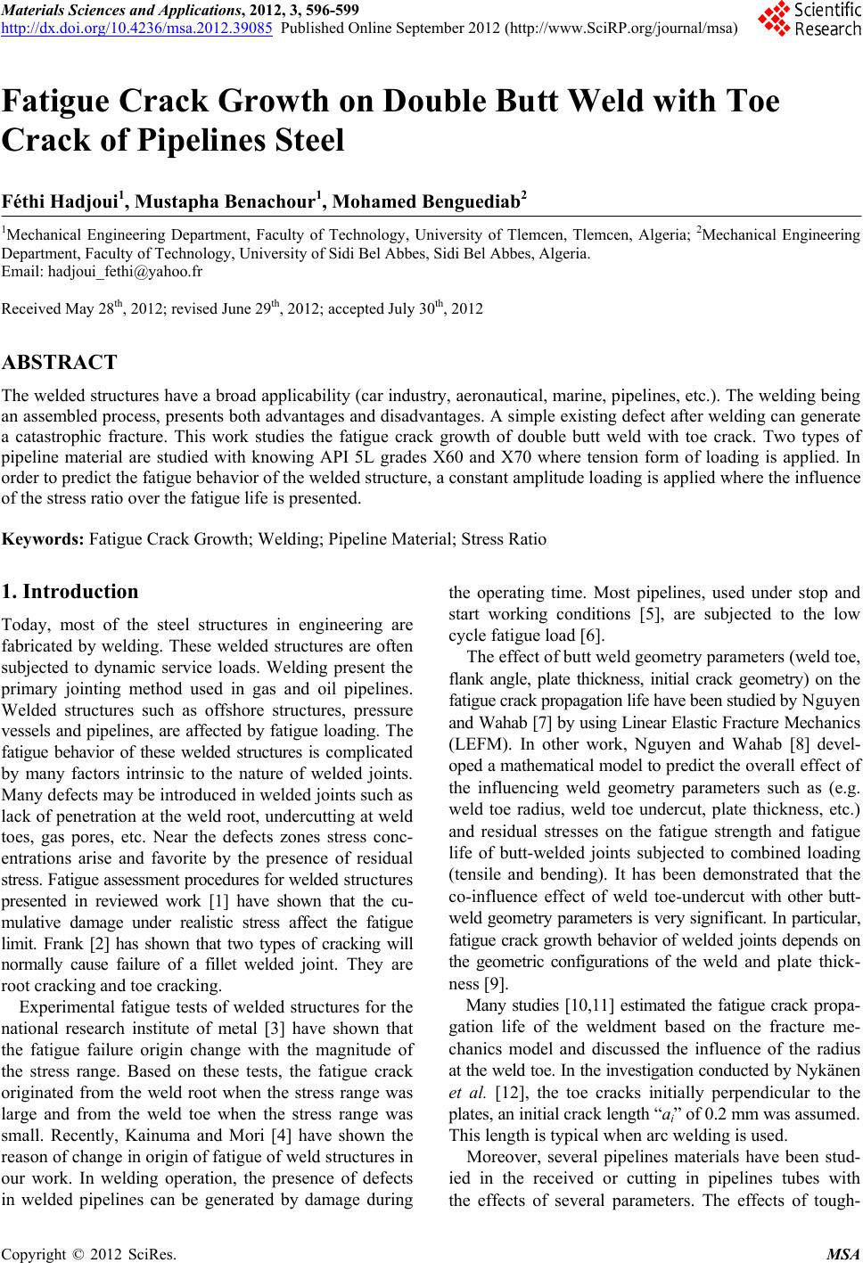
Figure 5. Comparison of fatigue life for API 5L X60 and
X70 pipeline steel at R = 0.2.
and X70 is investigated. Crack growth data show the influ-
ence of stress ratio. The fatigue life is affected by speci-
men thickness through the weld parameter geometry. Pipe-
line material steel API 5L grade X70 present good resis-
tance in fatigue crack growth comparatively to API 5L
grade X60. Resistance of this material (X70) is amelio-
rated high tensile stress.
[12] T. Nykänen, X. Li, T. Björk and G. Marquis, “A Para-
metric Fracture Mechanics Study of Welded Joints with
Toe Cracks and Lack of Penetration,” Engineering Frac-
ture Mechanics, Vol. 72, No. 10, 2005, pp. 1580-1609.
doi:10.1016/j.engfracmech.2004.11.004
[13] Y. Zhong, Y. Shan, F. Xia and K. Yang, “Effect of Tou-
ghness on Low Cycle Fatigue Behavior of Pipeline Steels,”
Materials Letters, Vol. 59, No. 14-15, 2005, pp. 1780-1784.
REFERENCES [14] G. Duffet, “Mechanisms and Criteria of Steel Delamina-
tion Ferrito-Perletic Micro-Alloyed Low-Carbon Produced
by Controlled Rolling,” Doctorate Thesis, University of
Franche-Conté, Paris, 1991.
[1] S. J. Maddox, “Fatigue Strength of Welded Structures,”
Cambridge University Press, Abington, 1991.
[2] K. H. Frank, Journal of Structural Division, Vol. 105,
1979, pp. 1727-1739. [15] C. Mokhdani, “Initiation and Propagation of the Fatigue
Cracks in a Steel for Tubes of Transport of Gas,” Doc-
torate Thesis, Ecole des Mines de Paris, Paris, 1995.
[3] NIRM, “Fatigue Data Sheet, No. 18: Data Sheets on Fa-
tigue Properties for Load-Carrying Cruciform Welded
Joints of SM50B Rolled Steel for Welded Structure,” Na-
tional Research Institute for Metals, 1980. [16] M
. X. Li, R. Wang, P. L. Li and M. X. Lu, Journal of
Chinese Society for Corrosion and Protection, Vol. 24,
2004, pp. 163-167.
[4] S. Kainuma and T. Mori, “A Study on Fatigue Crack
Initiation Point of Load-Carrying Fillet Welded Cruci-
form Joints,” International Journal of Fatigue, Vol. 30,
No. 9, 2008, pp. 1669-1677.
doi:10.1016/j.ijfatigue.2007.11.003
[17] M. Benachour, M. Benguediab, A. Hadjoui, F. Hadjoui
and N. Benachour, “Fatigue Crack Growth of a Double
Fillet Weld,Computational Materials Science, Vol. 44,
2008, No. 2, pp. 489-495.
doi:10.1016/j.commatsci.2008.04.015
[5] K. Kannan and J. P. Hirth, “Mixed Mode Fracture Tough-
ness and Low Cycle Fatigue Behavior in an HSLA-80
Steel,” Scripta Materialia, Vol. 39, No. 6, 1998, pp. 743-
748. doi:10.1016/S1359-6462(98)00185-7
[18] P. Paris and F. Erdogan, “A Critical Analysis of Crack
Propagation Laws,” Journal of Basic Engineering, Vol.
85, No. 4, 1963, pp. 528-534. doi:10.1115/1.3656900
[6] K. S. Chan, “Scaling Laws for Fatigue Crack,” Metallur-
gical and Materials Transactions A, Vol. 24, No. 11, 1993,
pp. 2473-2486.
[19] A. Hobbacher, “Fatigue Design of Welded Joints and
Components,” Abington Press, Abington, 1996.
[20] Y. P. Srivastava and S. B. L. Garg, “Influence of R on
Effective Stress Range Ratio and Crack Growth,” Engi-
neering Fracture Mechanics, Vol. 22, No. 6, 1985, pp.
915-926.
[7] T. N. Nguyen and M. A. Wahab, “A Theoretical Study of
the Effect of Weld Geometry Parameters on Fatigue
Crack Propagation Life,” Engineering Fracture Mechan-
ics, Vol. 51, No. 1, 1995, pp. 1-18.