Paper Menu >>
Journal Menu >>
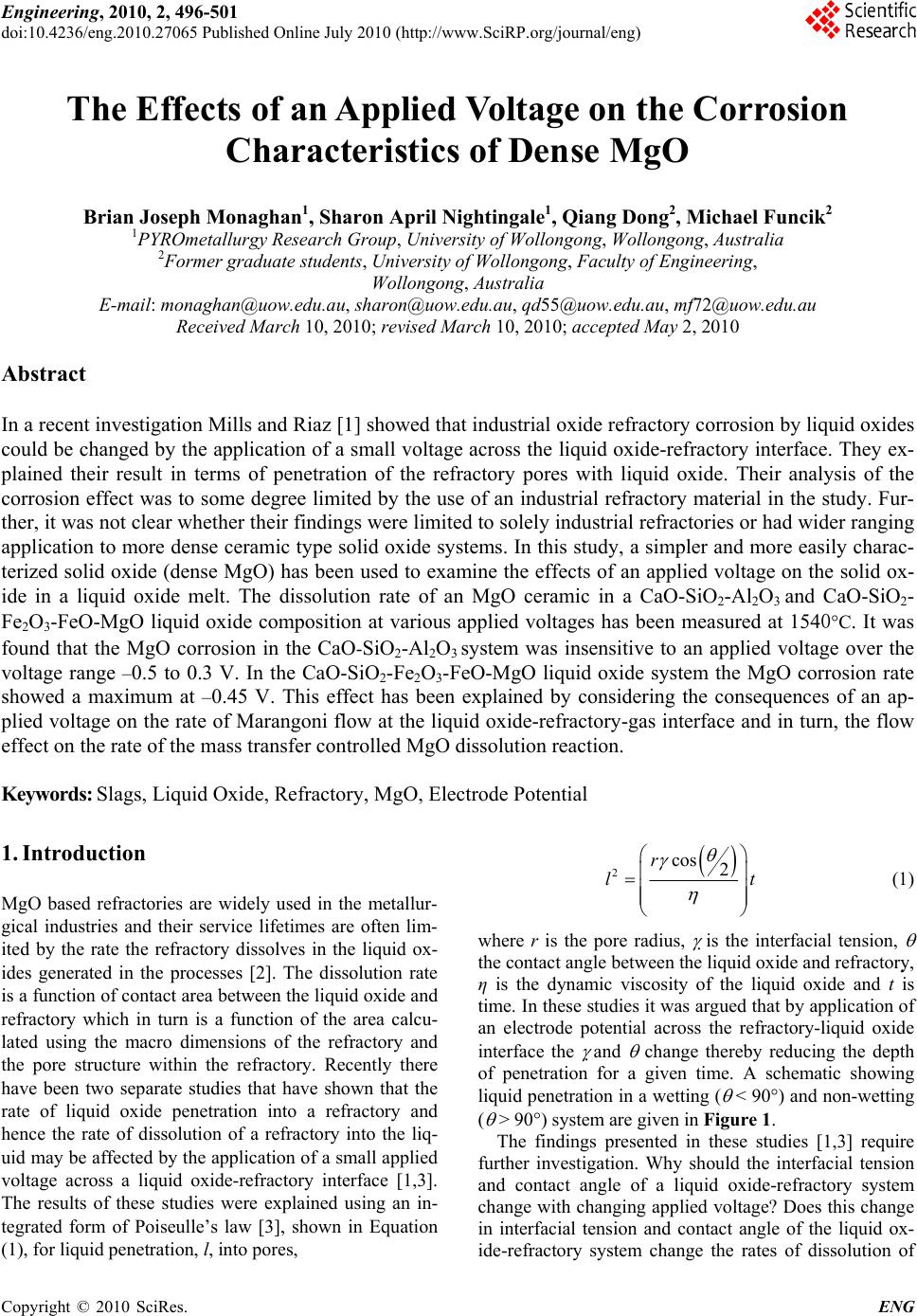 Engineering, 2010, 2, 496-501 doi:10.4236/eng.2010.27065 Published Online July 2010 (http://www.SciRP.org/journal/eng) Copyright © 2010 SciRes. ENG The Effects of an Applied Voltage on the Corrosion Characteristics of Dense MgO Brian Joseph Monaghan1, Sharon April Nightingale1, Qiang Dong2, Michael Funcik2 1PYROmetallurgy Research Group, University of Wollongong, Wollongong, Australia 2Former graduate students, University of Wollongong, Faculty of Engineering, Wollongong, Australia E-mail: monaghan@uow.edu.au, sharon@uow.edu.au, qd55@uow.edu.au, mf72@uow.edu.au Received March 10, 2010; revised March 10, 2010; accepted May 2, 2010 Abstract In a recent investigation Mills and Riaz [1] showed that industrial oxide refractory corrosion by liquid oxides could be changed by the application of a small voltage across the liquid oxide-refractory interface. They ex- plained their result in terms of penetration of the refractory pores with liquid oxide. Their analysis of the corrosion effect was to some degree limited by the use of an industrial refractory material in the study. Fur- ther, it was not clear whether their findings were limited to solely industrial refractories or had wider ranging application to more dense ceramic type solid oxide systems. In this study, a simpler and more easily charac- terized solid oxide (dense MgO) has been used to examine the effects of an applied voltage on the solid ox- ide in a liquid oxide melt. The dissolution rate of an MgO ceramic in a CaO-SiO2-Al2O3 and CaO-SiO2- Fe2O3-FeO-MgO liquid oxide composition at various applied voltages has been measured at 1540°C. It was found that the MgO corrosion in the CaO-SiO2-Al2O3 system was insensitive to an applied voltage over the voltage range –0.5 to 0.3 V. In the CaO-SiO2-Fe2O3-FeO-MgO liquid oxide system the MgO corrosion rate showed a maximum at –0.45 V. This effect has been explained by considering the consequences of an ap- plied voltage on the rate of Marangoni flow at the liquid oxide-refractory-gas interface and in turn, the flow effect on the rate of the mass transfer controlled MgO dissolution reaction. Keywords: Slags, Liquid Oxide, Refractory, MgO, Electrode Potential 1. Introduction MgO based refractories are widely used in the metallur- gical industries and their service lifetimes are often lim- ited by the rate the refractory dissolves in the liquid ox- ides generated in the processes [2]. The dissolution rate is a function of contact area between the liquid oxide and refractory which in turn is a function of the area calcu- lated using the macro dimensions of the refractory and the pore structure within the refractory. Recently there have been two separate studies that have shown that the rate of liquid oxide penetration into a refractory and hence the rate of dissolution of a refractory into the liq- uid may be affected by the application of a small applied voltage across a liquid oxide-refractory interface [1,3]. The results of these studies were explained using an in- tegrated form of Poiseulle’s law [3], shown in Equation (1), for liquid penetration, l, into pores, 2cos 2 r l t (1) where r is the pore radius, is the interfacial tension, the contact angle between the liquid oxide and refractory, η is the dynamic viscosity of the liquid oxide and t is time. In these studies it was argued that by application of an electrode potential across the refractory-liquid oxide interface the and change thereby reducing the depth of penetration for a given time. A schematic showing liquid penetration in a wetting ( < 90°) and non-wetting ( > 90°) system are given in Figure 1. The findings presented in these studies [1,3] require further investigation. Why should the interfacial tension and contact angle of a liquid oxide-refractory system change with changing applied voltage? Does this change in interfacial tension and contact angle of the liquid ox- ide-refractory system change the rates of dissolution of 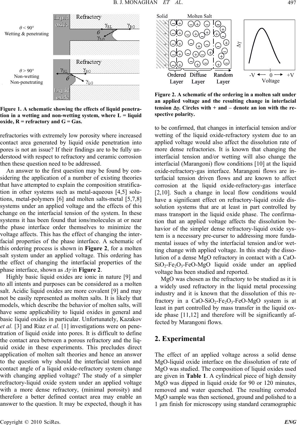 B. J. MONAGHAN ET AL.497 θ < 90° Wetting & penetrating θ > 90° Non-wetting Non- p enetratin g Figure 1. A sche matic showing the effects of liquid penetr a- tion in a wetting and non-wetting system, where L = liquid oxide, R = refractory and G = Gas. refractories with extremely low porosity where increased contact area generated by liquid oxide penetration into pores is not an issue? If their findings are to be fully un- derstood with respect to refractory and ceramic corrosion then these question need to be addressed. An answer to the first question may be found by con- sidering the application of a number of existing theories that have attempted to explain the composition stratifica- tion in other systems such as metal-aqueous [4,5] solu- tions, metal-polymers [6] and molten salts-metal [5,7,8] systems under an applied voltage and the effects of this change on the interfacial tension of the system. In these systems it has been found that ions/molecules at or near the phase interface order themselves to minimize the voltage affects. This has the effect of changing the inter- facial properties of the phase interface. A schematic of this ordering process is shown in Figure 2, for a molten salt system under an applied voltage. This ordering has the effect of changing the interfacial properties of the phase interface, shown as in Figure 2. Highly basic liquid oxides are ionic in nature [9] and to all intents and purposes can be considered as a molten salt. Acidic liquid oxides are more covalent [9] and may not be easily represented as molten salts. It is likely that models, which describe the behavior of molten salts, will have some applicability to liquid oxides in general and basic liquid oxides in particular. Unfortunately, Kazakov et al. [3] and Riaz et al. [1] investigations were on pene- tration of liquid oxide into pores. It is difficult to define the contact area between a porous refractory and the liq- uid oxide in these experiments. This precludes direct application of molten salt theories and hence an answer to the question why should the interfacial tension and contact angle of a liquid oxide-refractory system change with changing applied voltage? The study of a simpler refractory-liquid oxide system under an applied voltage with a more dense refractory, (minimal porosity) and therefore a better defined contact area may enable an answer to the question. It may be expected, though it has Solid – – – –+ + + + + + + + + + Molten Salt – – – – – – + + + + + + + – – – – – + + + ++ – –– – – Ordered Layer Diffuse Layer Random Layer Solid –– –– –– –– ++ ++ + + + + + ++ ++ ++ Molten Salt –– –– –– –– –– –– ++ ++ ++ ++ ++ ++ ++ –– –– –– –– –– ++ ++ ++ ++ ++ –– –– –– –– –– Ordered Layer Diffuse Layer Random Layer Voltage 0 -V +V Voltage 0 -V +V Voltage 0 -V +V Voltage 0 -V +V Solid –– –– –– –– ++ ++ + + + + + ++ ++ ++ Molten Salt –– –– –– –– –– –– ++ ++ ++ ++ ++ ++ ++ –– –– –– –– –– ++ ++ ++ ++ ++ –– –– –– –– –– Ordered Layer Diffuse Layer Random Layer Solid –– –– –– –– ++ ++ + + + + + ++ ++ ++ Molten Salt –– –– –– –– –– –– ++ ++ ++ ++ ++ ++ ++ –– –– –– –– –– ++ ++ ++ ++ ++ –– –– –– –– –– Ordered Layer Diffuse Layer Random Layer –– Ordered Layer Diffuse Layer Random Layer Voltage 0 -V +V Voltage 0 -V +V Voltage 0 -V +V Voltage 0 -V +V Figure 2. A sche matic of the orde ri ng in a molten salt under an applied voltage and the resulting change in interfacial tension . Circles with + and – denote an ion with the re- spective polarity. to be confirmed, that changes in interfacial tension and/or wetting of the liquid oxide-refractory system due to an applied voltage would also affect the dissolution rate of more dense refractories. It is known that changing the interfacial tension and/or wetting will also change the interfacial (Marangoni) flow conditions [10] at the liquid oxide-refractory-gas interface. Marangoni flows are in- terfacial tension driven flows and are known to affect corrosion at the liquid oxide-refractory-gas interface [2,10]. Such a change in local flow conditions would have a significant effect on refractory-liquid oxide dis- solution systems that are at least in part controlled by mass transport in the liquid oxide phase. The confirma- tion that an applied voltage affects the dissolution be- havior of the simpler dense refractory-liquid oxide sys- tem is a necessary pre-curser to addressing more funda- mental issues of why the interfacial tension and/or wet- ting change with applied voltage. In this study the disso- lution of a dense MgO refractory in contact with a CaO- SiO2-Fe2O3-FeO-MgO liquid oxide under an applied voltage has been studied and reported. MgO was chosen as the refractory to be studied as it is a widely used refractory in the liquid metal processing industry and it is known that the dissolution of this re- fractory in a CaO-SiO2-Fe2O3-FeO-MgO system is at least in part controlled by mass transfer in the liquid ox- ide phase [11,12] and therefore will be significantly af- fected by Marangoni flows. 2. Experimental The effect of an applied voltage across a solid dense MgO-liquid oxide interface on the dissolution of rate of MgO was studied. The composition of liquid oxides used are given in Tabl e 1. A cylindrical piece of high density MgO was dipped in liquid oxide for 90 or 120 minutes, removed and water quenched. The resulting corroded MgO sample was then sectioned, ground and polished to a 1 μm finish for microscopy using standard ceramographic Copyright © 2010 SciRes. ENG 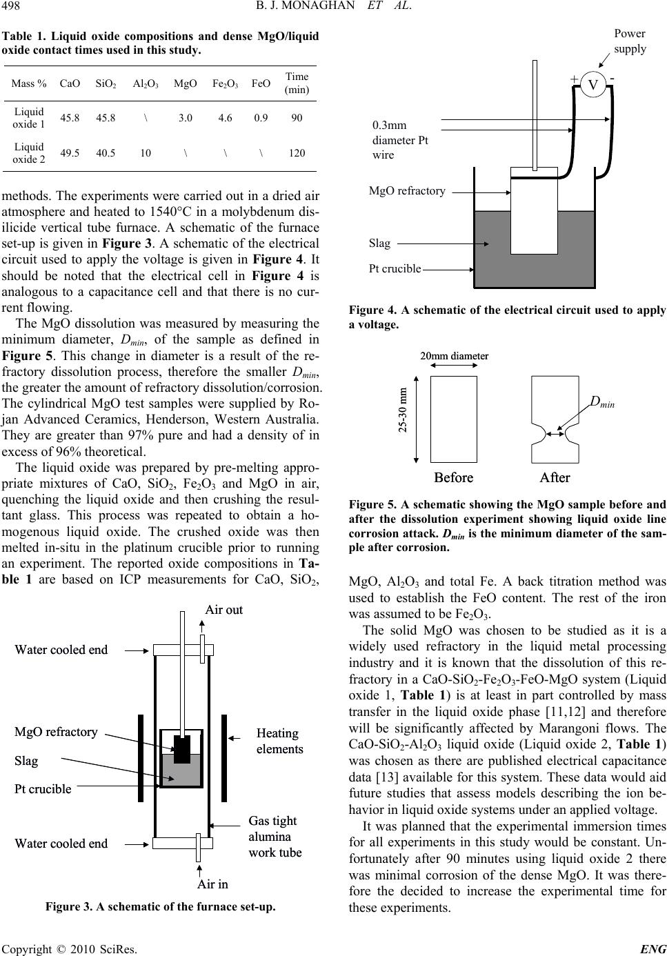 B. J. MONAGHAN ET AL. 498 Table 1. Liquid oxide compositions and dense MgO/liquid oxide contact times used in this study . Mass % CaO SiO2 Al2O3 MgO Fe2O3 FeO Time (min) Liquid oxide 1 45.8 45.8 \ 3.0 4.6 0.990 Liquid oxide 2 49.5 40.5 10 \ \ \ 120 methods. The experiments were carried out in a dried air atmosphere and heated to 1540°C in a molybdenum dis- ilicide vertical tube furnace. A schematic of the furnace set-up is given in Figure 3. A schematic of the electrical circuit used to apply the voltage is given in Figure 4. It should be noted that the electrical cell in Figure 4 is analogous to a capacitance cell and that there is no cur- rent flowing. The MgO dissolution was measured by measuring the minimum diameter, Dmin, of the sample as defined in Figure 5. This change in diameter is a result of the re- fractory dissolution process, therefore the smaller Dmin, the greater the amount of refractory dissolution/corrosion. The cylindrical MgO test samples were supplied by Ro- jan Advanced Ceramics, Henderson, Western Australia. They are greater than 97% pure and had a density of in excess of 96% theoretical. The liquid oxide was prepared by pre-melting appro- priate mixtures of CaO, SiO2, Fe2O3 and MgO in air, quenching the liquid oxide and then crushing the resul- tant glass. This process was repeated to obtain a ho- mogenous liquid oxide. The crushed oxide was then melted in-situ in the platinum crucible prior to running an experiment. The reported oxide compositions in Ta- ble 1 are based on ICP measurements for CaO, SiO2, Water cooled end MgO refractory Slag Heating elements Air in Air ou t Water cooled end Pt crucible Gas tight alumina work tube Water cooled end MgO refractory Slag Heating elements Air in Air ou t Water cooled end Pt crucible Gas tight alumina work tube Figure 3. A schematic of the furnace set-up. MgO refractory Slag Pt crucible 0.3mm diameter Pt wire Power supply V +- Figure 4. A schematic of the electrical circuit used to apply a voltage. Before After 20mm diameter 25-30 mm Dmin Before After 20mm diameter 25-30 mm Dmin D min Figure 5. A schematic showing the MgO sample before and after the dissolution experiment showing liquid oxide line corrosion attack. Dmin is the minimum diameter of the sam- ple after corrosion. MgO, Al2O3 and total Fe. A back titration method was used to establish the FeO content. The rest of the iron was assumed to be Fe2O3. The solid MgO was chosen to be studied as it is a widely used refractory in the liquid metal processing industry and it is known that the dissolution of this re- fractory in a CaO-SiO2-Fe2O3-FeO-MgO system (Liquid oxide 1, Table 1) is at least in part controlled by mass transfer in the liquid oxide phase [11,12] and therefore will be significantly affected by Marangoni flows. The CaO-SiO2-Al2O3 liquid oxide (Liquid oxide 2, Table 1) was chosen as there are published electrical capacitance data [13] available for this system. These data would aid future studies that assess models describing the ion be- havior in liquid oxide systems under an applied voltage. It was planned that the experimental immersion times for all experiments in this study would be constant. Un- fortunately after 90 minutes using liquid oxide 2 there was minimal corrosion of the dense MgO. It was there- fore the decided to increase the experimental time for these experiments. Copyright © 2010 SciRes. ENG 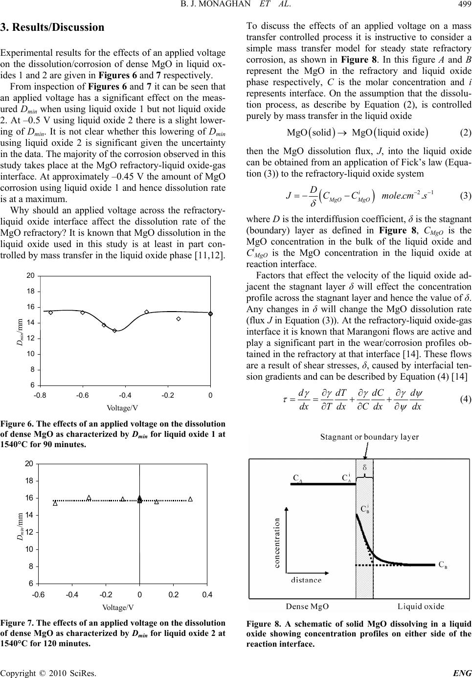 B. J. MONAGHAN ET AL.499 3. Results/Discussion Experimental results for the effects of an applied voltage on the dissolution/corrosion of dense MgO in liquid ox- ides 1 and 2 are given in Figures 6 and 7 respectively. From inspection of Figures 6 and 7 it can be seen that an applied voltage has a significant effect on the meas- ured Dmin when using liquid oxide 1 but not liquid oxide 2. At –0.5 V using liquid oxide 2 there is a slight lower- ing of Dmin. It is not clear whether this lowering of Dmin using liquid oxide 2 is significant given the uncertainty in the data. The majority of the corrosion observed in this study takes place at the MgO refractory-liquid oxide-gas interface. At approximately –0.45 V the amount of MgO corrosion using liquid oxide 1 and hence dissolution rate is at a maximum. Why should an applied voltage across the refractory- liquid oxide interface affect the dissolution rate of the MgO refractory? It is known that MgO dissolution in the liquid oxide used in this study is at least in part con- trolled by mass transfer in the liquid oxide phase [11,12]. 6 8 10 12 14 16 18 20 -0.8 -0.6 -0.4 -0.20 Volta g e/V Dmin/mm D min /mm Vo lta ge /V Figure 6. The effects of an applied voltage on the dissolution of dense MgO as characterized by Dmin for liquid oxide 1 at 1540°C for 90 minutes. 6 8 10 12 14 16 18 20 -0.6 -0.4 -0.200.20.4 Vol ta g e/V Dmin/mm Vo lta ge /V D min /mm Figure 7. The effects of an applied voltage on the dissolution of dense MgO as characterized by Dmin for liquid oxide 2 at 1540°C for 120 minutes. To discuss the effects of an applied voltage on a mass transfer controlled process it is instructive to consider a simple mass transfer model for steady state refractory corrosion, as shown in Figure 8. In this figure A and B represent the MgO in the refractory and liquid oxide phase respectively, C is the molar concentration and i represents interface. On the assumption that the dissolu- tion process, as describe by Equation (2), is controlled purely by mass transfer in the liquid oxide MgOsolid MgOliquid oxide (2) then the MgO dissolution flux, J, into the liquid oxide can be obtained from an application of Fick’s law (Equa- tion (3)) to the refractory-liquid oxide system 21 .. i MgO MgO D J CC molecms (3) where D is the interdiffusion coefficient, δ is the stagnant (boundary) layer as defined in Figure 8, CMgO is the MgO concentration in the bulk of the liquid oxide and Ci MgO is the MgO concentration in the liquid oxide at reaction interface. Factors that effect the velocity of the liquid oxide ad- jacent the stagnant layer δ will effect the concentration profile across the stagnant layer and hence the value of δ. Any changes in δ will change the MgO dissolution rate (flux J in Equation (3)). At the refractory-liquid oxide-gas interface it is known that Marangoni flows are active and play a significant part in the wear/corrosion profiles ob- tained in the refractory at that interface [14]. These flows are a result of shear stresses, δ, caused by interfacial ten- sion gradients and can be described by Equation (4) [14] ddTdCd dxTdxC dxdx (4) Figure 8. A schematic of solid MgO dissolving in a liquid oxide showing concentration profiles on either side of the reaction interface. Copyright © 2010 SciRes. ENG  B. J. MONAGHAN ET AL. 500 where x is distance, T is temperature, C is concentration and ψ voltage. Other symbols are as defined previously. For all other things being equal, a change in the voltage term in Equation (4), as a result the applied voltage to the liquid oxide-refractory system will be reflected by a change in the Marangoni flow velocity. This in turn will affect the MgO dissolution flux, as the thickness of the stagnant layer δ in Equation (3) will change. The MgO dissolution data as a function of applied voltage obtained in this study are consistent with, and therefore could be explained by such an argument. The argument that the applied voltage in the dense refractory-liquid oxide sys- tem studied in this investigation affects the interfacial phenomena, and hence the dissolution rate is consistent with Kazacov et al. [3] and Riaz et al. [1] explanation of the liquid oxide penetration observations of their porous refractory under an applied voltage. Essentially they ar- gued that applying a voltage to their porous refrac- tory-liquid oxide system changed the interfacial charac- teristics of the liquid oxide penetration. The argument for the voltage effect on MgO for dis- solution using liquid oxide 1 is based on the assumption that the MgO dissolution process is at least in part mass transfer controlled. Therefore providing MgO dissolution in a liquid oxide 2 is also at least in part mass transfer controlled a similar voltage effect should be observed. The results shown in Figure 7 do not bear this out. Why there is this discrepancy is not clear and requires further study. It may be that the expected voltage effect takes place outside the range tested in this study, or that the particular liquid oxide composition used and ions formed are not as susceptible to and applied voltage effect, or that the voltage effect is not as significant in liquid oxide 2 as liquid oxide 1 and therefore masked by the uncer- tainty in the results, or that the dissolution process of MgO in liquid oxide 2 is not controlled by mass transfer in the liquid oxide phase. It is unlikely that the dissolution process is not at least in part mass transfer controlled in the liquid oxide phase given previous work in this area [2,11,12], and more specifically [12] on the same solid liquid system, showed mass transfer control. From the results of using liquid oxide 1 in this study and the work of Kazacov et al. [3] and Riaz et al. [1] it can be seen that the corrosion of a refractory may be al- tered by applying a voltage across the refractory-liquid oxide interface. This phenomenon offers the potential to be able to control, among other things, refractory corro- sion in liquid metal production, a significant cost to many processes. At present, it is not possible to predict with any cer- tainty whether the applied voltage to the liquid ox- ide-refractory system will lessen or increase the dissolu- tion rate of the refractory. Nor is it known with any cer- tainty if any of the current models that have been devel- oped to describe the behavior of a solid-liquid interface when a voltage is applied across the interface [4-8] are applicable to liquid oxide-refractory systems. These models describe how the ions stratify at the solid-liquid interface under an applied voltage and that the stratifica- tion is a function of temperature, liquid oxide composi- tion (principally ion size) and liquid oxide capacitance. Our understanding of ion sizes in steelmaking liquid oxides is primarily limited to basic (depolymerised) liq- uid oxides [9]. The ions present in acid liquid oxides, for example liquid oxides rich in silica, are not well de- scribed [9]. The lack of knowledge of acid liquid oxides is not necessarily a major problem as most liquid oxides used in liquid steel processing are basic. Obtaining and utilizing liquid oxide capacitance data are key issues that must be addressed if a solution to the problems of direct application of the solid-liquid inter- face models to refractory dissolution that account for applied voltage effects are to be sought. There are very little capacitance data for liquid oxides [13,15,16]. This makes direct application of the solid-liquid interface models difficult. Also, if these data are to be used to con- firm which model is most appropriate for use in liquid oxide-refractory systems then an accurate description of the contact area between the liquid oxide and refractory is required. This contact area is more easily described for dense refractories. The confirmation that an applied vol- tage across a refractory-liquid oxide interface for dense MgO affects the MgO corrosion rate is an essential first step in developing and understanding of this important phenomenon. 4. Conclusions The effect of an applied voltage across the solid-liquid oxide interface on the dissolution rate of dense MgO refractory has been studied for two liquid oxide compo- sitions in the CaO-SiO2-Al2O3 and CaO-SiO2-Fe2O3- FeO-MgO liquid oxide systems respectively. It was found that the MgO corrosion in the CaO-SiO2-Al2O3 based liquid oxide proved insensitive to an applied volt- age over the voltage range –0.5 to 0.3 V. The corrosion rate of the dense MgO in the CaO-SiO2-Fe2O3-FeO-MgO proved to be effected by an applied voltage, showing a maximum corrosion rate at –0.45 V. This effect has been explained by considering the consequences of an applied voltage on the rate of Marangoni flow at the liquid ox- ide-refractory-gas interface and in turn, the flow effect on the rate of the mass transfer controlled MgO dissolu- tion reaction. The fact that the dissolution rate of a refractory can be altered by the application of a voltage across the re- fractory-liquid oxide interface offers a potential new tool to control refractory losses in liquid metal processing. Copyright © 2010 SciRes. ENG  B. J. MONAGHAN ET AL. Copyright © 2010 SciRes. ENG 501 5. References [1] S. Riaz, K. C. Mills and K. Bain, “Experimental Exami- nation of Liquid Oxide/Refractory Interface,” Ironmaking and Steelmaking, Vol. 29, No. 2, 2002, pp. 107-113. [2] W. E. Lee and S. Zhang, “Melt Corrosion of Oxide and Oxide-Carbon Refractories,” International Materials Re- views, Vol. 44, No. 3, 1999, pp. 77-104. [3] A. A. Kazakov, “Influence of the Electrical Potential on Converter Smelting,” Russian Metallurgy, Vol. 6, 1997, pp. 25-29. [4] R. R. Dogonadze and Y. A. Chizmadzhev, “Structure and Capacitance of the Metal-Fused Salt,” Interface Pro- ceedings Academy of Sciences USSR Physical Chemical Section, Vol. 157, No. 944, 1964, pp.778-781. [5] E. A. Ukshe, N. G. Bukun, D. I. Leikis and A. N. Frum- kin, “Investigation of the Electric Double Layer in Salt Melts,” Electrochimica Acta, Vol. 9, No. 4, 1964, pp. 431-439. [6] M. Vallet and B. Berge, “Electrowetting of Water and Aqueous Solutions on Poly(Ethylene Terephthalate) In- sulating Films,” Polymer, Vol. 37, No. 12, 1996, pp. 2465-2470. [7] F. D. Richardson, “Physical Chemistry of Melts in Metal- lurgy,” Academic Press, London, UK, 1974. [8] A. D. Graves, G. J. Hill and D. Inman, “Electrode Proc- esses in Molten Salts,” Advances in Electrochemistry and Electrochemical Engineering, Vol. 4, No. 117, 1966, pp. 159-159. [9] K. C. Mills, “Liquid Oxide Atlas,” 2nd Edition, Verlag Stalheisen GmBH, Dusseldorf, Germany, 1995. [10] N. Eustathopoulos, M. G. Nicholas and B. Drevet, “Wet- tability at High Temperatures,” 12th Edition, Pergamon Press, London, UK, 1999. [11] B. J. Monaghan, S. A. Nightingale, L. Chen and G. A. Brooks, “The Dissolution Behavior of Selected Oxides in CaO-SiO2-Al2O3 Liquid Oxides,” VII International Con- ferance on Molten Liquid oxides and Fluxes and Salts, SAIMM, Johannesburg, South Africa, 2004, pp. 585-594. [12] S. A. Nightingale, G. A. Brooks and B. J. Monaghan, “Degradation of MgO Refractory in CaO-SiO2-MgO- FeOx and CaO-SiO2-Al2O3-MgO-FeOx Liquid Oxides under Forced Convection,” Metallurgical and Materials Transactions B, Vol. 36B, No. 4, 2005, pp. 453-461. [13] M. Ashizuka and K. Oe, “Measurement of the Electrical Capacitance of the Double Layer at the Interface between CaO-SiO2, CaO-SiO2-Al2O3 and CaO-Al2O3 Oxide Melts,” Journal of the Japanese Institute of Metals, Vol. 39, No. 12, 1975, pp. 1243-1249. [14] K. Mukai, “Wetting and Marangoni Effect in Iron and Steelmaking Processes,” ISIJ International, Vol. 32, No. 1, 1992, pp. 19-25. [15] M. Ashizuka and K. Oe, “On the Capacitance of Platinum Electrode in Na2O-SiO2 Melts,” Journal of the Japanese Institute of Metals, Vol. 39, No. 4, 1975, pp. 388-393. [16] T. Emi, T. Sakuraya and K Sanbongi, “Electrochemical Studies of the Interfacial Phenomena at Metal/Molten Liquid Oxide Boundaries,” The 4th Japan–USSR Joint Symposium on the Physical Chemistry of Metallurgical Processes, The Iron and Steel Institute, Tokyo, Japan, 1973, pp. 72-86. |