Paper Menu >>
Journal Menu >>
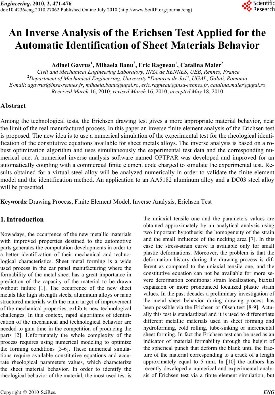 Engineering, 2010, 2, 471-476 doi:10.4236/eng.2010.27062 Published Online July 2010 (http://www.SciRP.org/journal/eng) Copyright © 2010 SciRes. ENG 471 An Inverse Analysis of the Erichsen Test Applied for the Automatic Identification of Sheet Materials Behavior Adinel Gavrus1, Mihaela Banu2, Eric Ragneau1, Catalina Maier2 1Civil and Mechanical Engineering Laboratory, INSA de RENNES, UEB, Rennes, France 2Department of Mechanical Engineering, University “Dunarea de Jos”, UGAL, Galati, Romania E-mail: agavrus@insa-rennes.fr, mihaela.banu@ugal.ro, eric.ragneau@insa-rennes.fr, catalina.maier@ugal.ro Received March 16, 2010; revised March 16, 2010; accepted May 18, 2010 Abstract Among the technological tests, the Erichsen drawing test gives a more appropriate material behavior, near the limit of the real manufactured process. In this paper an inverse finite element analysis of the Erichsen test is proposed. The new idea is to use a numerical simulation of the experimental test for the rheological identi- fication of the constitutive equations available for sheet metals alloys. The inverse analysis is based on a ro- bust optimization algorithm and uses simultaneously the experimental test data and the corresponding nu- merical one. A numerical inverse analysis software named OPTPAR was developed and improved for an automatically coupling with a commercial finite element code charged to simulate the experimental test. Re- sults obtained for a virtual steel alloy will be analyzed numerically in order to validate the finite element model and the identification method. An application to an AA5182 aluminum alloy and a DC03 steel alloy will be presented. Keywords: Drawing Process, Finite Element Model, Inverse Analysis, Erichsen Test 1. Introduction Nowadays, the occurrence of the new metallic materials with improved properties destined to the automotive parts generates the computation developments in order to a better identification of their mechanical and techno- logical characteristics. Sheet metal forming is a wide used process in the car panel manufacturing where the formability of the metal sheet has a great importance in prediction of the capacity of the material to be drawn without failure [1]. The occurrence of the new sheet metals like high strength steels, aluminum alloys or nano structured materials with the main target of improvement of the mechanical properties, exhibits new technological challenges. In this context, rapid algorithms of identifi- cation of the mechanical and technological behavior are needed to gain time in the competition of producing the parts [2]. Unfortunately the whole complexity of the process requires using numerical modeling to optimize the forming conditions [3-6]. These numerical simula- tions require available constitutive equations and accu- rate rheological parameters values, which characterize the sheet material behavior. In order to identify the rheological behavior of the material, the most used test is the uniaxial tensile one and the parameters values are obtained approximately by an analytical analysis using two important hypothesis: the homogeneity of the strain and the small influence of the necking area [7]. In this case the stress-strain curve is available only for small plastic deformations. Moreover, the problem is that the deformation history during the drawing process is dif- ferent as compared to the uniaxial tensile one, and the constitutive equation can not be available for more se- vere deformation conditions: strain localization, biaxial expansion or more pronounced localized plastic strain values. In the past decades a preliminary investigation of the metal sheet behavior during drawing process has been possible via the Erichsen or Olsen test [8-9]. Actu- ally this test is standardized and it is used to differentiate different metallic materials used in sheet forming and hydroforming, cold rolling, tube-sinking or incremental sheet forming. In fact the Erichsen test can be used as an indicator of material formability through the height of the spherical punch that deform the blank until the frac- ture of the material corresponding to a crack of a length approximately equal to 5 mm. In [10] the authors has recently developed a numerical and experimental analy- sis of Erichsen test via a finite element simulation, but  A. GAVRUS ET AL. 472 only the Erichsen index and the maximal values of the punch force are analyzed. Moreover, several studies based on the behavior analysis of the metallic plate or sheet subjected to a perpendicular impact with a hemi- spherical projectile [11], show the necessity to explore the material behavior in conditions close to a biaxial ex- pansion, generally developed during the Erichsen test. Consequently, the present paper proposes an application of the inverse analysis principle [12] to the constitutive parameters identification directly from the Erichsen ex- perimental device. The experimental measurements are represented by the recordings of the evolution of the drawing force with the depth of the sheet. The identifica- tion of the material coefficients is performed with a finite element simulation of the Erichsen test via an optimiza- tion procedure. The corresponding cost function is ex- pressed in terms of the experimental and numerical loads using a least squares formulation. In order to validate the proposed method, this paper neglects the sheet anisot- ropy (i.e. choice of materials without any anisotropy ef- fect) and the loads are supposed to be only quasi-static (i. e. no strain rate sensitivity). Numerical analysis and real results will be presented using the identification high board named OPTPAR (developed in the LGCGM labo- ratory), automatically coupled with a commercial finite element code (FORGE2 or MARC one [13]) charged to simulate the Erichsen test. 2. The Erichsen Experimental Test The design of the classical Erichsen test used in the Europe is defined by a hemispherical punch of steel with the diameter of 20 mm, an active die with the diameter of 27 mm, a blank holder with the diameter of 33 mm and a sheet with the diameter of 90 mm (see Figure 1(a) and Figure 1(b)). The ra dius of the d i e is 0.75 mm. The hemispherical punch is pressed into the sheet un til material fracture occurs, at which point the test is stopped immediately and the depth of the bulge recorded. This depth expressed in millimetres gives the Erichsen index (IE) and obviously giv es a measure of the ductility o f the sheet under biaxial stress conditions in the plane of the drawing. In a pure stretching forming the sheet is de- formed by the punch and is totally clamped. From a clas- sical point of view this test can be used only for com- parative purposes of sheet metals. Actually, measure- ment of the all axial punch force variation can be con- sidered as new potential experimental data. Until now it is not possible to develop a rigorous analytical theory of Erichsen test able to express the punch force in function of the test geometry and of the rheological parameters of the sheet material. It is the principal reason for each a numerical finite element model it is proposed to be used. (a) Punch (1) Blank Holder (2) Sheet ( 3 ) Die ( 5 ) (b) Figure 1. Experimental set-up of the Erichsen test: (a) 3D view (4, 6, 7–assembly components); (b) 2D asymmetric view. 3. Numerical Modeling and Analysis Starting from a finite element model, a blank, with a di- ameter of 90 mm and 3 mm of thickness, is meshed us- ing three nodes linear triangular elements (Figure 2). Figure 2. The numerical finite element model. Copyright © 2010 SciRes. ENG  A. GAVRUS ET AL.473 Re-meshing procedure is activated during the compu- tation process in order to eliminate numerical problems caused by degenerate elements which can occurs during the numerical simulation. The tools, spherical punch, die and blank holder, are considered to be rigid and the con- tact between the sheet and the blank holder or the hori- zontal part of the die is chosen to be a glued one. A Coulomb friction law with a friction coefficient of 0.1 is used between the sheet and the punch or the die active part. Considering an isotropic rheological law of the sheet material we can choose two different descriptions: (1) a Ludwick one and (2) a Voce one (see Figure 3): 00 n K (1) 00 1exp a n Kn (2) where 00 is the elastic yield stress, K is the material consistency and n is the hardening parameter. For a steel alloy we must choose na = 1. According to a virtual super plastic and ductile steel alloy, chosen in order to describe more pronounced plas- tic effects according to a stretching process, the values of the elastic and plastic material data are presented in Ta- ble 1. The numerical simulations have been realized using the FORGE2 commercial code (with an initial number of elements equal to 947) and with the MARC software (with an initial number of elements equal to 346). After 18 mm of the punch displacement the results of the de- formed mesh and of the cumulated plastic strain distribu- tion are pictured in Figure 4 and Figure 5. The similar results obtained with the both numerical codes confirm the availability o f the nu merical modeling. It is then possible to show that the necking phenomenon occurs at approximately 30 degree under the punch. 0 100 200 300 400 500 600 700 800 900 1000 00.1 0.2 0.3 0.4 0.5 0.6 0.7 0.8 0.91 Strain Equivalent Stress [MPa] Ludwick law Voce law Figure 3. Rheological laws used for the numerical simulation. Table 1. Material properties for a virtual steel sheet. E Elastic Data 210 GPa 0.3 0.1 Plastic Law 00 K n Ludwick324 MPa 401.76 MPa 0.514 Voce 324 MPa 281.46 MPa 5.14 Figure 4. Numerical finite element results obtained with FORGE2 (Mesh and cumulated plastic strain at t = 18 s). Figure 5. Numerical finite element results obtained with MARC (Mesh and cumulated plastic strain at t =18 s). Moreover, the obtained large values of the cumulated plastic strain (up to 150%) permits a deformation history analysis for more severe numerical conditions, very close to a real stretching or a drawing process of a super plastic alloy. Considering th e variation of the axial punch force, the results are plotted in Figure 6. These results show that similar curve shapes are obtained from the FORGE2 code and the MARC one. The small differences are caused by the numerical treatment of the contact phe- nomena, because different methods are used to adjust numerically the Coulomb law [13]. Concerning the influence of the material rheological law, we obtain a more pronounced softening with the Voce formulation of the stress-strain variation. The use of the extrapolation values for the stress from a classical Ludwick law can causes sev eral problems for the estima- Copyright © 2010 SciRes. ENG  A. GAVRUS ET AL. 474 0.00 10000.00 20000.00 30000.00 40000.00 50000.00 60000.00 70000.00 0.02.04.06.08.010.0 12.0 14.0 16.0 18.0 20.0 Time [ s ] Axial Pun ch Force [N] FORGE2_Luwdick MARC_Luwdick FORGE2_Voce Figure 6. Results of the axial punch force variation. tion of the process forces or for the computation of the deformation energies. 4. Validation of the Erichsen Test Simulation for an Aluminum Alloy In order to validate the finite element simulation of the Erichsen test, a deformation of an aluminum alloy AA5182 is analyzed. Experimentally, for 7.6 mm of the punch displacement, the thickness of the sheet in the necking area is approximately of 0.5 mm. The friction phenome- non and Coulomb parameter are considered to be a priori known (i.e. = 0.1) and in order to eliminate the ani- sotropy of aluminum alloys, a special thermal treatment has been used. So the rheological law is described only by a rigid plastic model (K = 0) where 00 is approxi- mately equal to 74 MPa. Particular problems caused by the sensitivity of the sheet deformation with respect to other constitutive parameters (as for example the hard- ening ones) are then avoided. Starting from a numerical finite element simulation via the FORGE2 software, the sheet geometry and the distribution of the plastic strain after 7.6 mm of the punch displacement is pictured in Figure 7. Figure 8 shows the fracture of the material obtained from the real experiment. It is important to note that nu- merically we obtain approximately the same final thick- ness of the sheet. Figure 7. The numerical finite element results obtained from FORGE2 (Mesh and cumulated plastic strain corre- sponding to 7.6 mm of the punch displacement). Figure 8. Image of the fracture obtained by experiment (Erichsen index e qual to 7. 8 mm). The cumulated plastic strain in the necking area is ap- proximately 60%, which corresponds to the analytical estimation of the logarithmic plastic strain obtained from the division between the initial and the final thickness. These results allow us to confirm that large plastic de- formations occur during the process and these ones can- not be obtained from a classical tensile test. Many ex- periments performed in laboratory LGCGM of INSA de RENNES, which compare the cumulated plastic strain values during a biaxial tensile test and a uniaxial tensile one, confirm this last assertion. Finally, complete content and organizational editing before formatting. Please take note of the following items when proofreading spelling and grammar. 5. Parameter Identification by Inverse Analysis Starting from the previous experimental and numerical analysis, accurate values of the constitutive parameters behaviour can be obtained using the inverse analysis principle. The experimental data can be represented by the recordings of the evolution of the punch force with the depth of the sheet (Figure 6). The identification of the material coefficients can be then performed with a finite element simulation of the Erichsen test via an op- timization procedure (OPTPAR, see Figure 9). Using the least squares formula the cost function is expressed in terms of the experimental forces and of the numerical ones by: exp exp 22 expexp exp 11 ,, NN cc ii i ii PF FFFF (3) where P is the parameter vector: , Nexp is the number of the experimental points, Fc is the finite ele- ment computed punch forces and the Fexp is the corre- sponding experimental data. ,PKn For a rheological identification problem, an appropri- ate physical domain of parameters variation must be in- troduced and a constrained optimization problem must be formulated as: exp () min max min( ,,) () / c PDP PF F DPP PPP (4) Copyright © 2010 SciRes. ENG 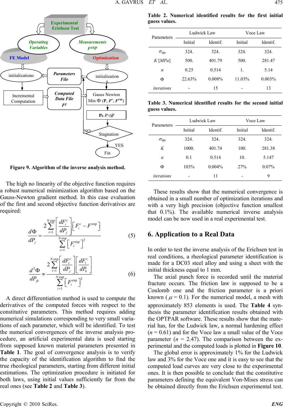 A. GAVRUS ET AL.475 N O YES Ex p erimental Erichsen Test FE Model initializations Incremental Computatio n Optimization initializatio n s P P+ P Stagnation P arameters F il e Com p ute d D ata Fil e F c Fin O p eratin g Variable s M easurements F exp Gauss Newton Min ( P, F c , F exp) Min (P, F c , F exp ) Figure 9. Algorithm of the inve rse analysis method. The high no linearity of the obj ective functio n requires a robust numerical minimization algorithm based on the Gauss-Newton gradient method. In this case evaluation of the first and second objective function derivatives are required: exp exp 1 exp 2 exp 1 2c N c i i ij N j i i dF FF dP d dP F (5) exp 21 exp 2 exp 1 2cc N ii ijk N jk i i dF dF dP dP d dP F (6) A direct differentiation method is used to compute the derivatives of the computed forces with respect to the constitutive parameters. This method requires adding numerical simulations corresp onding to very s mall varia- tions of each parameter, which will be iden tified. To test the numerical convergences of the inverse analysis pro- cedure, an artificial experimental data is used starting from supposed known material parameters presented in Table 1. The goal of convergence analysis is to verify the capacity of the identification algorithm to find the true rheological parameters, starting from different initial estimations. The optimization procedure is initiated for both laws, using initial values sufficiently far from the real ones (see Table 2 and Table 3). Table 2. Numerical identified results for the first initial guess values. Ludwick Law Voce Law Parameters Initial Identif. Initial Identif. 00 324. 324. 324. 324. K [MPa] 500. 401.79 500. 281.47 n 0.25 0.514 1. 5.14 22.63% 0.008% 11.03% 0.003% iterations - 15 - 13 Table 3. Numerical identified results for the second initial guess values. Ludwick Law Voce Law Parameters Initial Identif. Initial Identif. 00 324. 324. 324. 324. K 1000. 401.74 100. 281.38 n 0.1 0.514 10. 5.147 103% 0.004% 27% 0.07% iterations - 11 - 9 These results show that the numerical convergence is obtained in a small number of optimization iterations and with a very high precision (objective function smallest that 0.1%). The available numerical inverse analysis model can be now used in a real experimental test. 6. Application to a Real Data In order to test the inverse analysis of the Erichsen test in real conditions, a rheological parameter identification is made for a DC03 steel alloy and using a sheet with the initial thickness equ a l to 1 mm. The axial punch force is recorded until the material fracture occurs. The friction law is supposed to be a Coulomb one and the friction parameter is a priori known ( = 0.1). For the numerical model, a mesh with approximately 853 elements is used. The Table 4 syn- thesis the parameter identification results obtained with the OPTPAR software. These results show that the mate- rial has, for the Ludwick law, a normal hardening effect (n = 0.61) and for the Voce law a small value of the Voce parameter (n = 2.47). The comparison between the ex- perimental and the com puted loads is pl otted in Figure 10. The global error is approximately 1% for the Ludwick law and 3% for the Voce one and it is easy to see that the computed load curves are very close to the experimental ones. It is then possible to conclude that the constitutive parameters defining the equivalent Von-Mises stress can be obtained directly from the Erichsen experimental test. Copyright © 2010 SciRes. ENG  A. GAVRUS ET AL. Copyright © 2010 SciRes. ENG 476 8. Acknowledgements Table 4. Numerical parameter identification results for a real DC03 steel sheet. Ludwick Law Voce Law (na = 1) Parameters Initial Identified Initial Identified 00 150. 154.17 154.17 154.17 K [MPa] 500. 516.52 500. 484.33 n 0.25 0.61 10. 2.47 19.8% 1% 34.7% 2.7% iterations - 6 - 4 The present work was elaborated under the bilateral re- search agreement established between INSA de REN- NES-France and University “Dunarea de Jos” GALATI- Romania (UGAL), and financially supported by the re- search contracts CNCSIS 686/2007 and CEEX 24/2006 of the laboratory ITCM of UGAL. 9. References [1] D. Banabic, “Formability of Metallic Materials (Plastic Anisotropy, Formability Testing and Forming Limits),” Springer Verlag, Berlin, Germany, 2000. [2] R. Padmanabhan, M. C. Oliveir, J. L. Alves and L. F. Menezes, “Influence of Process Parameters on the Deep Drawing of Stainless Steel,” Finite Elements in Analysis and Design Archive, Vol. 43, No. 14, 2007, pp. 1062-1067. [3] J.-L. Batoz, H. Naceur and Y.-O. Guo, “Sheet Metal Stamp- ing Analysis and Process Design Based on the Inverse Ap- proach,” Proceeding of 10 th Esaform Conference on Mate- rials Forming, Zaragozza, Spain, 2007, pp. 1448-1453. [4] H. Naceur, A. Delamezier, J. L. Batoz, Y. O. Guo and C. K. Lenoir, “Some Improvements on the Optimum Process Design in Deep Drawing Using the Inverse Approach,” Journal of Materials Processing Techenology, Vol. 146, No. 2, 2004, pp. 250-262. [5] V. Paunoiu and D. Nicoara, “Simulation of Friction Phe- nomenon in Deep Drawing Process,” The Annals of Uni- versity “Dunărea de Jos” of Galaţi Fascicle VIII, Tribol- ogy, 2003, pp. 407-412. Figure 10. Comparison between experimental and com- puted axial punch forces corresponding to the previous identified rheologica l laws. [6] R. J. Comstock, K. Li and R. H. Wagoner, “Simulation of Axisymmetric Sheet Forming Tests,” Journal of Materi- als Processing Techenology, Vol. 117, No. 1, 2001, pp. 153-168. 7. Conclusions [7] W. G. Granzou, “Sheet Formability of Steel,” 10th Edi- tion, ASM International, Metals Handbook, Materials Park, Ohio, 1990. A robust optimization algorithm for the constitutive pa- rameters identification was developed from a numerical simulation of the Erichsen test. This inv erse method uses the commercial codes FORGE2 and MARC one starting only from the variation of the axial punch force. The inverse analyses, combined with numerical validations, robustness studies and validation through a real experi- ment, underlines the accuracy of the results obtained by proposed algorithm. The main feature of this identifica- tion methodology is linked to the possibility to take into account the all complexity of the test. The finite element model permits to simulate the biaxial stress conditions, together with a non-uniform distribution of the plastic strain and of the sheet thickness. It is then possible to obtain deformation cond itions close to those which occur during a real drawing or stretching process. In a future work, complementary experimental data, as for example the angular position of the necking radius together with he values of the sheet thickness variation, will be added. [8] B. Kaftanoglu and J. M. Alexander, “An Investigation of the Erichsen Test,” Journal of the Institute of Metals, Vol. 90, 1961, pp. 457- 470. [9] T. Y. Olsen, “Machines for Ductility Testing,” Proceeding of the American Society of Materials, Vol. 20 , 1920, pp. 398-403. [10] M. Akrout, M. B. Amar, C. Chaker and F. Dammak, “Numerical and Experimental Study of the Erichsen Test for Metal Stamping,” Advances in Production Engineer- ing & Management, Vol. 3, No. 2, 2008, pp. 81-92. [11] A. Gavrus, V. Grolleau and S. Diot, “Experimental and Numerical Analysis of an Impacted Thin Aluminum Plate,” Proceedings of Structures Under Shock and Im- pact VII, Montreal, 2002, pp. 477-486. [12] A. Gavrus, “Identification Des Parametres Rheologiques Par Analyse Inverse,” Phd Thesis, ENSMP, Paris, 1997. [13] MARC User’s Manual, Analysis Research Corporation, 1997. t |